manuals.online logo
Brands
  1. Home
  2. •
  3. Brands
  4. •
  5. NEC
  6. •
  7. Storage
  8. •
  9. NEC N8102-693 User manual

NEC N8102-693 User manual

CBZ-001279-693-01
大切に保管してください
Keep this manual carefully along with the product
この度は、本製品をお買い上げいただきまして誠にありがとうございます。
Congratulations for your purchase of this Memory Kit.
本増設メモリを本体装置へ取付ける際には本体装置に添付の使用上のご注意に記載されている冒頭の
内容をよく読んでご理解し、安全にご活用ください。また、増設にあたっては、最寄りの保守サービス
会社に依頼することをお勧めします。
The User's Guide is intended to allow you to install and use the Memory Kit.
N8102-693/694 correctly and safely Read this manual thoroughly before handling the Kit.
In addition, refer to this guide whenever you want to know how to use the Kit or some malfunction occurs.
Always keep this guide at hand so that you can see it when necessary.
For the server in which the Kit is installed, refer to the User’s Guide of the server.
Read “Notes on Use”carefully before handling the Kit.
警告
WARNING
安全上のご注意を無視する取り扱いを行うと、装置の故障、人体事故、火災・周囲の機器の損傷を
引き起こす原因となることがあります。
Indicates the presence of a hazard that may result in death or serious personal injury.
オプションの取り付け、取り外し時は電源プラグをコンセントから 電源プラグを抜く

抜き、外部装置と接続しているケーブルを外してください。 Unplug the power
故障や感電する恐れがあります。
cord!
When you install the option or delete it, unplug the power cord and 感電注意
extract
the
cable
that
has
connected
to
another one.
Otherwise, an electric shock or fire may be caused. Precaution against
electric shock
分解禁止
Prohibition of
本書に記載されている場合を除き、絶対に分解したり、修理・改造を
disassembly
行ったりしないでください。装置が正常に動作しなくなるばかりで 発火注意
なく、感電や火災の危険があります。
Indicates
that
Do not disassemble, repair, or modify the server. Otherwise,
an
improper
use
may
electric shock or fire may be caused.
cause
fire.
感電注意
Precaution against
electric shock

増設メモリボード取り扱いの手引き
N8102-693/694
DDR4-2400 REG Memory Kit User’s Guide
CBZ-001279-693-01
CBZ-001279-693-01

注意:本製品は、同一仕様のメモリをセットで使用する必要があります。本製品を購入して、すでに所有し
ているメモリと混在してしまった場合、メモリに貼ってあるメモリベンダのラベルを確認し、型番を
合わせてください。ラベルはベンダにより異なります、下記のラベル例を参照し型番を確認してくだ
さい。
INPORTANT:A pair of DIMMs of same specification must be installed in the server. If you have DIMMs of
various specifications, identify the model number by the label attached on the DIMM
ラベル例
Label sample
構成品
Composition article
項番

No.
品名
Name
数量
Number 備 考
Comment
N8102-
693 694
1 8GBRegisteredDIMM 2 − DDR4-2400
16GBRegisteredDIMM − 2 DDR4-2400
2 保証書 1 This warranty is valid
only in Japan.
3 増設メモリボード取り扱いの手引き
DDR4-2400 REG Memory Kit User’s Guide 1 本書
This book.
CBZ-001279-693-01
取り扱い上の注意事項
Notes On Use
本製品を箱から取り出した後は、次の注意事項を必ずお守りください。
Please be sure to protect the following notes after picking out this product from a box.
●ほこりの多い場所や大気中に硫黄の蒸気が発生する場所及び、水などの液体のかかるおそれのある
場所に置かないでください。
Do not use the server in the place where dust, water or liquid may pour.
●強い磁気を発生させるものの近くに置かないでください。
Do not use the server in the place where the strong electromagnetic waves generate.
●メモリの端子部分に触れないでください。
Do not touch any terminal pin of Additional Memory.
●N8102-693/694 増設メモリボード以外を搭載している場合は「メモリスペアリング機能」は使用
できません。
If you are equipped with a expansion memory board other than N8102-693/694, you can not use
"Memory Sparing feature".
●N8102-693/694 増設メモリボード以外の混在は出来ません。
It can not be used together N8102-693/694 expansion memory board other than.
第三者への譲渡
Transfer to Third Party
本製品を第三者へ譲渡(または売却)する場合には、本書を一緒にお渡しください。
Make sure to provide this manual and all the accessories along with the product to a third party.
CBZ-001279-693-01

製品の取り付け/取り外しについて
Installing or Uninstalling an Internal Optional Device
準備確認事項
Notes before carrying out the work
(1)危険防止及び故障防止のため作業を行なう際には、本体装置の電源スイッチを OFF にし、電源
プラグをコンセントから抜いてください。但し、ホットスワップ(活線挿抜)対象製品の取り付
け/取り外し時の電源スイッチの OFF および電源プラグのコンセントからの取り外しは除きます。
To avoid electric hazard and malfunction, be sure to turn off the Power switch of this product and
unplug the power cord from an outlet before carrying out the work. However, there is no need to do
this if the internal optional device is hot-swappable.
(2)本製品は静電気に弱い電子部品で構成されています。製品の取り付け/取り外しの際は、静電気
による製品の故障を防止するため静電気対策用リストストラップなどの装着により静電気を除去
してください。また、リストストラップを使用する場合は、接地された箇所に接続して使用して
ください。
This internal optional device consists of static-sensitive electronic components. To avoid failures
caused by static electricity when installing or uninstalling the internal optional device, wear an
anti-static wrist strap on your wrist and provide earthing before carrying out the work. And also
connect a wrist strap to earth ground when you wear a wrist strap.
(3)ケーブルの取り扱い
Handling of cables
LANケーブル等のケーブルを接続する場合も床面との摩擦によって静電気が帯電することが
あります。帯電した状態で入出機器に接続すると機器を破壊することがありますので接続する
前には除電キット等を使用して除電することを推奨します。
When connecting a cable (e.g., LAN cable), static electricity may also be charged due to friction
against the floor. Connecting a charged cable with an I/O device may cause damage to the
devices. It is recommended to discharge static electricity before connecting a cable by using
neutralization apparatus and so on.
注)静電気除電キットについて下記の静電気除電キットについては、お買い求めの販売店または保守
サービス会社にご相談ください。
品名:LANケーブル除電治具
型名:SG001(東京下田工業(株)製)
CBZ-001279-693-01

増設メモリの取り付け
Install the DDR4-2400 Memory Kit
1.準備確認事項
Preparation point to be checked
危険防止及び故障防止のため、作業を行なう際には本体装置の電源スイッチを OFF にし、電源プラグ
をコンセントから抜いてください。
To avoid danger and prevent malfunction, turn off the power of the server and unplug the power plug
from the outlet before performing the installation.
2.増設手順
Installation procedure
(1)メモリボード実装位置の確認
Check the position of the additional memory on the mother board.
①トップカバー/サイドカバーを取り外します。マザーボード上に増設用のコネクタがあります(下
図参照)。装置によっては、トップカバーの他にフレームの取り外しが必要な場合や、オプション
ボードの取り外しが必要な場合もあります。(本体装置のユーザーズガイド参照)
Remove the top or side cover and check the memory connector on the mother board.
In that case, it may be necessary to remove a frame in addition to the top cover, or it may be
necessary to remove an option board. (Please refer to USER’s GUIDE.)
マザーボード
Mother Board
CPU1_DIMM1
CPU1_DIMM5
CPU1_DIMM2
CPU1_DIMM6
CPU1_DIMM8
CPU1_DIMM4
CPU1_DIMM7
CPU1_DIMM3
CPU2_DIMM6
CPU2_DIMM2
CPU2_DIMM5
CPU2_DIMM1
CPU2_DIMM3
CPU2_DIMM7
CPU2_DIMM4
CPU2_DIMM8
CBZ-001279-693-01

(2)メモリボードの実装手順
Install the DDR4-2400 Memory Kit
①メモリボードには誤挿入防止用の切り欠きがありますので、コネクタの極性と切り欠きを同一
方向に合わせます。コネクタに対してメモリボードを垂直に立てて挿入するとレバーが自動的に
閉じます。同様の手順で残りのメモリボードを実装します。
The memory card has cutouts to prevent incorrect insertion. Please orient the card so that the
connector polarity and card cutouts match.
Insert the card vertically on the connector. Press the levers at each end of the connector so that
they fasten the half-circle shaped cutouts on each edge of the card.
INPORTANT
切り欠き
Key Slot 誤挿入防止キー
Key
メモリボードは左右非対象の形状ですので、メモリボードとメモリソケット
の凹凸部分を確認し、正しく実装してください。メモリボードが正しく固
定されないと本体の故障の原因になりますので、特に注意してください。
Since a memory card has unsymmetrical shape, please check the
concavo-convex part of a memory card and a connector, and mount it
correctly.
Please exercise caution. Improperly fastened memory card can cause
malfunctioning of the main unit.
CBZ-001279-693-01
(3)メモリボードの増設順序
The extension order of memories
●メモリボードは次の順序で増設します。(下図参照)
A memory card is added by the next order.
●1CPU構成時と2CPU構成時でメモリの増設順序が違います。
When one CPU is composition and two CPU are composed, the order of increasing the memory
is different.
●1CPU構成時は下図の1CPU構成に記載の順序で増設してください。
The 1 CPU configuration is added by an order of mentioning to the 1 CPU configuration in the
below figure.
●2CPU構成時は下図の2CPU構成に記載の順序で増設してください。
The 2 CPU configuration is added by an order of mentioning to the 2 CPU configuration in the
below figure.
●メモリボードの増設は、容量の大きいもの(16GB→8GB)から順に増設して
ください。
Something by which addition of a memory board has a large capacity, it's added in turn from
(16GB -> 8GB).
INPORTANT
It can not be used together N8102-693/694 memory expansion board
other than.
If you have not implemented the CPU2, you can not use
CPU2_
DIMM1
-
8
.
1CPU
構成
1CPU configuration
2CPU
構成
2CPU configuration
4 枚め/4
th
1 枚め/1
st

2 枚め/
2
nd

4 枚め/4
th

2 枚め/2
nd

4 枚め/4
th

3 枚め/
3
rd

1
枚
め
/
1
st

3 枚め/3
rd

8 枚め/ 8
th
4 枚め/
4
th
8 枚め/ 8
th

1 枚め/
1
st

5 枚め/
5
th

1 枚め/
1
st

5 枚め/
5
th

6 枚め/
6
th

2 枚め/2
nd

6
枚
め
/
6
th

2 枚め/
2
nd

7 枚め/
7
th

3 枚め/
3
rd

7 枚め/
7
th

3 枚め/
3
rd

CBZ-001279-693-01

3.増設後の確認
Operation Check after Installation
(1)本メモリボードを増設後、本体装置の画面が表示されない場合は、基本で実装されているメモリ
も含めて、再度すべてのメモリが正しく実装されているか確認してください。
After adding this memory card, if nothing is displayed on the main unit screen, please reconfirm
that all memories including pre-installed ones are properly mounted.
(2)POST の画面でエラーメッセージが表示されていないことを確認してください。
Power on the server and verify that POST displays no error messages.
(3)本体装置の「SETUP」を立ち上げ、「Advanced」−「MemoryConfiguration」−「MemoryInformation」
を選択し、増設したメモリの DIMM ステータス表示が「数値」になっていることを確認してください。
Run the BIOS SETUP utility and select [Advanced] →[Memory Configuration] −「Memory
Information」to verify that the installed DIMM shows the status “Number”.
(4)増設したメモリが認識されない場合は、本体装置の「SETUP」を立ち上げ、「Advanced」―
「MemoryConfiguration」−「MemoryRetest」で「Yes」を選択して、メモリのエラー情報を
クリアしてください。
「SETUP」の立ち上げ、選択方法等は、本体装置の EXPRESSBUILDER に格納されているユーザーズガ
イドを参照してください。
Select “Yes”for 「Memory Retest」on the 「Advanced」−「Memory Configuration」menu.
4.メモリ機能の利用
Using the Memory RAS Features
(1)本製品は、メモリ RAS 機能として「メモリスペアリング機能」を持っています。メモリスペア
リング機能は、各 CPU のメモリコントローラ配下にあるメモリチャンネルの 1 つを予備(スペア)と
して待機させることにより、運用しているメモリチャネル配下の DIMM で訂正可能なエラーが発生
した場合、待機させている DIMM に自動的に運用を切り替え、処理を継続させる機能です。
The server has RAS feature including "Memory sparing feature".
The memory sparing feature by making one of the memory channels which the memory controller
subordinate of each CPU has stand by as a reserve (spare), When the error which can be
corrected by DIMM of the memory channel subordinate who is applying occurs, it is the function to
change employment to DIMM made to stand by automatically, and to make processing continue.
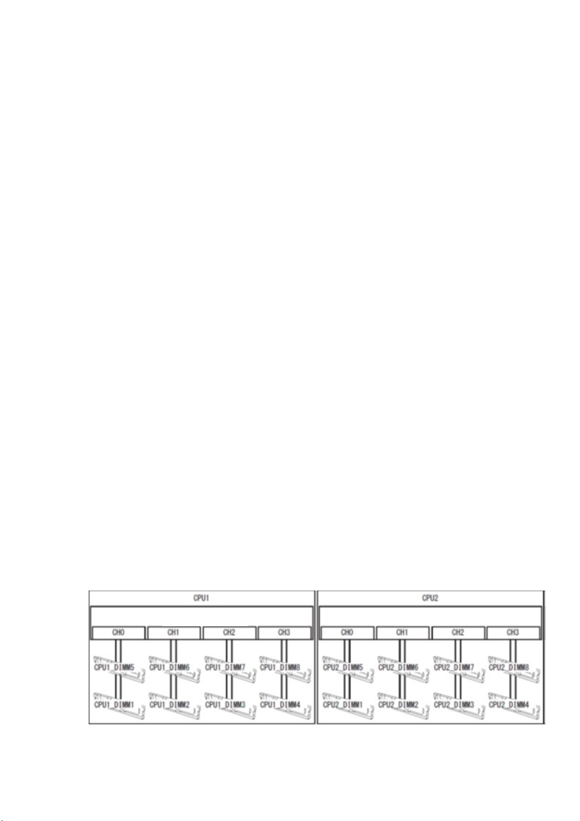
(2)本体装置のマザーボードは、メモリを制御するための「メモリチャンネル」が 4 系統に分かれてい
ます。
The memory area on the motherboard of the server is divided into four memory channels as shown
in the figure below.
メモリコントローラ

Memory Controller
メモリコントローラ

Memory Controller
CBZ-001279-693-01
(3)メモリスペアリング機能
Memory Sparing
メモリスペアリング機能は、各 CPU のメモリコントローラ配下にあるメモリチャネルの 1 つを予備
(スペア)として待機させることにより、運用しているメモリチャネルは以下の DIMM で訂正可能な
エラーが発生した場合、待機させている DIMM に自動的に運用を切り替え、処理を継続させる機能です。
Memory Sparing feature puts a memory channel 2 of a memory controller in each CPU into standby
status as spare devices. If a correctable error occurs in a DIMM in the running memory controller, the
feature automatically changes the running DIMM from the failed one to a DIMM in the standby state
to continue the processing.
Check
メモリスペアリングをサポートする構成と、その際のシステム論理メモリの容量は次の表を参照
してください。
Refer to the figure below about the configuration of the memory supports Sparing feature and
the system logical capacity.
CPU 個数
Number of
CPUs
メモリ枚数
Memory
搭載メモリ容量
Memory Capacity
N8102-
693(16GBx2)

694(32GBx2)
1
2 24GB 48GB
4 48GB 96GB
6 72GB 144GB
8 96GB 192GB
2
4 48GB 96GB
6 72GB 144GB
8 96GB 192GB
10 120GB 240GB
12 144GB 288GB
14 168GB 336GB
16 192GB 384GB
オペレーティングシステムからは、実際に搭載したサイズより少なく認識
されます(DIMM の搭載数と 1 枚あたりの容量によって変わります)。
The operating system recognizes the DIMMs as those with capacities
less than the actual physical capacities. (The recognized capacities
DIMM.)
●
メモリスペアリング機能を使うときは、N8102-693/694 増設メモリ
ボード(同一 DIMM2 枚セット)を搭載してください。
To use Memory Sparing feature, install N8102-693/694 additional
memory board (two DIMMs of same model).
●システム内に搭載するメモリは同一型番のメモリを搭載して
ください。
DIMMs installed in the system must be of the same model number.
CBZ-001279-693-01

待機系
Standby
CPU2DIMM2

スペアセット
Spare set
#
4
CPU2DIMM6

CPU2DIMM7

CPU2DIMM3

スペアセット
Spare set
#
6
CPU2DIMM8

CPU2DIMM4

スペアセット
Spare set
#
8
運用系
Running
CH0
CH1
CH2
CH3
メモリコントローラ
Memorycontroller

CPU2
CPU2DIMM1

スペアセット
Spare set
#
2
CPU2

DIMM5

例:2CPU
Example:2CPU configuration
待機系
Standby
CPU1DIMM7

CPU1DIMM3

スペアセット
Spare set
#
5
CPU1DIMM8

CPU1DIMM4

スペアセット
Spare set
#
7
運用系
Running
CH0 CH1 CH2 CH3
メモリコントローラ
Memorycontroller

CPU1
CPU1DIMM2

スペアセット
Spare set
#
3
CPU1DIMM6

CPU1DIMM1

スペアセット
Spare set
#
1
CPU1DIMM5

CBZ-001279-693-01
この機能を利用するための条件は次のとおりです。
The memory mirroring feature can be used under the following conditions.
●スペアセットを構成する DIMMソケットに DIMMを搭載してください。
Install DIMMs in DIMM socket to configure a spare set.
●スペアリング機能を利用するにはシステム内に搭載する DIMMはすべて同一型番の DIMM を搭載
してください。
DIMMs to be installed should have the same capacity.
●本体装置を起動し、BIOSSETUP を起動して次のパラメータを確認してください。
[Advanced]-[Memory Configuration]- [Memory Information]で[Sparing]の 項 目 が 、
[Supported]と表示されていること。
Run SETUP (Please refer to the USER’s GUIDE of the server), and check the parameter.
The [Sparing] menu shows [Supported].
●BIOSSETUP の次のパラメータを変更し、設定を保存してください。
[Advanced]-[MemoryConfiguration]-[MemoryRASMode]を[Sparing]へ変更。
Change the parameter and save the setting.
[Advanced]-[Memory Configuration]-[Memory RAS Mode]->[Sparing]
●再起動後、BIOSSETUP を起動して次のパラメータを確認してください。
[Advanced]-[MemoryConfiguration]-[MemoryInformation]の[CPUxDIMMxStatus]の項目に
[Spared]と表示されていること。
After SETUP finishes, rerun SETUP and make sure setting.
[Advanced] - [Memory Configuration] - [Memory Information] -「CPUx_DIMMx Status」
-> [Spared]
●DIMM は CPU 構成により搭載順序が異なります。次の順序で搭載してください。
Installation order depends on CPU configuration. See the figure below.
1CPU
構成
1CPU configuration
2CPU
構成
2CPU configuration
4 枚め/4
th
1 枚め/1
st

2 枚め/
2
nd

4 枚め/4
th

2 枚め/2
nd

4 枚め/4
th

3 枚め/
3
rd

1
枚
め
/
1
st

3 枚め/3
rd

8 枚め/ 8
th
4 枚め/
4
th
8 枚め/ 8
th

1 枚め/
1
st

5 枚め/
5
th

1 枚め/
1
st

5 枚め/
5
th

6 枚め/
6
th

2 枚め/2
nd

6
枚
め
/
6
th

2 枚め/
2
nd

7 枚め/
7
th

3 枚め/
3
rd

7 枚め/
7
th

3 枚め/
3
rd

CBZ-001279-693-01

次のようなスペアリングは構築できません。
Notes on Configuring Memory Sparing.
●スペアセットに異なる型番の DIMM を搭載してメモリスペアリング
A DIMM of different capacity is installed.
●異なるメモリチャネル間でのメモリスペアリング
Sparing with DIMMs in different memory channel.
メモリスペア設定に関する注意事項Noteson
ConfiguringMemorySparing.
メモリスペアを構築した状態で、メモリスペア構成にならないように DIMM の増設や取り外しをした場合、
DIMM は「Independent 構成」となり、BIOS 設定の「MemoryInformation」に表示されている
「CPUxDIMMxStatus」の項目の[Spared]が表示されなくなります。
In Memory Sparing configuration, Memory RAS Mode menu is changed to "Independent" in the following
cases.
■When you additionally install DIMMs that unable to configure Memory Sparing
■When you remove DIMMs that takes down Memory Sparing
N8102-693/694増設メモリボード取り扱いの手引き
N8102-693/694 DDR4-2400 REG Memory Kit User’s Guide
CBZ-001279-693-01

This manual suits for next models

1

Other NEC Storage manuals

NEC M100 User manual

NEC

NEC M100 User manual

NEC LL009F User manual

NEC

NEC LL009F User manual

NEC Storage Manager User manual

NEC

NEC Storage Manager User manual

NEC FZ110A - Zip 100MB - 100 MB ZIP Drive User manual

NEC

NEC FZ110A - Zip 100MB - 100 MB ZIP Drive User manual

NEC N8151-54 User manual

NEC

NEC N8151-54 User manual

NEC N8151-105 User guide

NEC

NEC N8151-105 User guide

NEC N8102-589F User manual

NEC

NEC N8102-589F User manual

NEC D3-10i User manual

NEC

NEC D3-10i User manual

NEC Built-In AIT User manual

NEC

NEC Built-In AIT User manual

NEC N8102-509F User manual

NEC

NEC N8102-509F User manual

NEC Versa Lite User manual

NEC

NEC Versa Lite User manual

NEC Express5800/R120f-2E User manual

NEC

NEC Express5800/R120f-2E User manual

NEC S1500 User manual

NEC

NEC S1500 User manual

NEC ST1240 User manual

NEC

NEC ST1240 User manual

NEC N8151-143 User guide

NEC

NEC N8151-143 User guide

NEC D2246 Operating manual

NEC

NEC D2246 Operating manual

NEC VERSA S1300 Series User manual

NEC

NEC VERSA S1300 Series User manual

NEC N8102-708 User manual

NEC

NEC N8102-708 User manual

NEC D3 User manual

NEC

NEC D3 User manual

NEC LL030F User manual

NEC

NEC LL030F User manual

NEC FZ110A - Zip 100MB - 100 MB ZIP Drive User manual

NEC

NEC FZ110A - Zip 100MB - 100 MB ZIP Drive User manual

NEC S2900 User manual

NEC

NEC S2900 User manual

NEC N8551-28F User manual

NEC

NEC N8551-28F User manual

NEC N8118-301 User manual

NEC

NEC N8118-301 User manual

Popular Storage manuals by other brands

dji Zenmuse X5R quick start guide

dji

dji Zenmuse X5R quick start guide

Wolfcraft 6086000 Translation of the original operating instructions

Wolfcraft

Wolfcraft 6086000 Translation of the original operating instructions

Fujitsu ETERNUS AX Series quick start guide

Fujitsu

Fujitsu ETERNUS AX Series quick start guide

Apricorn Aegis Padlock quick start guide

Apricorn

Apricorn Aegis Padlock quick start guide

Hama Highspeed FlashPen Floater USB 2.0 Operating	 instruction

Hama

Hama Highspeed FlashPen Floater USB 2.0 Operating instruction

Philips SPD5117CC/05 install guide

Philips

Philips SPD5117CC/05 install guide

WINI WINEA TOOLZ MyKit user manual

WINI

WINI WINEA TOOLZ MyKit user manual

Teac HD15TM user manual

Teac

Teac HD15TM user manual

Kingston Technology DataTraveler user guide

Kingston Technology

Kingston Technology DataTraveler user guide

Oracle StorageTek T10000 Operator's guide

Oracle

Oracle StorageTek T10000 Operator's guide

Quantum StorNext QM1200 manual

Quantum

Quantum StorNext QM1200 manual

StorageTek L20 Series manual

StorageTek

StorageTek L20 Series manual

Microcomputer Systems MSC-9800H user manual

Microcomputer Systems

Microcomputer Systems MSC-9800H user manual

Transcend CompactFlash TS8GCF266 Quick instruction guide

Transcend

Transcend CompactFlash TS8GCF266 Quick instruction guide

Seagate Backup Plus Desktop Reviewer's guide

Seagate

Seagate Backup Plus Desktop Reviewer's guide

Flexxy Large manual

Flexxy

Flexxy Large manual

G-Technology G Drive slim product manual

G-Technology

G-Technology G Drive slim product manual

Addonics Technologies RT93SNDHMS user guide

Addonics Technologies

Addonics Technologies RT93SNDHMS user guide

manuals.online logo
manuals.online logoBrands
  • About & Mission
  • Contact us
  • Privacy Policy
  • Terms and Conditions

Copyright 2025 Manuals.Online. All Rights Reserved.