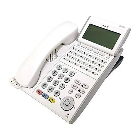
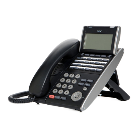
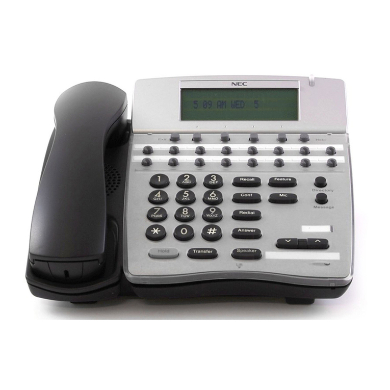
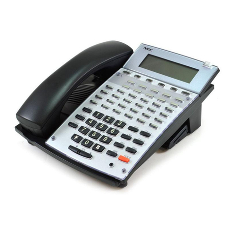
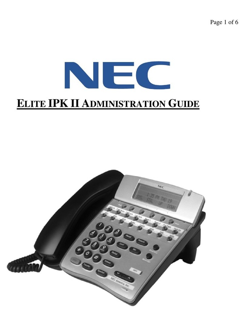
NEC DT920 User manual

LIABILITY DISCLAIMER
NEC Platforms, Ltd. reserves the right to change the specifications, functions, or
features, at any time, without notice.
NEC Platforms, Ltd. has prepared this document for use by its employees and
customers. The information contained herein is the property of NEC Platforms,
Ltd. and shall not be reproduced without prior written approval from NEC
Platforms, Ltd. All brand names and product names on this document are
trademarks or registered trademarks of their respective companies.
Copyright 2019
NEC Platforms, Ltd.

IMPORTANT NOTICE
3
WARNING
For Customers in Australia
Telephone receivers produce magnetic fields that can attract small metallic objects such as pins or staples.
To avoid injury, do not place the handset where such objects can be picked up.

IMPORTANT NOTICE
4
NOTICE
1. Changes or modifications not expressly approved by the party responsible for compliance could
void the user's authority to operate the equipment.
2. This equipment has been tested and found to comply with the limits for a Class A digital device
pursuant to part 15 of the FCC Rules. These limits are designed to provide reasonable protection
against harmful interference when the equipment is operated in a commercial environment. This
equipment generates, uses, and can radiate radio frequency energy and if not installed and used
in accordance with the instruction manual, may cause harmful interference to radio communications.
Operation of this equipment in a residential area is likely to cause harmful interference in which
case the user will be required to correct the interference at his own expense.
3. This (product and/or technology) can be utilized for development and/or manufacturing of weapons
of mass destruction. Therefore, when you (sell or provide them to any third party and/or grant
license to use), you have to take ample and necessary actions so that this (product or technology)
shall not be used for development and manufacturing of weapons of mass destruction, which would
disrupt world peace and security.
4. This product contains items subject to export regulations of U.S. When the product is exported to
other countries, prior approval by U.S. government may be required for certain countries.
5. Note that when converting this document from its original format to other file, some minor font and
format changes may occur. When viewing and printing this document, we cannot guarantee that
your specific PC or printer will support all of the fonts or graphics. Therefore, when you view the
document, fonts may be substituted and your individual printer may not have the capability to print
the document correctly.

IMPORTANT NOTICE
5
The Terms and Conditions of Software
Customers shall use the software embedded in DT920/DT530 pursuant to the terms
and conditions of software license agreement of the UNIVERGE SV9500
communication server (SLA). The software of DT920 contains certain third party open
source software components which are provided under the terms and conditions
designated at https://mind.bcom.nec.co.jp/customernet/soft-license/DT900_OSS.html .
The terms and conditions of SLA are not applied to such third party open source
software components.

IMPORTANT NOTICE
6
ABOUT THE MARKS USED IN THIS MANUAL
The following table shows the meaning of the marks used in this manual.
MARK
DESCRIPTION
DT920: Only supported with DT920 Series.
DT530: Only supported with DT530 Series.
CAUTION: The works that a user cannot perform by himself, some dangers that may cause damages to the
terminal and other cautions are described.
TIP: Useful tips when using this terminal are described.
TERMS IN THIS MANUAL
The following table shows the terms described in this manual.
TERMS
DESCRIPTION
Dial Tone
You will hear the dial tone from handset when you hang up the hand set. If you press speaker key, you will hear
the dial tone from speaker.
Special Dial Tone
If you press the transfer key while you are in conversation with calling party, you will hear the special dial tone.
Ringback Tone
When you dial an extension number, you will hear the ringback tone from handset.

CONTENTS
7
CONTENTS
INTRODUCTION ........................................................................................ 10
MODEL LINE UP OF DT920 SERIES.............................................................................10
MODEL LINE UP OF DT530 SERIES.............................................................................11
FACE LAYOUT ...............................................................................................................12
KEYS AND PARTS .........................................................................................................14
MENU..............................................................................................................................16
SIMPLE OPERATION BY MENU KEY AND CURSOR KEY ...............................17
SHORTCUT MENU ..............................................................................................17
DISPLAY.........................................................................................................................18
INSTALLATION PROCEDURE ................................................................. 19
ADJUSTING ANGLE OF TILT LEG.................................................................................19
CONNECTING LAN CABLE ................................................................................20
CONNECTING LINE CORD .................................................................................20
CONNECTING AC ADAPTER .............................................................................21
INSTALLING DIRECTORY CARD ..................................................................................21
INSTALLING/REMOVING LINE KEY CARD...................................................................22
WALL MOUNTING..........................................................................................................23
TERMINAL SETUP .................................................................................... 25
BASIC OPERATION .................................................................................. 49
TO LOG IN ...........................................................................................................49
TO LOG OUT .......................................................................................................49
TO MAKE AN EXTERNAL CALL ....................................................................................49
TO MAKE AN INTERNAL CALL......................................................................................50
TO ANSWER AN EXTERNAL CALL...............................................................................50
TO ANSWER AN INTERNAL CALL................................................................................51
MULTILINE OPERATION................................................................................................51
TO HOLD A CALL...........................................................................................................52
TO PLACE A CALL ON EXCLUSIVE HOLD...................................................................52
TO TRANSFER A CALL..................................................................................................53
SCREEN POP-UP ...............................................................................................54
FEATURE OPERATION............................................................................. 55
TO ORIGINATE A CALL USING SELECTIVE DIALING (DYNAMIC DIAL PAD, PRESET
DIAL)...............................................................................................................................55
TO ORIGINATE A CALL USING SPEED CALLING (ONE-TOUCH SPEED CALLING
KEYS)..............................................................................................................................55
TO ORIGINATE A CALL USING SPEED CALLING - SYSTEM......................................56
ONE-TOUCH SPEED CALLING SETTING USING SPDSET KEY.................................56
CONTENTS
8
TO EDIT THE REGISTERED DATA ...............................................................................57
FORCED ACCOUNT CODE...........................................................................................58
VOICE CALL...................................................................................................................59
TO ANSWER A VOICE CALL HANDS-FREE.................................................................59
CONFERENCE ...............................................................................................................61
TO ANSWER A CAMPED - ON CALL.............................................................................61
CALL WAITING - ORIGINATING ....................................................................................62
CALL PICK-UP (GROUP) ...............................................................................................63
OUTGOING TRUNK QUEUING......................................................................................63
CALL FORWARDING - BUSY LINE................................................................................65
LOGGED OUT IP STATION –CALL DESTINATION ..........................................67
TO LEAVE A MESSAGE.................................................................................................68
TO ANSWER A MESSAGE.............................................................................................69
BOSS/SECRETARY - MW LAMP CONTROL.................................................................71
BOSS SECRETARY OVERRIDE....................................................................................72
DO NOT DISTURB..........................................................................................................72
CALL REDIRECT............................................................................................................73
CALL HISTORY ON THE SYSTEM SIDE.......................................................................79
CALL HISTORY OPERATION FOR DT530 SERIES ...................... 80
TO VIEW CALL HISTORY ..............................................................................................80
TO MAKE A CALL FROM CALL HISTORY.....................................................................81
TO DELETE ALL DATA...................................................................................................81
TO DELETE SPECIFIC DATA ........................................................................................81
A CALL RECORDING ..................................................................... 82
SAVING RECORDING CALL DATA TO THE RECORDING SERVER...........................82
HEADSET OPERATION ............................................................................ 83
ATTACHING THE HEADSET..........................................................................................83
TERMINAL OPERATION USING THE HEADSET..........................................................83
HOW TO USE THE WIRELESS HEADSET....................................................................84
SPECIFICATIONS...................................................................................... 85
TECHNICAL SPECIFICATIONS .....................................................................................85
MENU LIST................................................................................................. 87
MENU LIST FOR DT920 SERIES...................................................................................87
MENU LIST FOR DT530 SERIES...................................................................................90
WEB PROGRAMMING .................................................................... 91
OUTLINE.........................................................................................................................91
TO LOG IN......................................................................................................................92

INTRODUCTION
10
INTRODUCTION
MODEL LINE UP OF DT920 SERIES
The following table shows the model line-up of DT920 series.
•ITK-6D/12D
Model Name
Description
Market
ITK-6D/12D-1
6 button /12 button (programmable keys) type Note
North America
ITK-6D/12D-1P
6 button /12 button (programmable keys) type Note
EMEA, Asia
ITK-6D/12D-1U
6 button /12 button (programmable keys) type Note
China
ITK-6DG-1A
6 button (programmable keys) type supporting Gigabit Ethernet
Australia
ITK-6DG/12DG-1P
6 button /12 button (programmable keys) type supporting Gigabit Ethernet
EMEA, Asia
ITK-6DG/12DG-1U
6 button /12 button (programmable keys) type supporting Gigabit Ethernet
China
Note : The availability of Gigabit Ethernet can be set by the terminal license setting. For details, contact the system administrator.
.

INTRODUCTION
11
MODEL LINE UP OF DT530 SERIES
The following table shows the model line-up of DT530 series.
•DTK-12D/24D
Model Name
Description
Market
DTK-12D-1
12 button (programmable keys) type
North America
DTK-12D-1P
12 button (programmable keys) type
EMEA, Asia, China
DTK-24D-1
24 button (programmable keys) type
North America
DTK-24D-1A
24 button (programmable keys) type
Australia
DTK-24D-1P
24 button (programmable keys) type
EMEA, Asia, China

INTRODUCTION
12
FACE LAYOUT
DT920 SERIES
ITK-6D
ITK-12D

INTRODUCTION
13
DT530 SERIES
DTK-24D
DTK-12D

INTRODUCTION
14
KEYS AND PARTS
This section explains keys and parts of DT920 Series using ITK-
6D as an example.
(1) Call Indicator Lamp
Lamp at the top corner flashes when a call terminates to the
terminal.
Also, when Voice Mail service is available, the Lamp lights to
indicate there has been a message.
(2) LCD
LCD (Liquid Crystal Display) provides DT Series activity
information plus date, time and soft key operation.
(3) Programmable Keys
These keys can be programmed as Flexible Line
key/Programmable Feature Key by Telephony Server
administrator.
When Telephony Server administrator sets “One-Touch Speed
Dial key” on the programmable keys, you can assign any
numbers (ex. Telephone number, etc.) to the key.
* For the assignment of the keys, contact your
Telephony Server administrator.
(4) Exit
To exit Menu or Help mode and go back to the time display.
(5) Soft Keys
Any feature shown at the bottom of the LCD is available. The
appropriate feature key is displayed on the screen according
to the call handling process.
(7) Help
Explanations of the soft keys can be displayed on the LCD by
pressing this key.
(8) Recall
Press this key to finish the call and hear the dial tone.
(9) Feature
Used to activate any features as terminal setup functions, and
to program One-Touch Speed Dial Keys.
Function Key
Feature + 0 =Side Tone On/Off (for handset)
Feature + 1 =Turns microphone on or off.
Feature + 7 =Turns call indicator lamp on or off for incoming
call notification (If turned off, this lamp will still
light to indicate message waiting.)
Feature + 8 =Selects between Normal, Dynamic Dial Pad,
and Preset Dial.
(10) Answer
When LED on this key is lit, press this key to answer an
incoming call.
(11) Mic
Press this key to respond hands-free. LED on this key lights
during speaker phone operation.
(12) Menu
To display the setting menus of terminal, such as Setting and
Config.
(13) Cursor
By using this key, user can access to various features with a
simple operation.
Also, this key is used as a cursor-movement key on the Menu
screen.
Up
Move the highlighted area one line up the
screen.
Down
Move the highlighted area one line down
the screen.
Left
Go back to the previous screen.
Right
Gotothe screenwhich corresponds to the
highlighted menu item.
Enter
Gotothe screenwhich corresponds to the
highlighted menu item.
(1)
(2)
(3)
(4)
(5)
(6)
(7)
(8)
(9)
(10)
(11)
(12)
(15)
(14)
(13)

INTRODUCTION
15
Details on Cursor Key
(a) UP/DOWN
Used to adjust LCD contrast, speaker/receiver volume, and
ringer volume.
LCD Contrast:
Press the UP/DOWN key while an idle state.
Speaker/Receiver Volume:
Press the UP/DOWN key during conversation.
Ringer Volume:
Press the UP/DOWN key during ringing.
(b) Redial
(Last Number Call, Speed Calling-Station/Group)
Press this key to activate redial feature. Press redial and
scroll back through numbers that have been dialed. When
the desired number is displayed, press the [#] or [*] key
to activate dialing.
A-law Countries [Europe, Australia, Russia, Latin America,
Middle Near East, other Asian nations]: #
μ-law Countries [North America, Hong Kong, Taiwan]:*
(c) Directory
Pressing this key opens Phonebook while the station is in
an idle state. For details on Phonebook service, see
PHONEBOOK.
(d) Enter
Use this key to display the shortcut menu (see SHORTCUT
MENU) and determine the selected item in the menu.
(14) Speaker
Controls the built-in speaker which can be used for hands-
free dialing/monitoring.
LED on the key lights when this key is active.
(15) Transfer
Allows the station user to transfer established calls to another
station, without attendant assistance.
(16) Hold
Press this key to place an internal or external call on hold.
(a)
(c)
(a)
(b)
(d)

INTRODUCTION
16
MENU
From the Menu key, you can display the configuration menu.
To Display Menu List
1.
Press Menu key while the terminal in an idle state.
The Menu List is displayed on LCD. Use Cursor
Keyto select the desired Menu Item. You can also
select the Menu Item directly using digit keys.
Main Menu for DT920 without XML application
Main Menu for DT920 with XML application
Menu Item
Digit
key to
select
Description
Service
3
To access external XML server. For
details, please contact the system
administrator.
Note: This icon appears only when XML
service is used.
Setting
4
To control settings for ringing volume,
LCD display, and music on hold. For
details, see SETUP WITH MENU KEY
FOR DT920 SERIES.
Phone
5
To switch from Main Menu to the Portal
screen provided by XML application or
Phone screen (time indication screen).
When Home URL is registered,
Portal icon appears.
When Home URL isnotregistered,
Phone icon appears.
For details, please contact the
system administrator.
Portal
XML-1
6
To display XML application 1 screen.
This icon is displayed when an XML
application starts with a new window.
Phone
Soft
Key 1
To switch from application screen to
phone screen (Time Indication
screen).
Home
Soft
Key 2
XML application screen registered in
the home URL is displayed.When the
home URL is not registered, Home
URL icon is not displayed.
Return
Soft
Key 4
To close the main menu and go back
to the previous screen.
A Portal screen is the home (entrance) screen of the phone.
When you use multiple XML applications, the URL that is
registered as the home URL is the Portal screen: this is
where other XML applications can be accessed.
To Display Menu List
Menu Item
Digit
key to
select
Description
Call History
1
To access Call History
Directory
2
To access Directory
Setting
3
To control settings for ringing
volume, LCD display, and music on
hold. For details, see SETUP WITH
MENU KEY FOR DT530 SERIES.

INTRODUCTION
17
SIMPLE OPERATION BY MENU
KEY AND CURSOR KEY
By using Menu key and Cursor key, the terminal user can access
Call History, Directory and terminal settings with simple operation.
As an example, the following operations show how to access the
Directory menu.
SHORTCUT MENU
Terminal has a Shortcut Menu for frequently-used features. You
can access to Shortcut Menu by pressing Enter key.
Shortcut Menu includes the following features.
Feature
Description
1 Missed Calls
Access to history of Missed Call.
2 Voice Mail
Access to history of incoming Voice Mail.
Press Menu key and
Select Directory menu by
using cursor key.
Call History
Directory
Settings

INTRODUCTION
18
DISPLAY
The LCD displays Icons which provide notification when events
occur.
The LCD displays RTP encryption icon which provides notification
when the conversation is encrypted.
Feature
Icon
Description
Encryption
This icon appears when the
conversation is encrypted.
This icon is displayed once per 3
seconds.
■The LCD can display the My Line information (name and
station number) when the station is in an idle state. My
Line is an actual line that is directly associated with
station number of the telephone. For the details, please
contact the system administrator.
■The icon display setting is enabled at installation. For
details, contact the system administrator.
The LCD of DT530 Series displays Icons which provide
notification when events (such as missed a call and a voice mail)
occur.
Ken Kobus [3002]
4:26 PM MON 1 JULY 2019
Mic DND >>>
Feature
Icon
Description
Missed
Call
This icon appears when there is a
missed call. Once you have checked
the missed call, this icon will disappear.
Voice
Mail
This icon provides notification of
received Voice Mail. Once you have
checked the Voice Mail, this icon will
disappear.
Cursor
This icon appears when you can do
cursor operation.
The LCD can display the My Line information (name and
station number) when the station is in an idle state. My Line
is an actual line that is directly associated with station
number of the telephone. For the details, please contact the
system administrator.
0:01:25 31300
4:26 PM MON 1 JULY 2019
MIC DND >>>
Icon Display
My Line Information
(Name and Station Number)

INSTALLATION PROCEDURE
19
INSTALLATION
PROCEDURE
ADJUSTING ANGLE OF TILT LEG
The angle of the tilt leg can be adjusted in 5 levels.
(1) First Position
(2) Second Position
(3) Third Position
(4) Forth Position
(5) Fifth Position
Raising Tilt Legs
1.
Turn the terminal over (key side down).
2.
Raise Tilt Legs to desired height.
3.
Turn the terminal over (key side up).
Lowering Tilt Legs
1.
Turn the terminal over (key side down).
2.
Lower Tilt Legs to desired height.
(1) Stopper
(2) Tilt Legs
3.
Turn the terminal over (key side up).
(1)
(2)
(3)
(4)
(5)
Tilt Leg
(1)
(2)

INSTALLATION PROCEDURE
20
CONNECTING LAN CABLE
(1) LAN Cable connector for PC (PCPort)
(2) LAN Cable connector for thepremises
(3) LAN Cable
(4) Groove
(5) Terminal
1.
Connect LAN cable to LAN cable connector (LAN
(=)) of theterminal.
2.
Press the LAN cable into the groove.
■The availability of Gigabit Ethernet depends on the
terminal license setting or the terminal model. For
details, contact the system administrator.
■1000 BASE-T is available when Gigabit Ethernet is
enabled.
CONNECTING LINE CORD
1.
Insert a Line cord plug into the Line connector on
the back of the telephone set until you hear it
click.
2.
Thread the line cord through the groove on the
back of the telephone.
3.
Lead the line cord out through the groove on the
tilt leg as shown in the figure below.
(1)
(2)
(3)
(4)
(5)
Other manuals for DT920
1
This manual suits for next models
16
Table of contents
Other NEC Telephone manuals

NEC
NEC XEN IPK ANALOGUE TELEPHONE User manual

NEC
NEC Elite IPK User manual

NEC
NEC Univerge SV9100 User manual

NEC
NEC Univerge SV8100 User manual

NEC
NEC DS2000 IntraMail Owner's manual

NEC
NEC Aspila Topaz User manual

NEC
NEC Univerge SV9100 Owner's manual

NEC
NEC Univerge SV8100 User guide

NEC
NEC NEC Dterm Series E User manual

NEC
NEC Univerge SV9100 User manual