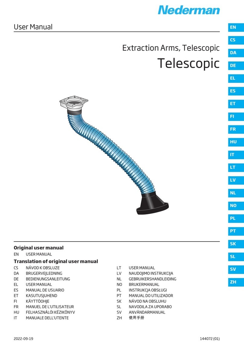
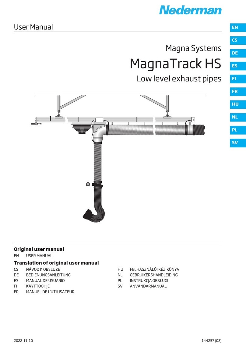
Nederman SYSTEM 920 Product information sheet

User Manual
ExhaustRail System 920
ExhaustRail Touchless
Originaluser manual
EN USER MANUAL
Translation of originaluser manual
DE BED ENUNGSANLE TUNG
ES MANUAL DE USUAR O
FR MANUEL DE L'UT L SATEUR
NL GEBRU KERSHANDLE D NG
PL NSTRUKCJA OBSŁUG
SV ANVÄNDARMANUAL
2022-11-15 144231 (04)
EN
DE
ES
FR
NL
PL
SV

ExhaustRail Touchless
Trace back information:
Workspace Main version a70
Checked in 2022-11-15
Skribenta version 5.5.022

ExhaustRail Touchless
Declaration of Conformity ........................................................ 4
Figures .......................................................................................... 7
English ........................................................................................... 10
Deutch ........................................................................................... 15
Español .......................................................................................... 20
Français ......................................................................................... 25
Nederlands ................................................................................... 30
Polski ............................................................................................. 35
Svenska ......................................................................................... 40
3

ExhaustRail Touchless
Declaration of Conformit
EN English
Declaration of Conformit
We, AB Ph. Nederman & Co., declare under our sole responsibility that
the Nederman product:
ExhaustRail Touchless (Part No. **, and stated versions of **) to which
this declaration relates, is in conformity with all the relevant provisions
of the following directives and standards:
Directives
2006/42/EC
Standards
EN SO 12100:2010, EN SO 20607:2019.
The name and signature at the end of this document is the person re-
sponsible for both the declaration of conformity and the technical file.
DE Deutch
Konformitätserklärung
Wir, AB Ph. Nederman & Co., erklären in alleiniger Verantwortung, dass
das Nederman Produkt:
ExhaustRail Touchless (Art.-Nr. **, und bauartgleiche Versionen **),
auf welches sich diese Erklärung bezieht, mit allen einschlägigen Be-
stimmungen der folgenden Richtlinien und Normen übereinstimmt:
Richtlinien
2006/42/EC
Standards
EN SO 12100:2010, EN SO 20607:2019.
Der Name und die Unterschrift am Ende dieses Dokuments sind die für
die Konformitätserklärung und die technischen Unterlagen verant-
wortlichen Personen.
ES Español
Declaración de Conformidad
Nosotros, AB Ph. Nederman & Co., declaramos bajo nuestra exclusiva
responsabilidad que el producto de Nederman,
ExhaustRail Touchless (Ref. n.º ** y las versiones indicadas de **), al
que hace referencia esta declaración, cumple con todas las provisiones
relevantes de las Directivas y normas que se indican a continuación:
Directivas
2006/42/EC
Normas
EN SO 12100:2010, EN SO 20607:2019.
El nombre y firma que figuran al final de este documento corresponden
a la persona responsable, tanto de la declaración como de la ficha técni-
ca.
FR Français
Déclaration de Conformité
Nous, AB Ph. Nederman & Co., déclarons sous notre seule responsabili-
té que le produit Nederman :
ExhaustRail Touchless (réf. ** et versions indiquées de **) auquel fait
référence la présente déclaration est en conformité avec toutes les dis-
positions applicables des directives et normes suivantes :
Directives
2006/42/EC
Normes
EN SO 12100:2010, EN SO 20607:2019.
Le nom et la signature à la fin de ce document sont ceux de la personne
responsable de la déclaration de conformité et du fichier technique.
NL Nederlands
Conformiteitsverklaring
Wij ,AB Ph. Nederman & Co., verklaren onder onze verantwoordelijkheid
dat het Nederman product:
ExhaustRail Touchless (artikelnr. **, en vermelde uitvoeringen van **)
waarop deze verklaring betrekking heeft, in overeenstemming is met
alle relevante bepalingen van de volgende richtlijnen en normen:
Richtlijnen
2006/42/EC
Normen
EN SO 12100:2010, EN SO 20607:2019.
Naam en handtekening onder dit document zijn van degene die verant-
woordelijk is voor zowel de Verklaring van Overeenstemming als het
technische document.
PL Polski
Deklaracja Zgodności
My, AB Ph. Nederman & Co. niniejszym oświadczamy na naszą własną
odpowiedzialność, że Nederman produkt:
ExhaustRail Touchless [nr części ** oraz wskazane wersje **], który je-
st przedmiotem niniejszej deklaracji, spełnia wszystkie odpowiednie
wymagania wymienionych niżej dyrektyw i norm:
D rekt w
2006/42/EC
Norm
EN SO 12100:2010, EN SO 20607:2019.
Na końcu niniejszego dokumentu znajdują się imię i nazwisko oraz pod-
pis osoby odpowiedzialnej za deklarację zgodności oraz dokumentację
techniczną.
4

ExhaustRail Touchless
SV Svenska
Överensstämmelsedeklaration
Vi, AB Ph. Nederman & Co., förklarar under vårt fulla ansvar att Neder-
man-produkten:
ExhaustRail Touchless (artikelnummer **, och angivna versioner av **)
som denna deklaration avser, är i överensstämmelse med alla relevanta
bestämmelser i följande direktiv och standarder:
Direktiv
2006/42/EC
Standarder
EN SO 12100:2010, EN SO 20607:2019.
Namnet och signaturen i slutet av detta dokument är den person som
ansvarar för både försäkran om överensstämmelse och den tekniska fi-
len.
**
20808064, 20808164
AB Ph. Nederman & Co.
P.O. Box 602
SE-251 06 Helsingborg
Sweden
Anna Cederlund
Product Center Manager
Technical Product Management
2022-11-15
5

ExhaustRail Touchless
UK Declaration of Conformit
We, AB Ph. Nederman & Co., declare under our sole responsibility that the Nederman product:
ExhaustRail Touchless (Part No. **, and stated versions of **) to which this declaration relates, is in conformity with all the relevant
provisions of the following regulations and standards:
Relevant legislation
Supply of Machinery (Safety) Regulations 2008
Standards
EN SO 12100:2010, EN SO 20607:2019.
The name and signature at the end of this document is the person responsible for the declaration of conformity.
The UK importer is authorised and responsible to compile the technical file.
**
20808064, 20808164
AB Ph. Nederman & Co.
P.O. Box 602
SE-251 06 Helsingborg
Sweden
Anna Cederlund
Product Center Manager
Technical Product Management
2022-11-15
UK mporter:
Nederman Ltd
91 Seedlee Road,
Walton Summit Centre,
Bamber Bridge,
Preston,
Lancashire,
PR5 8AE
6

ExhaustRail Touchless
Figures
1400 mm
1030 mm
950 mm
1265 mm
3646 mm
401 mm
5046 mm
1100 mm
800 mm
A
1
4100 mm
!
2
300 mm
4100 mm
A
1100 mm
B
3
7

ExhaustRail Touchless
4
A B
5
A
B
”Klick”
6
2
2
1
7
8

ExhaustRail Touchless
A B
8 9
10 11
9

ExhaustRail Touchless
EN English
User Manual
Table of contents
Figures ............................................................................................................................................................................. 7
1 Preface ............................................................................................................................................................................ 11
2 Safety .............................................................................................................................................................................. 11
2.1 Classification of important information ......................................................................................................... 11
2.2 General safety instructions .............................................................................................................................. 11
3 Description ..................................................................................................................................................................... 12
3.1 Dimensions .......................................................................................................................................................... 12
3.2 Technical data ..................................................................................................................................................... 12
4 nstallation ...................................................................................................................................................................... 12
4.1 Delivery check ..................................................................................................................................................... 12
4.2 Rail placement .................................................................................................................................................... 12
4.3 Vertical placement ............................................................................................................................................. 12
4.4 Horizontal placement ........................................................................................................................................ 12
4.5 nstall rail sections and fan ............................................................................................................................... 13
4.6 Telescopic pipe ................................................................................................................................................... 13
4.7 nstallation checklist .......................................................................................................................................... 13
4.8 Adjusting the lifting power of the balancer .................................................................................................. 13
4.8.1 ncreasing the lifting power .............................................................................................................. 13
4.8.2 Reducing the lifting power ................................................................................................................ 13
5 Using ................................................................................................................................................................................ 13
6 Maintenance .................................................................................................................................................................. 13
7 Spare Parts ..................................................................................................................................................................... 14
7.1 Ordering spare parts .......................................................................................................................................... 14
8 Recycling ......................................................................................................................................................................... 14
10

ExhaustRail Touchless
1Preface
Thank you for using a Nederman product!
The Nederman Group is a world-leading supplier and
developer of products and solutions for the environ-
mental technology sector. Our innovative products
will filter, clean and recycle in the most demanding of
environments. Nederman's products and solutions will
help you improve your productivity, reduce costs and
also reduce the impact on the environment from in-
dustrial processes.
Read all product documentation and the product iden-
tification plate carefully before installation, use, and
service of this product. Replace documentation imme-
diately if lost. Nederman reserves the right, without
previous notice, to modify and improve its products
including documentation.
This product is designed to meet the requirements
of relevant EC directives. To maintain this status, all
installation, maintenance, and repair is to be done
by qualified personnel using only Nederman original
spare parts and accessories. Contact the nearest au-
thorized distributor or Nederman for advice on tech-
nical service and obtaining spare parts. f there are
any damaged or missing parts when the product is de-
livered, notify the carrier and the local Nederman rep-
resentative immediately.
2Safet
2.1Classification of important informa-
tion
This document contains important information that
is presented either as a warning, caution or note, ac-
cording to the following examples:
WARNING!Risk of personal injur
Warnings indicate a potential hazard to the
health and safety of personnel, and how that
hazard may be avoided.
CAUTION!Risk of equipment damage
Cautions indicate a potential hazard to the
product but not to personnel, and how that
hazard may be avoided.
NOTE!
Notes contain other information that is import-
ant for personnel.
2.2General safet instructions
WARNING!Risk of personal injur
• The system must not be used for other pur-
poses than extracting fumes.
• The system is designed for use only with sta-
tionary vehicles. The vehicle must not be
moved when the nozzle has been placed next
to the vehicle exhaust pipe.
• This product is designed for extracting fumes
from an idling vehicle. Not for continuous
high rpm testing! See allowed exhaust tem-
peratures in Section3.2Technical data.
• The system must not be used when working
on the vehicle´s fuel system, when rechar-
ging the batteries or whenever there is a risk
for inflammable dust or explosive gases.
• When working with a running engine and es-
pecially in a maintenance pit a gas detector is
recommended.
• Check that there is enough suction capacity
in the extraction unit before it is connected
to the vehicle’s exhaust pipe. f not, check the
fan impeller rotation direction and/or damper
function. f necessary check the installation
of the fan start switch.
• There is a risk of heat injuries since the tele-
scopic arm and the pin-jointed arm get hot
during high load. n such cases avoid touching
the pipe.
EN
11

ExhaustRail Touchless
EN 3Description
ExhaustRail Touchless is an efficient exhaust system for stationary trucks, cars and vans.
3.1Dimensions
See Figure1 and Figure2.
3.2Technical data
Item Dimension
Application Vehicles stationary, at right angles to the rail
Mounting height Rail 4100 mm (13 ft 6 in) recommended
Pipe diameter Ø 100 mm (4”)
Weight extraction unit complete Approximately 35 kg (77.16 lb)
Recommended airflow Approximately 600 m3/h (356 cfm)
Exhaust temperature See Section2.2General safety instructions
• ntermittently maximum 180°C (350°F)
• Continuously maximum 150°C (300°F)
Positioning • Total vertical movement 2.0 m (6.56 ft)
• Total horizontal reach 1.0 m (3.28 ft)
Recycling material See Chapter8Recycling
Material • Suction trolley: Polymer
• Nozzle: EPDM
• Telescopic pipe: Aluminium
4Installation
NOTE!
Note the mounting direction (A) in Figure1.
4.1Deliver check
f there are any damaged or missing parts when the
product is delivered, notify the carrier and the local
Nederman representative immediately.
4.2Rail placement
Before mounting the product, determine the height
and position of the rail in relation to the car lift. t is
very important to decide what vehicle lengths are
to be used with the unit. See Figure3, Figure9, Fig-
ure10, and Figure11.
4.3Vertical placement
See Figure2. The mounting height from the top of the
rail to the floor is 4100 mm. This height allows enough
free room to walk under the arm.
NOTE!
• There will not be enough room to walk un-
der the product if it is mounted at a height of
less than 4100 mm from the floor to the top
of the rail.
• f it is not possible to mount the rail at the re-
commended height of 4100 mm it may not be
possible to reach the car nozzle.
4.4Horizontal placement
See Figure3. The recommended sideways position for
the rail is A = 300 mm. t is the minimum distance from
the centre of the rail to the back end of the longest
vehicle that is to be used with the unit. B = 1100 mm is
the maximum distance for the shortest vehicle.
Follow the steps below to determine the sideways rail
position for the product.
1 Calculate the distance from the centre of the rail
to the back end of the longest vehicle that is to be
used with the unit. See Figure3.
12

ExhaustRail Touchless
2 Based on the rail position calculated in step 1, de-
termine the length of the shortest vehicle that can
be used with the unit. See Figure3.
3 f necessary, adjust the final placement of the rail
so that the maximum number of cars of different
lengths can be used with the unit.
NOTE!
For technical advice about installation, contact
Nederman.
4.5Install rail sections and fan
For installing the rail system and connecting the trol-
ley, see the manual, Mounting instructions, rail.
4.6Telescopic pipe
1 See Figure4. Fit the jointed arm together with the
nozzle to the telescopic pipe.
2 Screw two screws all the way in, until stop
(without using force), and then loosen half a turn.
CAUTION!Risk of equipment damage
Do not force the screws, they may break.
3 See Figure5. Fit the lever according to (A) and (B).
Compress all sections of the telescopic pipe to the
stop position and fasten the screw. The support
ring above the jointed arm must rest on the top
flange of the lever in order to keep the telescopic
pipe in place.
4.7Installation checklist
When the mechanical assembly and fan connection
of the system are complete, it is ready for use after
double-checking the following points.
1 Check the airflow in the nozzle opening with an
airflow indicator.
2 Check that there is enough suction capacity in
the extraction unit before it is connected to the
vehicle’s exhaust pipe. f not, check the fan im-
peller rotation direction and/or damper function.
f necessary check the installation of the fan start
switch.
3 Check the telescopic function. When required,
adjust the balancer lifting power. See Sec-
tion4.8Adjusting the lifting power of the balan-
cer.
4 Check that the suction trolley can easily be moved
in the rail.
4.8Adjusting the lifting power of the
balancer
See Figure6.
4.8.1Increasing the lifting power
• Hold the knurled wheel (A) of the balancer drum in a
steady grip and turn the balancer drum (B) clockwise
for increased lifting power.
4.8.2Reducing the lifting power
1 Pull a little cord from the balancer drum.
2 Hold the balancer drum (B) in a steady grip and re-
move one or two revolutions of the cord.
5Using
NOTE!
• The system is designed for use only with sta-
tionary vehicles. The vehicle must not be
moved when the nozzle has been placed next
to the vehicle exhaust pipe.
• Use two hands when moving the nozzle and
arm.
See Figure7.
• Press down the blue button (1) on top of the nozzle.
Move the arm and nozzle into position and then re-
lease the blue button. The joints (2) are now locked
into place.
See Figure8. The extraction unit is equipped with a
mechanical damper. The damper is closed when the
lever on the top section of the extraction unit is pulled
out and the telescopic unit is moved up to the parking
position (A). There is a stop (B) on the lever to prevent
unintentional from shutting off of the damper func-
tion.
1 Pull out the lever to pull down the telescopic unit.
The telescopic unit is balanced and will stay in the
position where it is left.
2 Check the positioning of the nozzle to make sure it
is properly positioned. The nozzle shall be placed a
bit behind the vehicle exhaust pipe. See Figure9,
Figure10 and Figure11.
6Maintenance
CAUTION!Risk of equipment damage
Use only N$e$d$e$r$m$a$n$ original spare parts and ac-
cessories.
Check the following points, regarding fixing, function-
ing or wear, at periodic intervals but at least annually
or when replacing parts.
1 Rail
2 Trolley stop
3 Wheels of the suction trolley.
4 Check that the suction trolley moves easily in the
whole length of the rail.
5 Check the guideway of the suction trolley regard-
ing wear. Clean the guideway if necessary.
6 Check the rubber buffer of the suction trolley.
7 Check that there are no cracks around the wheel
carriers of the suction trolley.
8 The nozzle
9 Check that there is enough suction power in the
nozzle.
EN
13

ExhaustRail Touchless
EN 10 Check the damper function.
11 Check the telescopic function with regard to bal-
ancing, noise, and friction.
12 The cord on the balancer at least once every 6
months. See Section4.8Adjusting the lifting
power of the balancer.
13 Check the operation of the balancer. Check that
the telescopic arm lifts up properly. f necessary,
adjust the lifting power of the balancer. See Sec-
tion4.8Adjusting the lifting power of the balan-
cer. Begin by trying in the top or zero position first.
f the telescopic unit falls down, the lifting power
must be increased. The telescopic unit must be
balanced in all positions with the pin-jointed arm
in a vertical position.
14 Check the fixing of the rail brackets.
7Spare Parts
CAUTION!Risk of equipment damage
Use only N$e$d$e$r$m$a$n$ original spare parts and ac-
cessories.
Contact your nearest authorized distributor or
N$e$d$e$r$m$a$n$ for advice on technical service or
if you require help with spare parts. See also
w$w$w$.$n$e$d$e$r$m$a$n$.$c$o$m$.
7.1Ordering spare parts
When ordering spare parts always state the following:
• The part number and control number (see the
product identification plate).
• Detail number and name of the spare part (see
w$w$w$.$n$e$d$e$r$m$a$n$.$c$o$m$/$e$n$/$s$e$r$v$i$c$e$/$s$p$a$r$e$-$p$a$r$t$-
$s$e$a$r$c$h$).
• Quantity of the parts required.
8Rec cling
The product has been designed for component mater-
ials to be recycled. Different material types must be
handled according to relevant local regulations. Con-
tact the distributor or$N$e$d$e$r$m$a$n$ if uncertainties arise
when scrapping the product at the end of its service
life.
14

ExhaustRail Touchless
Deutch
Bedienungsanleitung
Inhaltsverzeichnis
Abbildungen ................................................................................................................................................................... 7
1 Vorwort ........................................................................................................................................................................... 16
2 Sicherheit ........................................................................................................................................................................ 16
2.1 Klassifizierung wichtiger nformationen ....................................................................................................... 16
2.2 Allgemeine Sicherheitshinweise .................................................................................................................... 16
3 Beschreibung ................................................................................................................................................................. 17
3.1 Abmessungen ..................................................................................................................................................... 17
3.2 Technische Daten .............................................................................................................................................. 17
4 nstallation ...................................................................................................................................................................... 17
4.1 Kontrolle der angelieferten Ware ................................................................................................................... 17
4.2 Anordnung der Schiene .................................................................................................................................... 17
4.3 Vertikale Platzierung ......................................................................................................................................... 17
4.4 Horizontale Platzierung .................................................................................................................................... 17
4.5 nstallation von Schienensektionen und Gebläse ........................................................................................ 18
4.6 Teleskoprohr ....................................................................................................................................................... 18
4.7 Checkliste nstallation ....................................................................................................................................... 18
4.8 Anpassen der Hubkraft des Balancers ........................................................................................................... 18
4.8.1 Erhöhen der Hubkraft ......................................................................................................................... 18
4.8.2 Senken der Hubkraft ........................................................................................................................... 18
5 Gebrauch ......................................................................................................................................................................... 18
6 Wartung .......................................................................................................................................................................... 18
7 Ersatzteile ....................................................................................................................................................................... 19
7.1 Bestellung von Ersatzteilen ............................................................................................................................. 19
8 Entsorgung ..................................................................................................................................................................... 19
DE
15

ExhaustRail Touchless
DE
1Vorwort
Danke, dass Sie ein Nederman-Produkt verwenden!
Die Nederman-Gruppe ist ein weltweit führender An-
bieter und Entwickler von Produkten und Lösungen
für den Umwelttechnologiesektor. Unsere innovati-
ven Produkte filtern, reinigen und recyceln auch in
den anspruchsvollsten Umgebungen. Die Produkte
und Lösungen von Nederman helfen hnen, hre Pro-
duktivität zu verbessern, Kosten zu senken und auch
die Auswirkungen industrieller Prozesse auf die Um-
welt zu reduzieren.
Lesen Sie vor nstallation, Benutzung und Wartung
dieses Produkts sämtliche Produktdokumentation
sowie das Typenschild für dieses Produkt. Bei einem
Verlust muss die Dokumentation sofort ersetzt wer-
den. Nederman behält sich das Recht vor, Produkte
und Dokumentation ohne vorherige Ankündigung zu
ändern.
Dieses Produkt erfüllt die Anforderungen der ein-
schlägigen EU-Richtlinien. Um diesen Status zu wah-
ren, müssen sämtliche nstallations-, Wartungs- und
nstandsetzungsarbeiten von qualifiziertem Perso-
nal und ausschließlich mit Original-Ersatzteilen durch-
geführt werden. Wenden Sie sich für Hilfestellung zu
technischem Service und für Ersatzteile bitte an h-
ren Fachhändler oder direkt an Nederman. Wenn Sie
bei Anlieferung des Produktes feststellen, dass Teile
beschädigt sind oder fehlen, informieren Sie bitte die
Spedition und hre Nederman Niederlassung vor Ort.
2Sicherheit
2.1Klassifizierung wichtiger Informa-
tionen
Dieses Dokument enthält wichtige nformationen, die
in Form von Warnungen und Hinweisen gegeben wer-
den:
WARNUNG!Verletzungsgefahr
Warnungen weisen auf eine mögliche Gefahr
für die Gesundheit und die Sicherheit der Be-
nutzer sowie auf die Gefahrenvermeidung hin.
VORSICHT!Gefahr der Anlagenbeschädi-
gung
Vorsichtshinweise kennzeichnen eine mögli-
che Gefahr für das Produkt, jedoch nicht für das
Personal, und enthalten nformationen zur Ge-
fahrenvermeidung.
BEACHTEN!
Hinweise enthalten wichtige nformationen für
die Mitarbeiter.
2.2Allgemeine Sicherheitshinweise
WARNUNG!Verletzungsgefahr
• Das System darf ausschließlich für das Ab-
saugen von Dämpfen verwendet werden.
• Das System ist ausschließlich für den Einsatz
mit stehenden Fahrzeugen vorgesehen. Das
Fahrzeug darf nicht bewegt werden, wenn
die Düse an das Abgasrohr des Fahrzeuges
angeschlossen ist.
• Dieses Produkt ist für die Absaugung von Ab-
gasen eines Fahrzeugs im Leerlauf bestimmt.
Nicht für Dauertests bei hohen Drehzahlen!
Siehe zulässige Abgastemperaturen in Ab-
schnitt3.2Technische Daten.
• Das System darf nicht bei Arbeiten an der
Kraftstoffanlage des Fahrzeugs, beim Laden
der Batterien und auch nicht dann verwen-
det werden, wenn Gefahr durch brennbaren
Staub oder explosive Gase besteht.
• Bei Arbeiten mit laufendem Motor und be-
sonders bei Arbeiten in Wartungsgruben wird
ein Gasmelder empfohlen.
• Überprüfen, ob die Absaugleistung am
Schlauch ausreicht. Falls keine ausreichen-
de Leistung erzielt wird, die Drehrichtung des
Ventiltors und die Funktion der Verschluss-
klappe prüfen. Den Schlauch auf Löcher un-
tersuchen.
• Gefahr von Verbrennungen! Es besteht Ver-
brennungsgefahr, da sowohl Teleskoparm
als auch Gelenkarm bei hoher Last heiß wer-
den. n solchen Fällen ein Berühren des Roh-
res vermeiden.
16

ExhaustRail Touchless
3Beschreibung
ExhaustRail Touchless ist ein effizientes Auspuffsystem für Lkw, Pkw und Transporter im Stand.
3.1Abmessungen
Siehe Abb. 1 und 2.
3.2Technische Daten
Artikel Dimension
Anwendung Fahrzeuge, stehend; rechtwinklig zur Schiene
Montagehöhe Empfehlung: Schiene 4100 mm (13 ft 6 in)
Rohrdurchmesser Ø 100 mm (4”)
Gewicht Absaugeinheit komplett ca. 35 kg (77.16 lb)
Empfohlener Luftstrom ca. 35 kg (77.16 lb)
Abgastemperatur Siehe Abschnitt2.2Allgemeine Sicherheitshinweise
• ntermittierend maximal 180°C (350°F)
• Dauernd maximal 150°C (300°F)
Positionierung • Gesamtbewegung total 2.0 m (6.56 ft)
• Gesamtreichweite waagerecht 1.0 m (3.28 ft)
Recyclingmaterial Siehe Kapitel8Entsorgung
Material • Absaugwagen: Polymer
• Tülle
• Teleskoprohr: Aluminium
4Installation
BEACHTEN!
Die Montagerichtung (A) in Abbildung1 beach-
ten.
4.1Kontrolle der angelieferten Ware
Wenn bei der Anlieferung Teile beschädigt sind oder
fehlen, sind unverzüglich der Spediteur und hre Ne-
derman-Vertretung zu benachrichtigen.
4.2Anordnung der Schiene
Bestimmen Sie vor der Montage des Produkts die Hö-
he und Position der Schiene in Bezug auf die Fahr-
zeughebebühne. Es ist sehr wichtig zu entscheiden,
welche Fahrzeuglängen mit dem Gerät verwendet
werden sollen. Siehe Abbildung3, Abbildung9, Abbil-
dung10 und Abbildung11.
4.3Vertikale Platzierung
Siehe Abbildung2. Die Montagehöhe von der Ober-
kante der Schiene bis zum Boden beträgt 4100 mm.
Diese Höhe lässt genügend Freiraum zum Gehen un-
ter dem Arm.
BEACHTEN!
• Es ist nicht genügend Platz vorhanden, um
unter dem Produkt hindurchzugehen, wenn
es in einer Höhe von weniger als 4100 mm
vom Boden bis zur Oberkante der Schiene
montiert ist.
• Wenn es nicht möglich ist, die Schiene auf der
empfohlenen Höhe von 4100 mm zu montie-
ren, ist es möglicherweise nicht möglich, die
Fahrzeugdüse zu erreichen.
4.4Horizontale Platzierung
Siehe Abbildung 2. Die empfohlene Position für die
Schiene ist A = 300mm. Das ist der Mindestabstand
von der Schienenmitte zum hinteren Ende des längs-
ten Fahrzeugs, für das die Einheit vorgesehen ist. B =
1100 mm ist der Höchstabstand für das kürzeste Fahr-
zeug.
DE
17

ExhaustRail Touchless
DE
Befolgen Sie die nachstehend angegebenen Schritte
zur Festlegung der Schienenposition für das Absaug-
kanalsystem 920 Touchless:
1 Berechnen Sie den Abstand von der Schienenmit-
te zum hinteren Ende des längsten Fahrzeugs, für
das die Einheit vorgesehen ist. Siehe Abbildung
2A.
2 Ausgehend von der in Schritt 1 berechneten
Schienenposition ermitteln Sie die Länge des kür-
zesten Fahrzeugs, das mit der Einheit verwendet
werden kann. Siehe Abbildung 2B.
3 Ggf. die endgültige Position der Schiene so korri-
gieren, dass die Höchstanzahl an Fahrzeugen mit
unterschiedlichen Längen für diese Einheit gilt.
BEACHTEN!
Für den technischen Support bei der nstallati-
on der Einheit setzen Sie sich mit Nederman in
Verbindung.
4.5Installation von Schienensektionen
und Gebläse
nstallation des Absaugkanalsystems und Anschluss
des Absaugwagens siehe das Handbuch Montagean-
leitung, Schiene.
4.6Teleskoprohr
1 Siehe Abbildung 3. Den Gelenkarm zusammen mit
der Düse am Teleskoprohr anbringen.
2 2 Schrauben komplett eindrehen, bis zum An-
schlag (nicht zu stark drehen!), dann eine halbe
Umdrehung lockern.
VORSICHT!Gefahr der Anlagenbeschä-
digung
Die Schrauben nicht mit Gewalt eindrehen,
dann können sie brechen.
3 Siehe Abbildung 4. Den Hebel gemäß (A) und (B)
anbringen. Alle Sektionen des Teleskoprohrs an
der Stopp-Position zusammendrücken und die
Schraube festziehen. Der Stützring über dem Ge-
lenkarm muss auf dem obersten Hebelflansch auf-
liegen, damit das Teleskoprohr arretiert ist.
4.7Checkliste Installation
Nach Abschluss der mechanischen Montage und An-
schluss des Gebläses ist das System einsatzbereit, so-
bald folgende Punkte gegengeprüft wurden.
1 Luftstrom an der Tüllenöffnung mit einem Luft-
stromwächter
2 Überprüfen, ob die Absaugleistung am Schlauch
ausreicht. Falls keine ausreichende Leistung er-
zielt wird, die Drehrichtung des Ventiltors und
die Funktion der Verschlussklappe prüfen. Den
Schlauch auf Löcher untersuchen.
3 Teleskopfunktion. Ggf. die Hubkraft des Balancers
anpassen.
4 Sicherstellen, dass der Absaugwagen leichtgängig
auf der Schiene ist.
4.8Anpassen der Hubkraft des Balan-
cers
Siehe Abbildung6.
4.8.1Erhöhen der Hubkraft
• Das Rändelrad (A) der Balancer-Trommel festhalten
und die Trommel (B) im Uhrzeigersinn drehen und so
die Hubkraft erhöhen.
4.8.2Senken der Hubkraft
1 Etwas Leine von der Balancer-Trommel ziehen.
2 Die Balancer-Trommel(B) festhalten und ein bis
zwei Umdrehungen der Leine entfernen.
5Gebrauch
BEACHTEN!
• Das System ist ausschließlich für den Einsatz
mit stehenden Fahrzeugen vorgesehen. Das
Fahrzeug darf nicht bewegt werden, wenn
die Düse an das Abgasrohr des Fahrzeuges
angeschlossen ist.
• Zum Bewegen von Düse und Arm beide Hän-
de nehmen.
Siehe Abbildung7.
• Drücken Sie den blauen Knopf (1) oben auf der Dü-
se und halten Sie ihn gedrückt. Bringen Sie den Arm
und die Düse in Position und lassen Sie dann den
blauen Knopf los. Die Gelenke (2) sind nun arretiert.
Siehe Abbildung8. Die Absaugeinheit ist mit einer
mechanischen Klappe ausgerüstet. Die Klappe ist ge-
schlossen, wenn der Hebel im oberen Teil der Einheit
herausgezogen und die Teleskopeinheit in Parkpo-
sition (A) hochgefahren ist. Der Hebel hat einen An-
schlag (B), mit dem ein unbeabsichtigtes Abschalten
der Klappenfunktion verhindert wird.
1 Den Hebel heraus- und die Teleskopeinheit her-
unterziehen. Die Teleskopeinheit ist im Gleichge-
wicht und bleibt in der Position, in der sie zurück-
gelassen wurde.
2 Überprüfen Sie die Platzierung der Düse, um si-
cherzustellen, dass sie richtig positioniert ist. Die
Düse ist etwas hinter dem Auspuffrohr des Fahr-
zeugs zu platzieren. Siehe Abbildung9, Abbil-
dung10 und Abbildung11.
6Wartung
VORSICHT!Gefahr der Anlagenbeschädi-
gung
Verwenden Sie ausschließlich Originalersatz-
teile und Zubehör von N$e$d$e$r$m$a$n$.
Überprüfen Sie folgende Teile in regelmäßigen Ab-
ständen, aber mindestens einmal pro Jahr oder beim
18

ExhaustRail Touchless
Austausch von Teilen, auf Befestigung, Funktion und
Verschleiß.
1 Schiene
2 Absaugwagen-Stopp
3 Räder des Absaugsschlittens.
4 Sicherstellen, dass der Absaugwagen sich über die
gesamte Schienenlänge Spur hinweg leicht be-
wegt.
5 Die Führung des Absaugwagens auf Verschleiß
kontrollieren. Die Führung ggf. reinigen.
6 Gummipuffer des Absaugwagens kontrollieren.
7 Sicherstellen, dass die Bereiche um die Radträger
des Absaugwagens keine Sprünge aufweisen.
8 Düse
9 Sicherstellen, dass die Saugkraft in der Düse aus-
reichend ist.
10 Die Klappenfunktion überprüfen.
11 Die Teleskopfunktion auf Ausgewogenheit, Ge-
räusche und Reibung überprüfen.
12 Die Leine am Balancer (siehe Anpassen der Hub-
kraft des Balancers), mindestens alle 6 Monate.
13 Den Betrieb des Balancers überprüfen. Sicherstel-
len, dass der Teleskoparm einwandfrei funktio-
niert. Ggf. die Hubkraft des Balancers korrigieren
(siehe Anpassen der Hubkraft des Balancers). Zu-
erst in der obersten oder Null-Position kontrol-
lieren. Falls der Teleskoparm herunterfällt, muss
die Hubkraft erhöht werden. Die Teleskopeinheit
muss in allen Positionen mit dem Gelenkarm in
senkrechter Stellung im Gleichgewicht sein.
14 Befestigung der Schienenhalter kontrollieren.
7Ersatzteile
VORSICHT!Gefahr der Anlagenbeschädi-
gung
Verwenden Sie ausschließlich Originalersatz-
teile und Zubehör von N$e$d$e$r$m$a$n$.
Wenden Sie sich an einen autorisierten Händler oder
an N$e$d$e$r$m$a$n$, um Hilfestellung zum technischen Ser-
vice zu erhalten oder um Ersatzteile zu bestellen. Sie-
he auch w$w$w$.$n$e$d$e$r$m$a$n$.$c$o$m$.
7.1Bestellung von Ersatzteilen
Bei der Bestellung von Ersatzteilen ist immer Folgen-
des anzugeben:
• Teile- und Kontrollnummer (siehe Typenschild am
Produkt).
• Ersatzteilnummer mit Beschreibung (siehe
w$w$w$.$n$e$d$e$r$m$a$n$.$c$o$m$/$e$n$/$s$e$r$v$i$c$e$/$s$p$a$r$e$-$p$a$r$t$-
$s$e$a$r$c$h$).
• Benötigte Stückzahl.
8Entsorgung
Bei der Entwicklung des Produktes wurde auf die Re-
cyclingfähigkeit der einzelnen Komponenten geach-
tet. Die verschiedenen Materialarten sind gemäß den
einschlägigen örtlichen Bestimmungen zu entsor-
gen. Bei Unklarheiten über die korrekte Entsorgung
des Produktes wenden Sie sich an hren Händler oder
an$N$e$d$e$r$m$a$n$.
DE
19

ExhaustRail Touchless
ES
Español
Manual de Usuario
Tabla de contenidos
lustraciones ................................................................................................................................................................... 7
1 Prólogo ............................................................................................................................................................................ 21
2 Seguridad ........................................................................................................................................................................ 21
2.1 Clasificación de información importante ....................................................................................................... 21
2.2 nstrucciones generales de seguridad ........................................................................................................... 21
3 Descripción ..................................................................................................................................................................... 22
3.1 Dimensiones ....................................................................................................................................................... 22
3.2 Datos técnicos .................................................................................................................................................... 22
4 nstalación ...................................................................................................................................................................... 22
4.1 Comprobación a la entrega ............................................................................................................................... 22
4.2 Colocación del raíl ............................................................................................................................................... 22
4.3 Colocación vertical ............................................................................................................................................. 22
4.4 Colocación horizontal ........................................................................................................................................ 22
4.5 nstalación de las secciones del raíl y el aspirador ........................................................................................ 23
4.6 Tubo telescópico ................................................................................................................................................ 23
4.7 Lista de comprobación de la instalación ........................................................................................................ 23
4.8 Ajuste de la fuerza de elevación del equilibrador ......................................................................................... 23
4.8.1 Aumento de la fuerza de elevación .................................................................................................. 23
4.8.2 Reducción de la fuerza de elevación ................................................................................................ 23
5 Uso ................................................................................................................................................................................... 23
6 Mantenimiento .............................................................................................................................................................. 24
7 Piezas de repuesto ........................................................................................................................................................ 24
7.1 Solicitud de piezas de repuesto ....................................................................................................................... 24
8 Reciclaje .......................................................................................................................................................................... 24
20
Other manuals for SYSTEM 920
5
This manual suits for next models
3
Table of contents
Languages:
Other Nederman Scrubber manuals

Nederman
Nederman NEX HD User manual

Nederman
Nederman FX2 Original Series User manual

Nederman
Nederman MagnaTrack HS Product information sheet

Nederman
Nederman NEX HD User manual

Nederman
Nederman ORIGINAL 535 Series User manual

Nederman
Nederman ORIGINAL 535 Series User manual

Nederman
Nederman Telescopic User manual

Nederman
Nederman FilterBox 12M User manual

Nederman
Nederman FilterCart Advanced User manual

Nederman
Nederman WeldFilter EC10 User manual