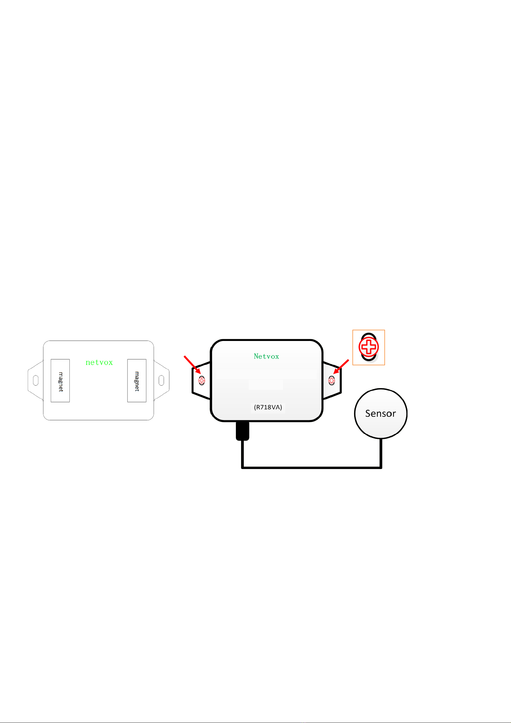
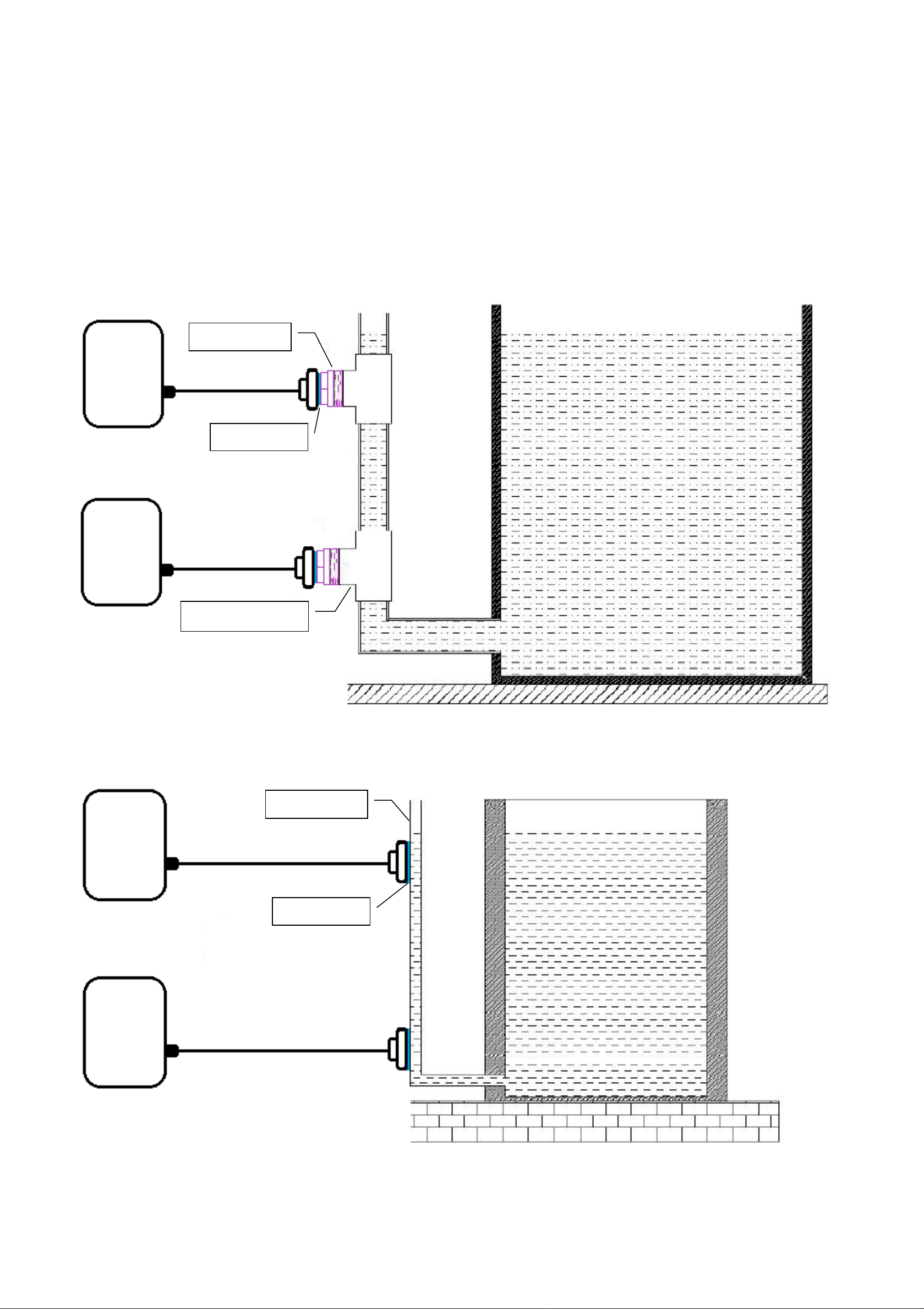
netvox R718VA User manual

Model:R718VA
Wireless Capacitive Proximity Sensor
R718VA
User Manual

1
Table of Content
1. Introduction.......................................................................................................................................................................................2
2.Appearance........................................................................................................................................................................................2
3. Main Features ...................................................................................................................................................................................3
4.Application........................................................................................................................................................................................3
5. Set up Instruction..............................................................................................................................................................................4
6. Data Report.......................................................................................................................................................................................5
7.Application Scenario.........................................................................................................................................................................8
8. Installation ........................................................................................................................................................................................8
8.1 Measured liquid medium viscosity...........................................................................................................................................8
8.2 Requirements of container and Installation Instruction ...........................................................................................................9
8.3 Adjust sensitivity ....................................................................................................................................................................12
8.4 Precautions for battery use .....................................................................................................................................................13
9. Important Maintenance Instruction ................................................................................................................................................13

2
Function Key
1. Introduction
R718VA is a device to detect the status of toilet water, hand sanitizer level, presence or absence of tissue.
This device is connected with a non-contact capacitive sensor can be mounted to the exterior of the container, without direct contact with the object to
be detected, which may detect the current water level of positions mounted, or the presence or absence of liquid soap or tissue; the detected data is
transmitted to other devices through the wireless network. It uses the SX1276 wireless communication module.
LoRa Wireless Technology:
LoRa is a wireless communication technology dedicated to long distance and low power consumption. Compared with other communication methods,
LoRa spread spectrum modulation method greatly increases to expand the communication distance. Widely used in long-distance, low-data wireless
communications. For example, automatic meter reading, building automation equipment, wireless security systems, industrial monitoring. Main
features include small size, low power consumption, transmission distance, anti-interference ability and so on.
LoRaWAN:
LoRaWAN uses LoRa technology to define end-to-end standard specifications to ensure interoperability between devices and gateways from different
manufacturers.
2. Appearance
Indicator
Capacitive Proximity Sensor

3
3. Main Features
Adopt SX1276 wireless communication module
2 ER14505 battery AA SIZE (3.6V / section) parallel power supply
Non-contact capacitive sensor
Equipment body protection grade IP65/IP67 (optional), and the sensor probe part protection grade is IP67
The base is attached with a magnet that can be attached to a ferromagnetic material object
Compatible with LoRaWANTM Class A
Frequency hopping spread spectrum technology
Configuration parameters can be configured via a third-party software platform, data can be read and alerts can be set via SMS text and email
(optional)
Applicable to third-party platforms: Actility / ThingPark / TTN / MyDevices / Cayenne
Low power consumption and long battery life
Note*:
Battery life is determined by the sensor reporting frequency and other variables.
Please refer to http://www.netvox.com.tw/electric/electric_calc.html
On this website, users can find various types of battery lifetime in different configurations.
4. Application
The water level of the toilet tank
The level of hand sanitizer
Presence or absence of tissue

4
5. Set up Instruction
On/Off
Power on Insert batteries.
(users may need a flat blade screwdriver to open)
Turn on Press and hold the function key for 3 seconds till the green indicator flashes once.
Turn off
(Restore to factory setting) Press and hold the function key for 5 seconds till the green indicator flashes for 20 times.
Power off Remove Batteries.
Note:
1. Remove and insert the battery; the device is at off state by default. Please turn on the device to use again.
2. On/off interval is suggested to be about 10 sec
onds to avoid the interference of capacitor inductance and other energy
storage components.
3. At 1st to 5th second after power on, the device will be in engineering test mode.
Network Joining
Never joined the network
Turn on the device to search the network to join.
The green indicator stays on for 5 seconds: success
The green indicator remains off: fail
Had joined the network
(Not yet restore to factory
setting)
Turn on the device to search the previous network to join.
The green indicator stays on for 5 seconds: success
The green indicator remains off: fail
Fail to join the network
(when the device is on)
First two mins: wake up every 15 seconds to send request.
After two mins: enter sleeping mode and wake up every 15 minutes to send request.
Note: Suggest to remove batteries if the device is not used to save power.
Suggest to check the device verification information on the gateway or
consult your platform server provider.
Function Key
Press and hold for 5 seconds
Restore to factory setting / Turn off
The green indicator flashes for 20 times: success
The green indicator remains off: fail
Press once The device is in the network: the green indicator flashes once and sends a report
The device is not in the network: the green indicator remains off
Sleeping Mode
The device is on and in the
network
Sleeping period: Min Interval.
When the reportchange exceeds setting value or the state changes: send a data report according to Min Interval.
The device is on but not in
the network
First two mins: wake up every 15 seconds to send request.
After two mins: enter sleeping mode and wake up every 15 minutes to send request.
Note: Suggest to remove batteries if the device is not used.
Suggest to check the device verification information on the gateway or
consult your platform server provider.
Low Voltage Warning
Low Voltage
3.2
V

5
6. Data Report
The device will immediately send a version packet report along with an uplink packet including liquid level status, battery voltage.
The device sends data in the default configuration before any configuration is done.
Default Setting:
Maximum time: 15min
Minimum time: 15min (Detect the current voltage value and liquid level status by default setting)
BatteryVoltageChange: 0x01 (0.1V)
R718VAdetection status:
The distance between liquid level and sensor reaches the threshold will report, and the threshold can adjust sensitivity
The device will detect the status regularly at the MinTime interval.
When the device detects liquid level, status = 1
When the device does not detect liquid level, status = 0
There are two conditions in which the device will report the status of the detected liquid and the battery voltage at MinTime interval:
a. When the liquid level changes from where the device can detect to where the device cannot detect. (1→0 )
b. When the liquid level changes from where the device cannot detect to where the device can detect. (0→1)
If none of the above conditions is met, the device will report at the MaxTime interval.
For the analysis of the data command reported by the device, refer to the Netvox LoRaWAN Application Command document and
http://www.netvox.com.cn:8888/page/index.
Note:
The device send data cycle depends on real programming configuration according to the customer’s inquiry.
The interval between two reports must be the minimum time.

6
Example for Report Configuration:
Fport:0x07
(1) Configure the device report parameters MinTime = 1min, MaxTime = 1min, BatteryChange = 0.1v
Downlink: 019F003C003C0100000000
The device returns:
819F000000000000000000 (The configuration succeeded)
819F010000000000000000 (The configuration failed)
(2) Read the device configuration parameters
Downlink: 029F000000000000000000
The device returns:
829F003C003C0100000000 (current configuration parameters)
Example for MinTime/MaxTime logic:
Example#1 based on MinTime = 1 Hour, MaxTime= 1 Hour, Reportable Change i.e. BatteryVoltageChange=0.1V
MaxTime MaxTime
Sleeping(MinTime) Sleeping(MinTime)
Note: MaxTime=MinTime. Data will only be report according to MaxTime (MinTime) duration regardless BatteryVoltageChange value.
Description Device CmdID DeviceType NetvoxPayLoadData
ConfigReportReq
R718VA
0x01
0x9F
MinTime
(2bytes Unit:s)
MaxTime
(2bytes Unit:s)
BatteryChange
(1byte Unit:0.1v)
Reserved
(4Bytes,Fixed 0x00)
ConfigReportRsp 0x81 Status
(0x00_success)
Reserved
(8Bytes,Fixed 0x00)
ReadConfigReportReq 0x02 Reserved
(9Bytes,Fixed 0x00)
ReadConfigReportRsp 0x82 MinTime
(2bytes Unit:s)
MaxTime
(2bytes Unit:s)
BatteryChange
(1byte Unit:0.1v)
Reserved
(4Bytes,Fixed 0x00)
Wake up and collects data
REPORTS 3.6V
Wakes up and collects data
REPORTS 3.
6
V
Wakes up and collects data
REPORTS 3.6V

7
Example#2 based on MinTime = 15 Minutes, MaxTime= 1 Hour, Reportable Change i.e. BatteryVoltageChange= 0.1V.
MaxTime
Sleeping(MinTime) sleeping sleeping sleeping
0H 15th M 30th M 45th M 1H 2H
Example#3 based on MinTime = 15 Minutes, MaxTime= 1 Hour, Reportable Change i.e. BatteryVoltageChange= 0.1V.
MaxTime
sleeping sleeping ...
0H 15th M 30th M 45th M 1H 1H 10th M 1H 25th M 1H 40th M 1H 55th M 2H 10th M
Notes :
1) The device only wakes up and performs data sampling according to MinTime Interval. When it is sleeping, it does not collect data.
2) The data collected is compared with the last data reported. If the data variation is greater than the ReportableChange value, the device reports
according to MinTime interval. If the data variation is not greater than the last data reported, the device reports according to MaxTime interval.
3) We do not recommend to set the MinTime Interval value too low. If the MinTime Interval is too low, the device wakes up frequently and the
battery will be drained soon.
4) Whenever the device sends a report, no matter resulting from data variation, button pushed or MaxTime interval, another cycle of
MinTime/MaxTime calculation is started.
Wakes up and
collects data
3.6V
Does not report
Wakes up and
collects data
3.6V
Does not report
Wakes up and
collects data
3.6V
Does not report
Wakes up and
collects data
REPORTS 3.6V
Wakes up and
collects data
REPORT 3.6V
Wakes up and
collects data
REPORTS 3.6V
Wakes up and collects data
3.5V |3.5-3.6|=0.1
REPORTS 3.5V
Wakes up and
collects data
3.5V
Does not report
Wakes up and
collects data
3.5V
Does not report
Wakes up and
collects data
3.5V
Does not report
Wakes up and
collects data 3.5V
Does not report
Wakes up and
collects data
3.5V
Does not report
Wakes up and
collects data
REPORTS 3.5V
Wakes up and
collects data
3.6V
Does not report
Users push the button,
REPORTS 3.5V.
Recalculate MaxTime.

8
7. Application Scenario
When the use case is for detecting the water level of the toilet tank, please install the device at a desired level of the toilet tank.
Turn on the device after it is fixed to the toilet tank and powered.
The device will detect the status regularly at the MinTime interval.
There are two conditions in which the device will report the status of the detected liquid and the battery voltage at MinTime interval:
a. When the liquid level changes from where the device can detect to where the device cannot detect
b. When the liquid level changes from where the device cannot detect to where the device can detect
If none of the above conditions is met, the device will report at the MaxTime interval.
8. Installation
Wireless Capacitive Proximity Sensor (R718VA) has two magnets on back.
When using it, the back of it can be adsorbed a ferromagnetic material object, or the two ends can be fixed to the wall with screws (should be
purchased)
Note:
Do not install the device in a metal shielded box or other electrical equipment around it to avoid affecting the wireless transmission of the device.
8.1 Measured liquid medium viscosity
8.1.1 Dynamic viscosity:
A. Less Than 10mPa·s when the normal measurement.
B. 10mPa < Dynamic viscosity < 30mPa·s would affect the detection
C. Greater than 30mPa·s due to a large amount of liquid attached to the container wall, cannot be measured.
Note:
With the temperature rise viscosity decreases, most of the high viscosity of the liquid by the temperature is more obvious, so when measuring
the viscosity of the liquid when the liquid temperature attention.
8.1.2 Dynamic (absolute) viscosity Explanation:
Dynamic (absolute) viscosity is the tangential force per unit area required to move one horizontal plane with respect to an other plane - at an unit
velocity - when maintaining an unit distance apart in the fluid.
Fixed with screws

9
8.1.3 Common substances
Substance Viscosity (mPa·s) Temperature (°C)
Benzene 0.604 25
Water 1.0016 20
Mercury 1.526 25
Whole milk 2.12 20
Olive oil 56.2 26
Reference source: https://en.wikipedia.org/wiki/Viscosity
8.2 Requirements of container and Installation Instruction
The tested container is divided into 3 categories: insulation materials, metal, water-absorbing non-metallic
1. Could either glue the probe or use a support to fix the probe on the outside of the container.
2. Avoid metal materials at the probe mounting site so as not to affect the detection.
3. The place where the probe is installed should avoid the liquid and the flow path of the liquid.
4. There should be no silt or other debris inside the container where the low-level probe is directly facing, so as not to affect the detection.
8.2.1 The first usage: Insulation Materials container
Containers made of non-metallic materials with flat surface, uniform thickness, tight material and good insulation performance; such as glass,
plastic, non-absorbent ceramic, acrylic, rubber and other materials or their composite materials.
Install method:
1. If the wall of the container where the measuring probe is installed is a multi-layer material, the layers should be in close contact without
bubbles or gas inter-layers. The inside and outside surfaces of the container should be flat.
2. The thickness of container: 0-20mm
3. Tank type: spherical tank, horizontal tank, vertical tank, etc.
4. The container of this kinds of materials is as following Picture 1:
Picture 1 Example of the installation method of the sensor with the non-metallic container
R718VA
R718VA
Plastic, glass, ceramics, etc. non-metallic container
Mucilage glue

10
8.2.2 The second usage: Metal container
Containers made of metal or other conductive materials; such as stainless steel iron, copper, aluminum alloy or materials with electroplated metal
layer on the surface. Because the capacitive sensor is sensitive to all conductive objects, such containers cannot be directly glued on the outside of the
container. Therefore, for containers of this type of material, it is needed to drill holes on the container, and the installation method is as follows.
Install method:
1. Prepare 2 rubber plugs and the needed tools for drilling holes.
2. Open one hole in the high position and one in low position, the hole diameter have to match the size of the rubber plug.
3. Put the rubber plug into the holes and check if there is water leakage. Add glue to seal the holes if necessary.
4. Glue the sensor on the rubber plug with glue and fix it with a support. Make sure the glue has solidified before removing the support. Example
of the installation method of the sensor with the metallic container is as follow Picture 2.
Picture 2 Example of the installation method of the sensor with the metallic container
R718VA
R718VA
Mucilage glue
Rubber plug
Copper, iron, stainless steel metal material water tower, boiler etc. metallic container

11
8.2.3 The third usage: Water absorption container
Containers made of ceramics, tiles, bricks, tiles, cement, wooden boards and other materials are insulators or weakly conductive. This type of
container without water or dry, they may not be detected when the water level sensor is approached, but when the water is filled in the container, the
wall will absorb water thus causing the container wall to become a conductor. In this case, even if the water is out of the container, the sensor will still
detect when the sensor approaches the wall of the container. If you want to use the sensor on a container of this kind of material, the installation method
should follow the “Installation method of the metal container”. For the installation method, see 8.2.2 and Picture 2, or install the sensor by external
piping. See Picture 3 and Picture 4 for example.
Picture 3 The installation example of the sensor installed on the branch tee outlet
Picture 4 The installation example of the sensor glue on the outside of the external pipeline
R718VA
R718VA
Mucilage glue
Rubber plug
Branch tee outlet
R718VA
R718VA
Mucilage glue
Rubber pipeline

12
Picture 5 The installation example of the sensor installed on the branch tee outlet of metal water pipes
Picture 6 The sensor is directly attached to the rubber tube
8.3 Adjust sensitivity
Open the back cover of the sensor head, adjust the sensitivity knob with a small screwdriver, rotate counterclockwise to increase the sensitivity, and
rotate clockwise to decrease the sensitivity (sensitivity from high to low 12 cycles in total.).
Mucilage glue
Rubber tube
R718VA
R718VA
Mucilage glue
Rubber plug
Metal water pipe

13
8.4 Precautions for battery use
Because the passivation of the ER battery electrode surface is an inherent characteristic of lithium thionyl chloride batteries, before using the
ER14505 3.6V 2400mAh lithium thionyl chloride battery, the user can use a 33 ohm resistor to activate the battery for 1 minute to actively eliminate
the battery hysteresis.
9. Important Maintenance Instruction
Kindly pay attention to the following in order to achieve the best maintenance of the product:
• Keep the device dry. Rain, moisture, or any liquid, might contain minerals and thus corrode electronic circuits. If the device gets wet, please dry it
completely.
• Do not use or store the device in dusty or dirty environment. It might damage its detachable parts and electronic components.
• Do not store the device under excessive heat condition. High temperature can shorten the life of electronic devices, destroy batteries, and deform or
melt some plastic parts.
• Do not store the device in places that are too cold. Otherwise, when the temperature rises to normal temperature, moisture will form inside, which will
destroy the board.
• Do not throw, knock or shake the device. Rough handling of equipment can destroy internal circuit boards and delicate structures.
• Do not clean the device with strong chemicals, detergents or strong detergents.
• Do not apply the device with paint. Smudges might block in the device and affect the operation.
• Do not throw the battery into the fire, or the battery will explode. Damaged batteries may also explode.
All of the above applies to your device, battery and accessories. If any device is not working properly, please take it to the nearest authorized service
facility for repair.
Other manuals for R718VA
1
Table of contents
Other netvox Accessories manuals

netvox
netvox R718F2 User manual

netvox
netvox R720FLT User manual

netvox
netvox R727 User manual

netvox
netvox R311B User manual

netvox
netvox R718CT User manual

netvox
netvox R718PQA User manual

netvox
netvox R72632A01 User manual

netvox
netvox R311A User manual

netvox
netvox R718F User manual

netvox
netvox R311LA User manual

netvox
netvox R711 User manual

netvox
netvox R718N3 User manual

netvox
netvox R718F2 User manual

netvox
netvox R315 Series User manual

netvox
netvox R712 User manual

netvox
netvox R718G User manual

netvox
netvox R718J User manual

netvox
netvox R311K User manual

netvox
netvox R311CA User manual

netvox
netvox R72615 User manual