netvox R718LB2 User manual

Model:R718LB2
Wireless 2-Gang Hall Type Open/Close Detection Sensor
Wireless 2-Gang Hall Type
Open/Close Detection Sensor
R718LB2
User Manual
Copyright©Netvox Technology Co., Ltd.
This document contains proprietary technical information which is the property of
NETVOX Technology. It shall be maintained in strict confidence and shall not be
disclosed to other parties, in whole or in part, without written permission of NETVOX
Technology. The specifications are subject to change without prior notice.

1
Table of Content
1. Introduction.................................................................................................................2
2.Appearance..................................................................................................................3
3. Main Features .............................................................................................................3
4. Set up Instruction........................................................................................................4
5. Data Report.................................................................................................................5
6. Installation ................................................................................................................10
7. Information about Battery Passivation.....................................................................13
7.1 To determine whether a battery requires activation..........................................13
7.2 How to activate the battery...............................................................................13
8. Important Maintenance Instruction ..........................................................................14

2
1. Introduction
The R718LB2 is a long-range (communication distance) Wireless 2-Gang Hall Type Open/Close
Detection Sensor for Netvox Class A type devices based on the LoRaWAN open protocol, and is
compatible with the LoRaWAN protocol.
LoRa Wireless Technology:
LoRa is a wireless communication technology famous for its long-distance transmission and low
power consumption. Compared with other communication methods, LoRa spread spectrum
modulation technique greatly extend the communication distance. It can be widely used in any use
case that requires long-distance and low-data wireless communications. For example, automatic
meter reading, building automation equipment, wireless security systems, industrial monitoring. It
has features like small size, low power consumption, long transmission distance, strong
anti-interference ability and so on.
LoRaWAN:
LoRaWAN uses LoRa technology to define end-to-end standard specifications to ensure
interoperability between devices and gateways from different manufacturers.
3
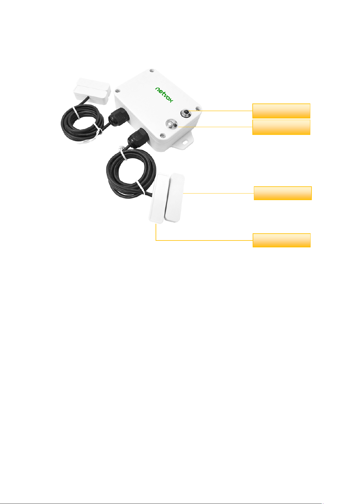
2. Appearance
3. Main Features
Compatible with LoRaWAN
2 ER14505 lithium batteries (3.6V / cell) in parallel
2-gang hall sensor detection
The base is attached with a magnet that can be attached to a ferromagnetic material object
Protection level: IP65 / IP67 (optional)
Compatible with LoRaWANTM Class A
Using frequency hopping spread spectrum technology
Configurable parameters via third-party software platform, reading data and setting alarms via
SMS text and email (optional)
Available for third-party platforms: Actility / ThingPark, / TTN / MyDevices / Cayenne
Improved power management for longer battery life
Battery Life:
⁻Please refer to web: http://www.netvox.com.tw/electric/electric_calc.html
Indicator
Function Key
Hall Sensor
Magnet

4
4. Set up Instruction
On/Off
Power on Insert batteries. (users may need a screwdriver to open)
Turn on Press and hold the function key for 3 seconds till the green indicator flashes
once.
Turn off
(Restore to factory setting)
Press and hold the function key for 5 seconds till green indicator flashes for
20 times.
Power off Remove Batteries.
Note
1. Remove and insert the battery; the device is at off state by default.
2. On/off interval is suggested to be about 10 seconds to avoid the
interference of
capacitor inductance and other energy storage components.
3. At 1st -5th second after power on, the device will be in engineering test
mode.
Network Joining
Never joined the network
Turn on the device to search the network to join.
The green indicator stays on for 5 seconds: success
The green indicator remains off: fail
Had joined the network
(not at factory setting)
Turn on the device to search the previous network to join.
The green indicator stays on for 5 seconds: success
The green indicator remains off: fail
Function Key
Press and hold for 5
seconds
Restore to factory setting / Turn off
The green indicator flashes for 20 times: success
The green indicator remains off: fail
Press once The device is in the network: green indicator flashes once and sends a report
The device is not in the network: green indicator remains off

5
The device will immediately send a version packet report along with an uplink packet including hall
sensor status and battery voltage.
The device sends data in the default configuration before any configuration is done.
Default setting:
MaxTime: Max Interval = 60 min = 3600s
MinTime: Min Interval = 60 min = 3600s
BatteryChange: 0x01 (0.1V)
Hall sensor status:
When the magnet closes to the Hall sensor, it will report the status “0”
(The distance between the magnet and the Hall sensor is less than 3cm)
When the magnet removes the Hall sensor, it will report the status “1”
(The distance between the magnet and the Hall sensor is greater than 3 cm)
Note:
The device report interval will be programmed based on the default firmware which may vary.
The interval between two reports must be the minimum time.
Please refer Netvox LoRaWAN Application Command document and Netvox Lora Command
Resolver http://loraresolver.netvoxcloud.com:8888/page/index to resolve uplink data.
Sleeping Mode
The device is on and in the
network
Sleeping period: Min Interval.
When the reportchange exceeds setting value or the state changes: send a
data report according to Min Interval.
Low Voltage Warning
Low Voltage 3.2V
5. Data Report

6
Data report configuration and sending period are as following:
Example of ConfigureCmd
FPort:0x07
Bytes 1 1 Var (Fix =9 Bytes)
CmdID DeviceType NetvoxPayLoadData
CmdID– 1 byte
DeviceType– 1 byte – Device Type of Device
NetvoxPayLoadData– var bytes (Max=9bytes)
Min. Interval
(Unit:second)
Max. Interval
(Unit:second) Reportable Change Current Change≥
Reportable Change
Current Change<
Reportable Change
Any number between
1~65535
Any number between
1~65535 Can not be 0. Report
per Min. Interval
Report
per Max. Interval
Description Device Cmd
ID Device
Type NetvoxPayLoadData
Config
ReportReq
R718LB2
0x01
0x45
MinTime
(2bytes
Unit:s)
MaxTime
(2bytes
Unit:s)
Battery
Change
(1byte
Unit:0.1v)
Reserved
(4Bytes,Fixe
d 0x00)
Config
ReportRsp 0x81 Status
(0x00_success) Reserved
(8Bytes,Fixed 0x00)
ReadConfig
ReportReq
0x02
Reserved
(9Bytes,Fixed 0x00)
ReadConfig
ReportRsp 0x82 MinTime
(2bytes
Unit:s)
MaxTime
(2bytes
Unit:s)
Battery
Change
(1byte
Unit:0.1v)
Reserved
(4Bytes,Fixe
d 0x00)

7
(1) Command Configuration:
MinTime = 1min、MaxTime = 1min、BatteryChange = 0.1v
Downlink:0145003C003C0100000000 003C(Hex) = 60(Dec)
Response:
8145000000000000000000 (Configuration success)
8145010000000000000000(Configuration failure)
(2) Read Configuration:
Downlink:0245000000000000000000
Response:
8245003C003C0100000000(Current configuration)
Example for MinTime/MaxTime logic
Example#1 based on MinTime = 1 Hour, MaxTime= 1 Hour, Reportable Change
i.e.BatteryVoltageChange=0.1V
MaxTime MaxTime
Sleeping(MinTime) Sleeping(MinTime)
Note:
MaxTime=MinTime. Data will only be report according to MaxTime (MinTime) duration
regardless BtteryVoltageChange value.
Wake up and collects data
REPORTS 3.5V
Wakes up and collects data
REPORTS 3.5V
Wakes up and collects data
REPORTS 3.6V

8
Example#2 based on MinTime = 15 Minutes, MaxTime= 1 Hour, Reportable Change
i.e. BatteryVoltageChange= 0.1V.
MaxTime
Sleeping(MinTime) sleeping sleeping sleeping
0H 15th M 30th M 45th M 1H
2H
Example#3 based on MinTime = 15 Minutes, MaxTime= 1 Hour, Reportable Change
i.e. BatteryVoltageChange= 0.1V.
MaxTime
sleeping sleeping
0H 15th M 30th M 45th M 1H 1H 10th M 1H 25th M
Notes:
(1) The device only wakes up and performs data sampling according to MinTime Interval.
When it is sleeping, it does not collect data.
Wakes up and
collects data
3.6V
Does not report
Wakes up and
collects data
3.6V
Does not report
Wakes up and
collects data
REPORT 3.6V
Wakes up and collects
data
3.5 V |3.5-3.6|=0.1
REPORTS 3.5V Wakes up and
collects data 3.5V
Does not report
Users push the button,
REPORTS 3.5V.
Recalculate MaxTime.
Wakes up and
collects data
3.6V
Does not report
Wakes up and
collects data
REPORT 3.6V
Wakes up and
collects data
3.6V
Does not report
Wakes up and
collects data
REPORT 3.6V
Wakes up and
collects data
3.5V
Does not report
Wakes up and
collects data
3.5V
Does not report
Wakes up and
collects data
3.5V
Does not report

9
(2) The data collected is compared with the last data reported. If the data change value is greater
than the ReportableChange value, the device reports according to MinTime interval.
If the data variation is not greater than the last data reported, the device reports according to
MaxTime interval.
(3) We do not recommend to set the MinTime Interval value too low. If the MinTime Interval is
too low, the device wakes up frequently and the battery will be drained soon.
(4) Whenever the device sends a report, no matter resulting from data variation, button pushed
or MaxTime interval, another cycle of MinTime/MaxTime calculation is started.
10
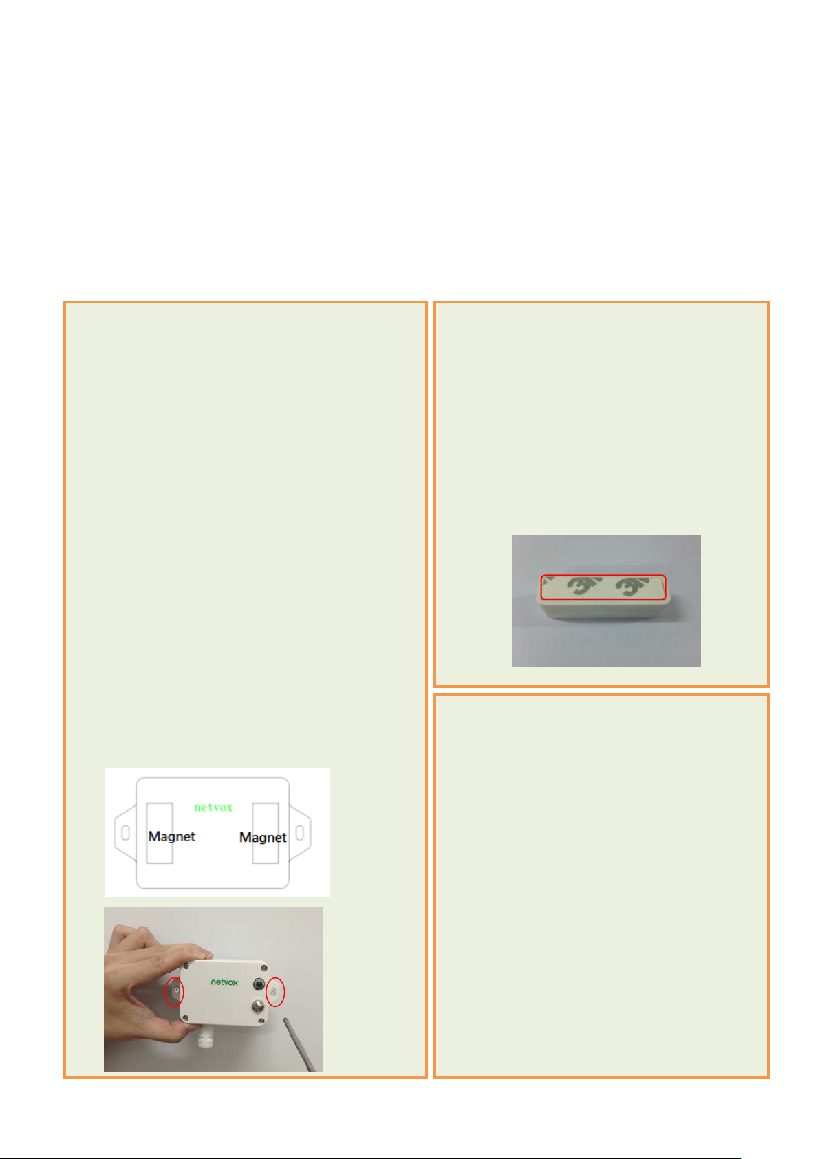
6. Installation
This device has a waterproof function. When the device is used, the back of it can be attached to the
iron surface, or two ends of it can be secured on the wall by screws.
When the magnet is close to or far away, the sensor will be triggered to send a report.
The gap between the Hall sensor and the magnet should be less than 3cm during installation.
When the installation clearance is greater than 3cm, the device will not be able to trigger the signal.
1. The Wireless 2-gang Hall Type Open/Close
Detection Sensor (R718LB2) has a built-in
magnet (see Figure 1 below).
It can be attached to the surface with iron material
during installation.
To make the installation more secure, please use
screws (purchased separately) to fix the device on
the wall or other objects (see Figure 2 below).
Comment:
Do not install the device in a metal shielded box or
in an environment surrounded by other electrical
equipment to avoid affecting the wireless
transmission of the device.
Figure 1
Figure 1
Figure 2
2. Tear off 3M release paper of Hall sensor and
the magnet then attach to the door or window
in parallel.
Note: The mounting distance between the Hall
sensor and the magnet should be less
than 3cm.
3. When the door or window is opened, the
Hall sensor is separated from the magnet,
and the Hall sensor sends status “1”.
When the door or window is closed, the Hall
sensor is close to the magnet, and the Hall
sensor device sends status “0”.

11
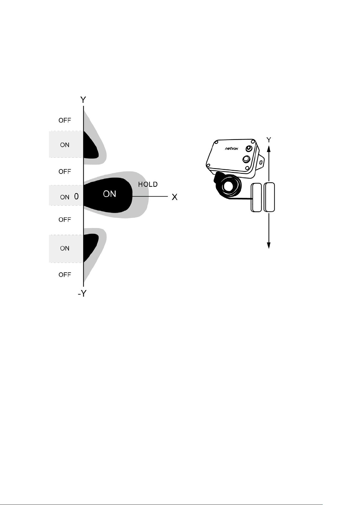
When installing the device, the magnet must move along the X axis relative to the sensor.
The Wireless 2-gang Hall Type Open/Close
Detection Sensor (R718LB2) can be used in the
following scenarios:
Door, window
Machine room door
Archives
Closet
Refrigerators and freezers
Cargo ship door
Garage Door
Public toilet door
Where you need to detect the opening and
closing status.
12
If the magnet moves along the Y axis relative to the sensor, it will cause repeated
reports due to the magnetic field.

13
7. Information about Battery Passivation
Many of Netvox devices are powered by 3.6V ER14505 Li-SOCl2 (lithium-thionyl chloride)
batteries that offer many advantages including low self-discharge rate and high energy density.
However, primary lithium batteries like Li-SOCl2 batteries will form a passivation layer as a
reaction between the lithium anode and thionyl chloride if they are in storage for a long time or if the
storage temperature is too high. This lithium chloride layer prevents rapid self-discharge caused by
continuous reaction between lithium and thionyl chloride, but battery passivation may also lead to
voltage delay when the batteries are put into operation, and our devices may not work correctly in
this situation.
As a result, please make sure to source batteries from reliable vendors, and the batteries should be
produced within the last three months.
If encountering the situation of battery passivation, users can activate the battery to eliminate the
battery hysteresis.
7.1 To determine whether a battery requires activation
Connect a new ER14505 battery to a 68ohm resistor in parallel and check the voltage of the
circuit.
If the voltage is below 3.3V, it means the battery requires activation.
7.2 How to activate the battery
a. Connect a battery to a 68ohm resistor in parallel
b. Keep the connection for 6~8 minutes
c. The voltage of the circuit should be ≧3.3V

14
8. Important Maintenance Instruction
Kindly pay attention to the following in order to achieve the best maintenance of the product:
• Keep the device dry. Rain, moisture, or any liquid, might contain minerals and thus corrode
electronic circuits. If the device gets wet, please dry it completely.
• Do not use or store the device in dusty or dirty environment. It might damage its detachable parts
and electronic components.
• Do not store the device under excessive heat condition. High temperature can shorten the life of
electronic devices, destroy batteries, and deform or melt some plastic parts.
• Do not store the device in places that are too cold. Otherwise, when the temperature rises to normal
temperature, moisture will form inside, which will destroy the board.
• Do not throw, knock or shake the device. Rough handling of equipment can destroy internal circuit
boards and delicate structures.
• Do not clean the device with strong chemicals, detergents or strong detergents.
• Do not apply the device with paint. Smudges might block in the device and affect the operation.
• Do not throw the battery into the fire, or the battery will explode. Damaged batteries may also
explode.
All of the above applies to your device, battery and accessories. If any device is not working
properly, please take it to the nearest authorized service facility for repair.
Table of contents
Other netvox Accessories manuals

netvox
netvox R718PA2 User manual

netvox
netvox R718CXAB User manual

netvox
netvox RB11E User manual

netvox
netvox R311DA User manual

netvox
netvox R313DB User manual

netvox
netvox RB11E User manual

netvox
netvox R72632A01 User manual

netvox
netvox R718PQA User manual

netvox
netvox R311CA User manual

netvox
netvox R718AD User manual

netvox
netvox R718PQA User manual

netvox
netvox Z809B User manual

netvox
netvox R718F2 User manual

netvox
netvox R718UBB Series User manual

netvox
netvox R72616A User manual

netvox
netvox R311G User manual

netvox
netvox R313M User manual

netvox
netvox R816B01 User manual

netvox
netvox R718PE01 User manual

netvox
netvox R718VA User manual


