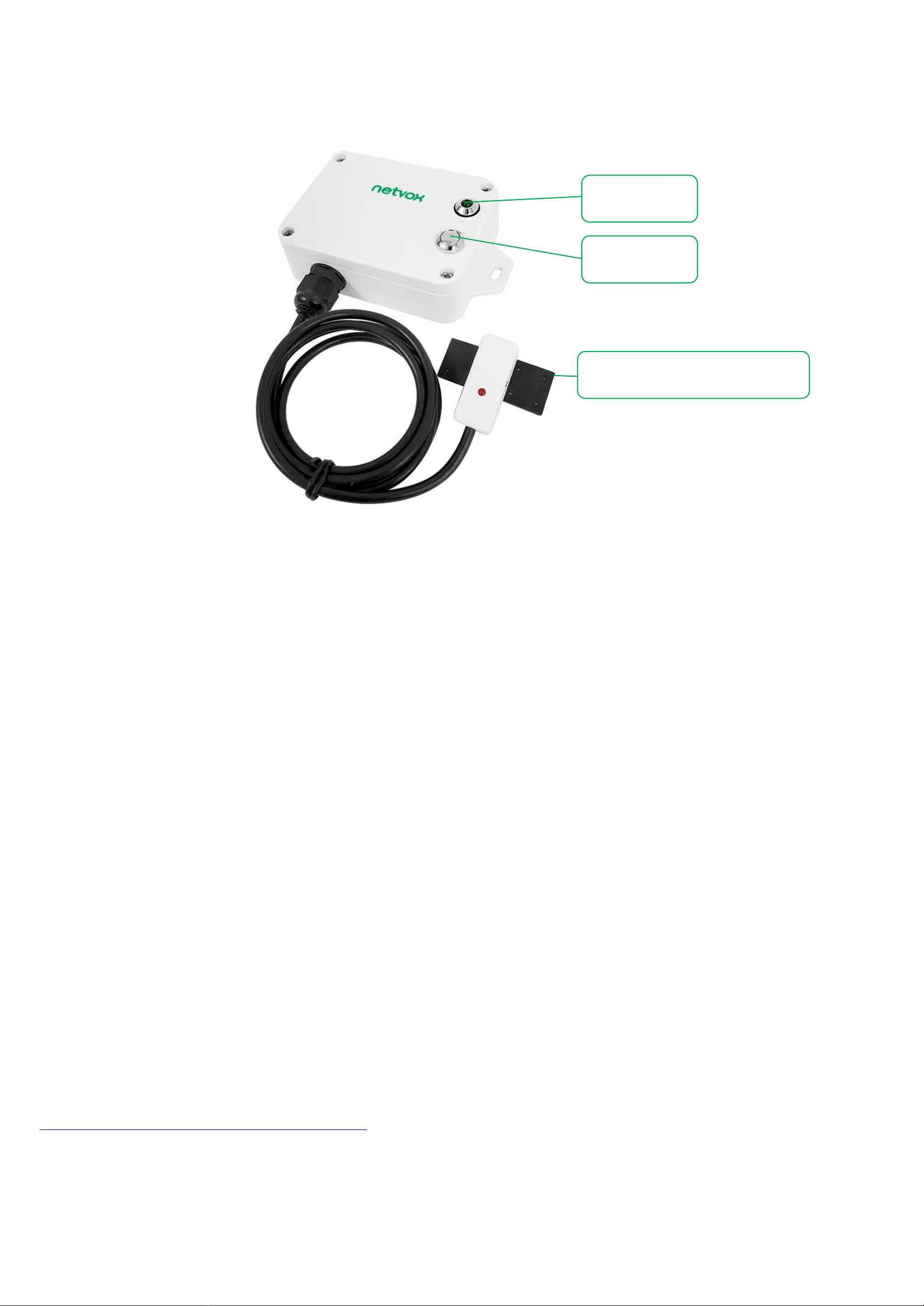
netvox R718VB User manual

Wireless Capacitive Proximity Sensor
R718VB
Wireless Capacitive Proximity Sensor
R718VB
User Manual
Copyright© Netvox Technology Co., Ltd.
This document contains proprietary technical information which is the property of NETVOX Technology. It shall be maintained in strict
confidence and shall not be disclosed to other parties, in whole or in part, without written permission of NETVOX Technology. The
specifications are subject to change without prior notice.

1
Table of Contents
1. Introduction.............................................................................................................................. 2
2. Appearance............................................................................................................................... 3
3. Features.................................................................................................................................... 3
4. Set up Instruction..................................................................................................................... 4
6. Data Report.............................................................................................................................. 5
6.1 Example of ReportDataCmd.............................................................................................. 6
6.2 Example of Report Configuration...................................................................................... 7
6.3 Example for MinTime/MaxTime logic.............................................................................. 8
7. Application............................................................................................................................... 9
8. Installation................................................................................................................................ 9
8.1 Measurement and liquid viscosity.................................................................................... 10
8.2 Containers and installation instruction..............................................................................11
8.3 Adjust sensitivity.............................................................................................................. 12
9. Information about Battery Passivation................................................................................... 12
9.1 To determine whether a battery requires activation ......................................................... 12
9.2 How to activate the battery .............................................................................................. 13
10. Important Maintenance Instruction...................................................................................... 13
11. Description of Waterproof Grade......................................................................................... 14

2
1. Introduction
R718VB is to detect the level of toilet tank water, liquid hand soap, and liquid level of non-metallic pipes (pipe outside diameter: D ≥
11MM). This device is connected to a non-contact capacitive sensor, which can be installed on the exterior of the container. Without
direct contact, the sensor can detect the current level of water or liquid hand soap within the measurement range. The collected data
could be transmitted to and displayed by other devices through the wireless network.
LoRa Wireless Technology
LoRa is a wireless communication technology dedicated to long distance and low power consumption. Compared with other
communication methods, LoRa spread spectrum modulation method greatly increases to expand the communication distance. Widely
used in long-distance, low-data wireless communications. For example, automatic meter reading, building automation equipment,
wireless security systems, industrial monitoring. Main features include small size, low power consumption, transmission distance,
anti-interference ability and so on.
LoRaWAN:
LoRaWAN uses LoRa technology to define end-to-end standard specifications to ensure interoperability between devices and
gateways from different manufacturers.

3
Function Key
2. Appearance
3. Features
⚫Non-contact capacitive sensor
⚫2 ER14505 battery AA SIZE (3.6V/section) in parallel
⚫SX1276 wireless communication module
⚫Main body: IP65/IP67 (optional); sensor probe: IP67
⚫Magnetic base
⚫LoRaWANTM Class A compatible
⚫Frequency hopping spread spectrum technology
⚫Configuration parameters can be configured through third-party software platforms, data can be read and alerts can be set via SMS
text and email (optional)
⚫Applicable to third-party platforms: Actility / ThingPark / TTN / MyDevices / Cayenne
⚫Low-power consumption and long battery life
Note: Battery life is determined by the sensor reporting frequency and other variables. Please refer to
http://www.netvox.com.tw/electric/electric_calc.html. On this website, users can find various types of battery lifetime in different
configurations.
Indicator
Capacitive Proximity Sensor

4
4. Set up Instruction
On/Off
Power on
Insert batteries. (Users may need a screwdriver to open battery case.)
Turn on
Press and hold the function key for 3 seconds until the green indicator flashes once.
Turn off (factory resetting)
Press and hold the function key for 5 seconds until the green indicator flashes for 20 times.
Power off
Remove Batteries.
Note
1. Remove and insert the battery; the device is at off state by default. Please turn on the
device to use again.
2. On/off interval is suggested to be about 10 seconds to avoid the interference of capacitor
inductance and other energy storage components.
3. At 1st to 5th second after power on, the device will be in engineering test mode.
Network Joining
Never joined the network
Turn on the device to search the network to join.
The green indicator stays on for 5 seconds: Success
The green indicator remains off: Fail
Had joined the network
(Not yet restore to factory setting)
Turn on the device to search the previous network to join.
The green indicator stays on for 5 seconds: Success
The green indicator remains off: Fail
Fail to join the network
(when the device is on)
First two mins: wake up every 15 seconds to send request.
After two mins: enter sleeping mode and wake up every 15 minutes to send request.
Note: Suggest to remove batteries if the device is not used to save power.
Suggest to check the device verification information on the gateway or
consult your platform server provider.
Function Key
Press and hold for 5 seconds
Restore to factory setting / Turn off
The green indicator flashes for 20 times: Success
The green indicator remains off: Fail
Press once
The device is in the network: the green indicator flashes once and sends a report
The device is not in the network: the green indicator remains off
Sleeping Mode
The device is on and in the
network
Sleeping period: Min Interval.
When the reportchange exceeds setting value or the state changes: send a data report
according to Min Interval.

5
The device is on but not in
the network
First two mins: wake up every 15 seconds to send request.
After two mins: enter sleeping mode and wake up every 15 minutes to send request.
Note: Suggest to remove batteries if the device is not used.
Suggest to check the device verification information on the gateway or
consult your platform server provider.
Low Voltage Warning
Low Voltage
3.2V
6. Data Report
The device will immediately send a version packet report along with an uplink packet including liquid level status, battery voltage.
The device sends data in the default configuration before any configuration is done.
Default Setting:
Maximum time: 0x384 (15min)
Minimum time: 0x384 (15min) (Detect the current voltage value and liquid level status every Min Interval)
BatteryVoltageChange: 0x01 (0.1V)
R718VB detection status:
As the device detects liquid, the device would send a report of current status and battery voltage.
The threshold could be modified through sensitivity adjustment as the distance between liquid and sensor reaches the threshold.
When the device detects liquid level, status = 1; the device does not detect liquid level, status = 0
Under two conditions, the device will report the status of the detected liquid and the battery voltage at MinTime interval:
a. When the liquid level changes from where the device can detect to where the device cannot detect. (1→0 )
b. When the liquid level changes from where the device cannot detect to where the device can detect. (0→1)
If none of the above conditions is met, the device will report at the MaxTime interval.
For the analysis of the data command reported by the device, refer to the Netvox LoRaWAN Application Command document and
http://loraresolver.netvoxcloud.com:8888/page/index
Note: The device send data cycle depends on real programming configuration according to the customer’s inquiry.
The interval between two reports must be the minimum time.

6
6.1 Example of ReportDataCmd
FPort: 0x06
Bytes
1
1
1
Var(Fix=8 Bytes)
Version
DeviceType
ReportType
NetvoxPayLoadData
Version–1 byte –0x01—the Version of NetvoxLoRaWAN Application Command Version
DeviceType–1 byte –Device Type of Device
ReportType –1 byte - the presentation of the NetvoxPayLoadData,according the devicetype
NetvoxPayLoadData–Var (Fixed =8bytes)
Tips
1. Battery Voltage:
The voltage value is bit 0 ~ bit 6, bit 7=0 is normal voltage, and bit 7=1 is low voltage.
Battery=0xA0, binary=1010 0000, if bit 7= 1, it means low voltage.
The actual voltage is 0010 0000 = 0x20 = 32, 32*0.1v =3.2v
2. Version Packet:
When Report Type=0x00 is the version packet, such as 019F000A02202108130000, the firmware version is 2021.08.13.
2. Data Packet:
When Report Type=0x01 is data packet.
Device
DeviceType
ReportType
NetvoxPayLoadData
R718VB
0x9F
0x00
SoftwareVersion
(1 Byte)
Eg.0x0A-V1.0
HardwareVersion
(1 Byte)
DateCode
(4 Byte)
eg 0x20170503
Reserved
(2 Byte, fixed 0x00)
0x01
Battery
(1Byte, unit:0.1V)
Status
(1Byte 0:off 1:on)
Reserved
(6Bytes,fixed 0x00)
Example of Uplink: 019F012400000000000000
1st byte (01): Version
2nd byte (9F): DeviceType 0x9F-R718VB
3rd byte (01): ReportType
4th byte (24): Battery-3.6v 24 Hex=36 Dec 36*0.1v=3.6v
5th byte (00): Status
6th-11th byte (000000000000): Reserved

7
6.2 Example of Report Configuration
Fport: 0x07
Bytes
1
1
Var(Fix=9 Bytes)
CmdID
DeviceType
NetvoxPayLoadData
CmdID–1 byte
DeviceType–1 byte –Device Type of Device
NetvoxPayLoadData–var bytes (Max=9bytes)
(1) Configure the device report parameters MinTime = 1min (003C), MaxTime = 1min (003C), BatteryChange = 0.1v (0x01)
Downlink: 019F003C003C0100000000
The device returns:
819F000000000000000000 (configuration succeeded)
819F010000000000000000 (configuration failed)
(2) Read the device configuration parameters
Downlink: 029F000000000000000000
The device returns:
829F003C003C0100000000 (current configuration parameters)
Description
Device
CmdID
Device
Type
NetvoxPayLoadData
ConfigReportReq
R718VB
0x01
0x9F
MinTime
(2bytes Unit:s)
MaxTime
(2bytes Unit:s)
BatteryChange
(1byte Unit:0.1v)
Reserved (4Bytes,
Fixed 0x00)
ConfigReportRsp
0x81
Status
(0x00_success)
Reserved
(8Bytes,Fixed 0x00)
ReadConfigReportReq
0x02
Reserved
(9Bytes,Fixed 0x00)
ReadConfigReportRsp
0x82
MinTime
(2bytes Unit:s)
MaxTime
(2bytes Unit:s)
BatteryChange
(1byte Unit:0.1v)
Reserved (4Bytes,
Fixed 0x00)

8
6.3 Example for MinTime/MaxTime logic
Example#1 based on MinTime = 1 Hour, MaxTime= 1 Hour, Reportable Change i.e. BatteryVoltageChange=0.1V
MaxTime MaxTime
sleeping (MinTime) sleeping (MinTime)
Note: MaxTime=MinTime. Data will only be report according to MaxTime (MinTime) duration regardless BatteryVoltageChange
value.
Example#2 based on MinTime = 15 Minutes, MaxTime= 1 Hour, Reportable Change i.e. BatteryVoltageChange= 0.1V.
MaxTime
sleeping(MinTime) sleeping sleeping sleeping
0H 15th M 30th M 45th M 1H 2H
Example#3 based on MinTime = 15 Minutes, MaxTime= 1 Hour, Reportable Change i.e. BatteryVoltageChange= 0.1V.
MaxTime
sleeping sleeping ...
0H 15th M 30th M 45th M 1H 1H 10th M 1H 25th M 1H 40th M 1H 55th M 2H 10th M
Wake up and collects data
REPORTS 3.6V
Wakes up and collects data
REPORTS 3.6V
Wakes up and collects data
REPORTS 3.6V
Wakes up and
collects data
3.6V
Does not report
Wakes up and
collects data
3.6V
Does not report
Wakes up and
collects data
3.6V
Does not report
Wakes up and
collects data
REPORTS 3.6V
Wakes up and
collects data
REPORT 3.6V
Wakes up and
collects data
REPORTS 3.5V
Wakes up and
collects data
REPORTS 3.6V
Wakes up and collects data
3.5V |3.5-3.6|=0.1
REPORTS 3.5V
Wakes up and
collects data
3.5V
Does not report
Wakes up and
collects data
3.5V
Does not report
Wakes up and
collects data
3.5V
Does not report
Wakes up and
collects data 3.5V
Does not report
Wakes up and
collects data
3.5V
Does not report
Wakes up and
collects data
3.6V
Does not report
Users push the button,
REPORTS 3.5V.
Recalculate MaxTime.

9
Notes :
1) The device only wakes up and performs data sampling according to MinTime Interval. When it is sleeping, it does not
collect data.
2) The data collected is compared with the last data reported. If the data variation is greater than the ReportableChange value,
the device reports according to MinTime interval. If the data variation is not greater than the last data reported, the device
reports according to MaxTime interval.
3) We do not recommend to set the MinTime Interval value too low. If the MinTime Interval is too low, the device wakes up
frequently and the battery will be drained soon.
4) Whenever the device sends a report, no matter resulting from data variation, button pushed or MaxTime interval, another
cycle of MinTime/MaxTime calculation is started.
7. Application
When the device is used to detect the water level of the toilet tank, please install the device at a desired level of the toilet tank.
Turn on the device after it is fixed to the toilet tank and powered. The device will detect the status regularly at the MinTime interval.
There are two conditions in which the device will report the status of the detected liquid and the battery voltage at MinTime interval:
a. When the liquid level changes from where the device can detect to where the device cannot detect
b. When the liquid level changes from where the device cannot detect to where the device can detect
If none of the above conditions is met, the device will report at the MaxTime interval.
8. Installation
Wireless Capacitive Proximity Sensor (R718VB) has two magnets on the back. When using it, the back can attach to a ferromagnetic
material, or the two ends can be fixed to the wall with screws (should be purchased)
Note:
Do not install the device in a metal shielded box or around electrical equipment or it may affect the wireless transmission of the device.
Fixed with screws

10
8.1 Measurement and liquid viscosity
8.1.1 What is dynamic viscosity?
Dynamic viscosity is the tangential force per unit area required to move one horizontal plane with respect to another plane - at
an unit velocity - when maintaining an unit distance apart in the fluid.
8.1.2 Dynamic viscosity
A.< 10mPa·s (the liquid can be measured)
B. 10mPa·s < Dynamic viscosity < 30mPa·s (the results may be affected)
C. > 30mPa·s (cannot be measured due to a large amount of liquid attached to the container wall)
Note: The viscosity decreases as the temperature rises. Liquid with high viscosity is easily affected by temperature. To get
accurate result, please mind the liquid temperature while measuring.
8.1.3 Common substances
Substance
Viscosity (mPa·s)
Temperature (°C)
Benzene
0.604
25
Water
1.0016
20
Mercury
1.526
25
Whole milk
2.12
20
Olive oil
56.2
26
Reference source: https://en.wikipedia.org/wiki/Viscosity

11
8.2 Containers and installation instruction
1. Fix the probe by glue and tapes or held by tiny shelf on the outside of the container.
2. Avoid metal materials around the probe to get accurate result.
3. The place where the probe is installed should avoid the liquid and the flow path of the liquid.
4. There should be no silt or other debris inside the container where the lower probe is directly facing, so as not to affect the
detection.
5. Containers made of non-metallic materials with flat surface, uniform thickness, tight material and good insulation performance;
such as glass, plastic, non-absorbent ceramic, acrylic, rubber and other materials or their composite materials.
Figure 1. sensor installed on square or flat non-metallic container
R718VB
Sensitivity adjustment knob
Induction sheet clings to water pipe
The induced liquid level height is related to
the sensitivity of the sensor.
The higher the sensitivity, the lower the
induced liquid level.
Note: The liquid level is detected in the upper
and lower edges of the sensing film,
which is normal.
R718VB
R718VB
Mucilage glue

12
8.3 Adjust sensitivity
1. Adjust the sensitivity knob with a small screwdriver,
2. Rotate counterclockwise to increase the sensitivity; clockwise to decrease the sensitivity
(sensitivity from high to low 12 cycles in total.)
9. Information about Battery Passivation
Many of Netvox devices are powered by 3.6V ER14505 Li-SOCl2 (lithium-thionyl chloride) batteries that offer many advantages
including low self-discharge rate and high energy density. However, primary lithium batteries like Li-SOCl2 batteries will form a
passivation layer as a reaction between the lithium anode and thionyl chloride if they are in storage for a long time or if the storage
temperature is too high. This lithium chloride layer prevents rapid self-discharge caused by continuous reaction between lithium and
thionyl chloride, but battery passivation may also lead to voltage delay when the batteries are put into operation, and our devices may not
work correctly in this situation.
As a result, please make sure to source batteries from reliable vendors, and it is suggested that if the storage period is more than one
month from the date of battery production, all the batteries should be activated. If encountering the situation of battery passivation, users
can activate the battery to eliminate the battery hysteresis.
ER14505 Battery Passivation
9.1 To determine whether a battery requires activation
Connect a new ER14505 battery to a resistor in parallel, and check the voltage of the circuit.
If the voltage is below 3.3V, it means the battery requires activation.

13
9.2 How to activate the battery
a. Connect a battery to a resistor in parallel
b. Keep the connection for 5~8 minutes
c. The voltage of the circuit should be ≧3.3, indicating successful activation.
Brand
Load Resistance
Activation Time
Activation Current
NHTONE
165 Ω
5 minutes
20mA
RAMWAY
67 Ω
8 minutes
50mA
EVE
67 Ω
8 minutes
50mA
SAFT
67 Ω
8 minutes
50mA
Note: If you buy batteries from other than the above four manufacturers, then the battery activation time, activation current, and
required load resistance shall be mainly subject to the announcement of each manufacturer.
10. Important Maintenance Instruction
Kindly pay attention to the following in order to achieve the best maintenance of the product:
• Keep the device dry. Rain, moisture, or any liquid might contain minerals and thus corrode electronic circuits. If the device gets
wet, please dry it completely.
• Do not use or store the device in dusty or dirty environment. It might damage its detachable parts and electronic components.
• Do not store the device under excessively hot condition. High temperatures can shorten the life of electronic devices, destroy
batteries, and deform or melt some plastic parts.
• Do not store the device in places that are too cold. Otherwise, when the temperature rises to normal temperature, moisture will
form inside, which will destroy the board.
• Do not throw, knock or shake the device. Rough handling of equipment can destroy internal circuit boards and delicate
structures.
• Do not clean the device with strong chemicals or detergents.
• Do not apply the device with paint. Smudges might block the device and affect the operation.
• Do not throw the battery into the fire, or the battery will explode. Damaged batteries may also explode.
All of the above applies to your device, battery, and accessories. If any device is not working properly, please take it to the nearest
authorized service facility for repair.

14
11. Description of Waterproof Grade
1. According to Enclosure Protection Class, this standard is equivalent to IEC 60529:2001 Degrees of Protection Provided by
Enclosures (IP Code).
2. The test method of IP65 waterproof grade is: spray the device in all directions under 12.5L/min water flow for 3min, and the
internal electronic function is normal.
The test method of IP67 waterproof grade is: the device is immersed in 1m deep water for 30min, and the internal electronic
function is normal.
IP65 is dust-proof and able to prevent damage caused by water from nozzles in all directions from invading electrical appliances. It
can be used in general indoor environments and sheltered outdoor environments. It is not suitable to be used in environments with
high water pressure, high temperature, high humidity, or long-time exposure to sunlight and rainstorm. If it is really necessary to
install in harsh environments, it is recommended to add rain and sun shields.
Figure 1. Install the device upside down.
Figure 2. Install the device under the rain/sun shield.
Other manuals for R718VB
1
Table of contents
Other netvox Accessories manuals

netvox
netvox ZB11C1 User manual

netvox
netvox RA0716 User manual

netvox
netvox R718PA2 User manual

netvox
netvox R816B01 User manual

netvox
netvox R718MA User manual

netvox
netvox R718EB User manual

netvox
netvox R718PA4 User manual

netvox
netvox R311FA User manual

netvox
netvox ZigBee Z801WLS User manual

netvox
netvox R311D User manual

netvox
netvox R718LB User manual

netvox
netvox R718PG-AS923 User manual

netvox
netvox RA0701 User manual

netvox
netvox R311K User manual

netvox
netvox R720FLT User manual

netvox
netvox Z713 User manual

netvox
netvox R313M User manual

netvox
netvox RA0716 User manual

netvox
netvox R313WA User manual

netvox
netvox Z808B User manual