Newstripe 4600 SP Airless User manual

4600™ SP Manual / 5124.0623
4600™ SP Airless
Product Manual

4600™ Self-Propelled Airless Sprayer
4600™ SP Manual / 5124.0623
TABLE OF CONTENTS
Precautionary Warning........................... Page 1
Assembly................................................ Page 2
Operation .............................................. Page 3
Spray Tip Cleaning.................................. Page 4
Cleaning Procedure ................................ Page 4
Cleaning Procedure (Extended Periods)...... Page 5
Cleaning Procedure (Winter Storage)......... Page 5
Maintenance .......................................... Page 5
Parts List................................................. Page 6
Engine Lubricant & Parts ........................ Page 6
Airless Pump Parts ................................. Page 7
Airless Pump Detail ................................ Page 7
Airless Spray Gun Detail ......................... Page 8
Troubleshooting Guide........................... Page 9
Warranty………………………...................... Page 10
Thank you! For your purchase of the
Newstripe 4600™ Self-Propelled
Airless Sprayer.
Please read over the instructions and
make sure that you understand the
operating procedures before using
the unit.
Please check the serial number on
your unit. This owner’s manual is
only for units with a Honda Engine,
and serial number 1025476 and
above only. For units with serial
numbers below 1025476, please
contact Newstripe for the correct
manual

4600™ Self-Propelled Airless Sprayer
ALWAYS wear safety goggles or protective eye-wear when operating the unit!
4600™ SP Manual / 5124.0623
Page 1 of 10
PRECAUTIONARY WARNING!
Please read and understand all operation instructions as
detailed in this manual. Failure to follow specified
instructions may result in equipment damage or serious
injury to personnel up to and including death!
TO BE USED ONLY WITH WATER AND OIL BASED PAINTS.
Skin Injection Hazard: High Pressure spray can inject toxins
into the blood stream. If injection occurs, seek emergency
medical treatment.
NEVER try to stop or deflect leaks with any part of your body.
ALWAYS release the pressure in the system before changing
or cleaning the spray tip.
ALWAYS use the nozzle tip guard.
ALWAYS engage the Trigger Lock on the spray gun before
removing the spray gun for hand operation.
NEVER place your hands or any body parts in front of the
spray gun.
NEVER point the spray gun at, or spray other persons or
animals.
NEVER clean the spray tip while it is attached to the spray
gun. Remove the spray tip from the gun to clean the tip
guard.
NEVER remove spray tip while cleaning the pump.
NEVER use pliers to tighten or loosen high pressure fittings
on the outlet side of the pump.
Use only in a well-ventilated area.
Always consult your Facility Safety and/or Personnel
Department for specified safety protocols prior to operating
this equipment.

4600™ Self-Propelled Airless Sprayer
ALWAYS wear safety goggles or protective eye-wear when operating the unit!
4600™ SP Manual / 5124.0623
Page 2 of 10
ASSEMBLY
1. Remove the unit from the crate and open
the packing cartons. Check for any damage
that may have occurred during shipment. If
you see any possible damage make a note
of it on the delivery paper work and advise
the factory immediately.
2. Unpack the spray gun support arm, spray
gun mounting bracket and spray shields.
3. Slide one spray shield onto the gun support
arm from each end with the star knob on
top. Snug the star knobs. (Pic 1)
4. Slide tube with shields into receiving tube
on front of machine and snug star knobs.
(Pic 1)
5. Slide the spray gun mounting bracket onto
the upright and hand tighten star knob.
(Pic 1)
6. Place the spray gun (without the hose
attached) in the holder and secure it with
the clamp. (Pic 1)
7. Check the placement of the spray gun in
the gun holder. The spray gun should be far
enough forward so that there is room
between the trigger and lifting bar (1/8”-
3/16”). This will allow the gun to shut off
completely when the trigger is released.
(Pic 1)
8. There should also be enough room to push
the trigger lock sideways. If the trigger lock
will not push, release the gun clamp and
slide gun backward until you can push the
trigger lock. Re-clamp the gun. NOTE: To
release the trigger lock: Push the trigger
lock in on the right side (outside) of the
gun. (Pic 1)
9. Attach one end of the spray hose to the pump
outlet with a ¾” wrench and the other end to
the spray gun. You will need two wrenches,
(3/4” & 9/16” or two adjustable wrenches) to
secure the hose on the spray gun as it has a
swivel fitting. Tighten both connections. (Pic 1)
10. Make sure that the static chain is
contacting the ground (Attached to the
bottom side of the chassis).
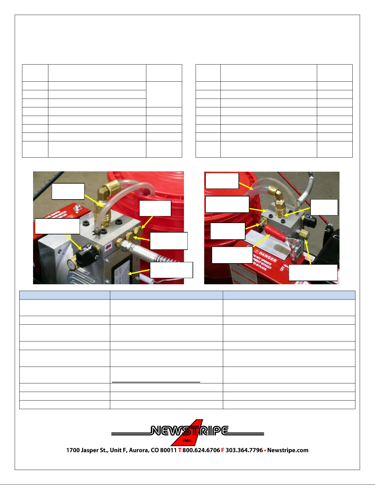
11. If the unit was shipped with the suction
hose removed from the pump (garden hose
type fitting). Depress the inlet valve stem
to ensure it moves freely. Attach the
suction hose. The hose fitting may be hand
tightened. You may also need to perform
the operation of depressing the valve stem,
any time the pump does not want to prime.
(Pic 2)
12. Always check the oil level in the engine
before starting (Full Synthetic SAE 5W30).
Pic 1
Pic2
Receiver
Tube
Trigger
Lock
Star Knob
Gun Swivel
Fitting
Spray Gun
Support
Arm
Spray
Shields
Garden
Hose Fitting

4600™ Self-Propelled Airless Sprayer
ALWAYS wear safety goggles or protective eye-wear when operating the unit!
4600™ SP Manual / 5124.0623
Page 3 of 10
OPERATION
We recommend practicing with water to learn the controls and machine operation. Then if you are going to use an oil-
based paint, you will have to flush out the water with paint thinner (mineral spirits) prior to using the oil-based paint.
ALWAYS STRAIN THE PAINT BEFORE USE!
1. Turn the black knob on the spray control valve to the
prime/ re-circulating position (arrows in a circle symbol,
in line with the arrow on the side of pump block).
2. Move pump engaging lever to the “ON” position.
3. The gold knurled knob on the pressure control valve
should be turned all the way in (turn clockwise to where
it just stops. Do not over tighten)
4. You should see liquid start to flow back to the pail in the
return hose. Let it run until there are no air bubbles in
the return hose. If the bubbles do not stop, check the
tightness of suction hose fitting at the pump. (See Notes
below)
5. Turn the black knob on the spray control valve to the
spray position. (Spray gun symbol, in line with arrow on
side of pump block).
6. Squeeze the gun trigger lever and paint or water will
spray from the gun.
7. Adjust the pressure by turning the gold pressure
control knob counter clockwise until the spray
pattern decreases, then increase the pressure by
turning it clockwise just to where you get a good
even spray pattern. You should run the system at
the lowest pressure that still gives good results to
reduce system wear.
8. Adjust the spray gun height to achieve the desired
line width.
9. To move forward, push the drive lever forward
until it locks. Speed may be controlled through the
engine throttle. To stop, pull the drive lever
backward.
10. When finished spraying or if the machine will be
left unattended for any amount of time, turn the
spray control knob to the prime/re-circulating
position, turn off engine, squeeze the gun trigger
to release the pressure from the system, and then
close the fuel shut off valve.
QR code link for
bleed procedure video
OPERATIONAL NOTE!
NOTE: If the pump does not prime, turn off the pump by moving the pump engaging
lever to the OFF position, then back out the pressure control knob several turns
(counter clockwise) until loose. Push the outlet valve button three times, and then
move the pump engaging lever to the ON position. Leave the spray control knob in
the prime/re-circulating position and let the pump run for FIVE MINUTES. Then turn
the pressure control knob back in until it stops. The pump should now prime.
NOTE: If the pump primes and air bubbles continue to appear in the hose after one
minute, the suction hose fitting may not be tight enough or the rubber washer may
be worn. Turn off the machine, turn the spray valve to the prime position and
depress the spray trigger (lever) to open the gun and release the system pressure.
Remove the garden hose fitting at the inlet side of the pump, depress inlet valve
stem to make sure it is free, inspect the washer to make sure it is seated and in
good condition. Re-attach the garden hose fitting making sure that it is tight. You
may have to lightly snug it with pliers if you continue to get air bubbles. Start the
engine and repeat first steps for operation.

4600™ Self-Propelled Airless Sprayer
ALWAYS wear safety goggles or protective eye-wear when operating the unit!
4600™ SP Manual / 5124.0623
Page 4 of 10
SPRAY TIP CLEANING DURING USE
1. Place the spray control knob in the re-circulating
position.
2. Turn the spray tip arrow on spray gun so that the
arrow points toward the gun.
3. Turn the spray control knob to the spray position
and trigger the gun. This should clear the gun. Turn
the spray control knob to the prime position and
trigger gun to release the system pressure.
4. Reverse the spray tip so that the spray tip arrow on
the spray gun points towards the ground.
5. Turn the Prime/Spray control knob to the spray and
resume spraying. If the spray gun continues to clog,
check the spray gun filter in the gun handle.
6. Turn the spray control knob to the prime position
and trigger gun to release the system pressure.
Press trigger lock on side of spray gun to lock spray
trigger and then remove the gun from holder. Push
forward on spray trigger guard to release it from
the front of the gun.
7. Using the spray trigger guard as a wrench, you can
now unscrew handle. The filter pulls straight out of
handle. Only rinse the filter to clean it. If the filter is
still clogged, collapsed, dented, or torn, replace the
filter. Reinstall the cleaned filter or a new filter. If
there are still issues, proceed to the cleaning
procedure.
CLEANING PROCEDURE
1. Remove the pail with paint.
2. Place an empty pail on the machine and fill it with 2 gallons of water (if using water based paints) or
with the appropriate solvent if using an alkyd/oil base paint so that suction filter is covered.
3. Place the pump return hose in a waste container.
4. Make sure the spray control knob is in the prime/re-circulating position.
5. Start the engine and let it run in the prime position until the fluid in the pump return hose runs clear.
6. Turn the spray control knob to the spray position.
7. Trigger the gun until the fluid spraying from the gun runs clear.
8. Turn the spray control knob to the prime/re-circulating position and then turn off the engine and
trigger the spray gun to release the system pressure.
9. Wipe down the suction tube and the pump return hose.
10. Clean the spray tip if needed with a nylon bristle brush. DO NOT USE METAL BRUSHES
PRECAUTIONARY WARNING
ALWAYS release the pressure in the system before changing or cleaning
the spray tip. (Place the Spray Control Knob in the re-circulating position,
turn off the sprayer and squeeze the spray trigger to release the pressure)
NEVER use fuels to clean the equipment
DO NOT use solvents containing halogenated hydrocarbons such as methyl
bromine, carbon tetrachloride and ethyl iodine
DO NOT attempt to clean a clogged gun filter. You must replace it.
DO NOT use brushes with metal bristles or any metal object to clean the
spray tip of dried paint. Replace the tip if it cannot be cleaned!

4600™ Self-Propelled Airless Sprayer
ALWAYS wear safety goggles or protective eye-wear when operating the unit!
4600™ SP Manual / 5124.0623
Page 5 of 10
CLEANING PROCEDURE FOR EXTENDED PERIODS OF NON-USE
1. Clean the machine as instructed in cleaning procedure.
2. Pick up the suction filter and hold it with the bottom facing up.
3. Pour 2 ounces of pump protector into the suction filter so that there is approximately 2 inches of fluid showing
in the inlet hose.
4. Leave the engine off and pull the recoil start until you see pump protector fluid in the return hose.
5. The machine may now be stored with the fluid remaining inside the hose and pump.
CLEANING PROCEDURE FOR WINTER (FREEZING) STORAGE
1. Clean the machine as instructed in the cleaning procedure and then place ½ bottle of pump protector in the pail.
2. Place spray knob in prime/re-circulate position and run the pump until the pump protector fluid is seen flowing
from the return hose.
3. Turn the spray knob to the spray position and trigger the gun until pump protector fluid sprays from the gun.
4. Turn the spray control knob to prime/re-circulate position, move the pump engaging lever to the “OFF” position
to turn off the pump, and trigger the spray gun to release the system pressure.
5. Remove as much fuel from the engine gas tank as you can.
6. Close the fuel shut-off valve and then run the engine until it runs out of gas and stops.
7. Disconnect the paint hose from pump and gun, and then drain the hose.
8. The machine may now be stored in freezing temperatures.
9. Drain and change the engine oil in the spring before using the machine.
MAINTENANCE
ITEM
CHECK
MAINTENANCE ACTION
Engine Oil
Before each use
Change the oil after the first 20 hours of
operation and then, every 100 hours.
Spark Plug & Air Filter
Every 4 Months
Clean or change as needed.
Wheels
Lubricate weekly
Grease the wheels with bearing grease.
Drive/Pump Engaging Levers & Gun Clamp
Lubricate weekly
Oil the pivot points with light machine oil.
Spray Gun Cable and Cable Clamp
Check Weekly
Lubricate with a quality dry lubricant.
Spray Gun Filter
Check Monthly
Replace if filter becomes clogged.
Spray Pump
Before and after each use
Use pump protector if the unit will not be
used for more than one day.
Suction Filter
Before each use
Replace as needed or when clogged.
Suction Tube
Before each use
Replace if needed or has cuts.
Bypass (re-circulation) hose
Before each use
Replace if needed or has cuts.
Spray Hoses
Before each use
Replace if needed or has cuts.
Spray Tip
Before each use
Replace if spray pattern is uneven or narrow.
Outlet Push Button
Before each use
Replace every 1000-1500 gallons or if leaking.
Outlet Valve
If pump does not prime
Replace every 500-1000 gallons.
Inlet Valve
If pump does not prime
Replace Every 500-1000 gallons.
Prime/Spray Valve
If pump will not toggle
between Prime/Spray
Replace every 1000-1500 gallons or if it stops
working.

4600™ Self-Propelled Airless Sprayer
ALWAYS wear safety goggles or protective eye-wear when operating the unit!
4600™ SP Manual / 5124.0623
Page 6 of 10
PARTS LIST
Item
Description
Part
Number
Item
Description
Part
Number
#1
25’ Airless Paint Hose
10000458
#18
Chassis
10004028
#2
Airless Spray Gun with 517 Tip
10005114
#19
Belt Guard
10004029
#3
Spray Gun Clamp
10005152
#20
Belt, Drive (Gates 4L310)
10002891
#4
Spray Gun Trigger Lifting Bar
N/A
#21
Belt, Pump Drive (Kevlar 4L320)
10003019
#5
Spray Gun Support Arm
10003550
#22
Star Knob (5 required)
10000007
#6
Spray Gun Mount Assembly
10004607
#23
Spray Control Lever
10002951
#7
Pivot Assembly With Shield, Right
10004825
#24
Spray Control Cable
10002517
#8
Pivot Assembly With Shield, Left
10004824
#25
Pulley, Engine
10001739
#9
Spray Tip Guard w/Base
10005116
#26
Pulley, Drive
10004027
#10
Spray gun Filter (Package of 2)
10000641
#27
Pulley, Pump Drive
10000708
#11
517 Reversible Spray Tip (2”-4” Line)
10000508
#28
Pulley, Drive Idler
10001111
#12
Drive Lever
10002072
#29
Pulley, Pump Idler
10003815
#13
Drive Rod
10004603
#30
Spring, Pump Idler
10002897
#14
Cable Adjuster
10000018
#31
Spring, Drive Belt Idler
10001756
#15
Hand Grip (2)
10004281
#32
Drive Roller (2)
10003387
#16
Handle Bars
10003762
#33
Drive Shaft Bearing (2)
10001769
#17
Handle Braces (2)
10004578
#34
Wheels, 10” Pneumatic
10000012
ENGINE LUBRICANT AND PARTS
ITEM
SPECIFICATIONS
Engine
Part Number 10000371, Honda GX120 With Oil Alert
Oil Capacity
18 Ounces (0.56 Liters) Full Synthetic 5W-30
Spark Plug
NGK Part Number BPR6ES or Denso Part Number W20EPR-U
Air Filter
Part Number 10000401
Pic4
Pic 5
Pic 6
#31 Drive
Idler Spring
#28 Drive
Idler Pulley
#25 Engine
Pulley
#21 Pump
Drive Belt
#30 Pump
Idler Spring
#32 Drive
Roller
#26 Drive
Pulley
#20 Drive
Belt
#27 Pump
Drive Pulley
#23 Spray
Control Lever
#19 Belt
Guard
#24 Spray
Control Cable
#12 Drive
Lever
#13 Drive
Rod
#1 25’ Paint Hose
#18
Chassis
#7 Right Pivot
Assy. w/Shield
#9 Tip
Guard
#4 Trigger
Lifting Bar
#2 Spray
Gun
#11
Spray Tip
#22 Star
Knob
#6 Gun
Mount
#8 Left Pivot
Assy. w/Shield
#3 Spray Gun
Clamp
#29 Pump
Idler Pulley

4600™ Self-Propelled Airless Sprayer
ALWAYS wear safety goggles or protective eye-wear when operating the unit!
4600™ SP Manual / 5124.0623
Page 7 of 10
AIRLESS PUMP PARTS
Item
Description
Part
Number
Item
Description
Part
Number
#35*
Outlet Valve
10005102
(Kit)
#42
Pump Engaging Lever
10001817
#36*
Outlet Valve Push Button
#43
Suction Hose Filter
10001760
*#35 & #36 Available in Kit Only
#44
Suction Hose Sleeve
10003932
#37
Diaphragm Kit
10000382
#45
Suction Hose
10002863
#38
Spray Pump, Airless
10000407
#46
Bypass Hose (Return)
10002862
#39
Prime/Spray Control Valve
10004000
#47
Suction Hose Washer (5 Pack)
10000711
#40
Pressure Control Knob
N/A
#48
5-Gallon Pail Strainer (5 Pack)
10003569
#41
Inlet Valve
10002745
**
Airless Pump Maintenance Kit
(Includes #26, #27, #29, #31, & #36)
10004609
AIRLESS PUMP DETAIL
ITEM
CHECK
*REPLACE
Spray Tips: 517 2”-4” Width
619 4”-6” Width
Before each use.
Every 75-500 gallons, or when the line quality
becomes poor.
Suction Filter 10001760
Before each use.
If the filter becomes clogged.
Gun Filter 10000641
Every 25 gallons or if the gun does not
spray.
REPLACE ONLY DO NOT CLEAN (every 50-250
gallons).
*Outlet Push Button 10005102
Before each use.
Every 1000-1500 gallons or if leaking.
*Inlet Valve 10002745
If the pump does not prime. Check the
hose washer at the same time.
Every 500-1000 gallons.
Washer- Every 50-250 gallons.
*Outlet valve 10005102
If the pump does not prime.
*Inlet/Outlet valve kit 10000694
Every 500-1000 gallons.
Prime/Spray Valve 10004000
Only if it stops working.
Every 1000-1500 gallons or if it stops working.
Suction Hose
Before each use check for nicks or cuts.
As needed if damaged, or clogged.
Bypass/Return Hose
Before each use check for nicks or cuts.
As needed if damaged, or clogged.
*Interval ranges may vary due to the wide variety of paint types.
#36 Inlet
Valve
#46 Bypass
Hose
#40 Pressure Valve
NEVER REMOVE
#45 Suction
Hose
#39 Prime/Spray
Valve
Pump Block Assy
NEVER REMOVE
Port for
Gauge Option
#35 Outlet
Valve
Front Cover
NEVER REMOVE
#41 Outlet
Push Button
#41
#42 Pump
Engaging Lever

4600™ Self-Propelled Airless Sprayer
ALWAYS wear safety goggles or protective eye-wear when operating the unit!
4600™ SP Manual / 5124.0623
Page 8 of 10
AIRLESS SPRAY GUN DETAIL
#
Part Number
Description
1
10005116
SPRAY TIP GUARD
2
10002103
319 SPRAY TIP - STANDARD FOR GPS AND SKID MOUNTED STRIPERS
10000508
517 SPRAY TIP - STANDARD FOR WALK BEHIND STRIPERS
10004860
519 SPRAY TIP - STANDARD TIP FOR RIDE ON STRIPERS
10003824
619 SPRAY TIP - ALLOWS FOR WIDER LINES THAN 517 & 519 SPRAY TIPS
3
10005119
TIP SEAL KIT, PACKAGE OF 5
4
SEE # 9
7/8” DIFFUSER
5
SEE # 9
SEAL NEEDLE ASSEMBLY
6
SEE # 9
LOCK NUT
7
10000641
50 MESH GUN FILTER - STANDARD FILTER FOR STRIPERS
10004384
OPTIONAL 30 MESH COARSE GUN FILTER
8
10005135
SWIVEL FITTING KIT
9
10005117
AIRLESS SPRAY GUN REPAIR
(Includes Item Numbers 4, 5, and 6)
6
2
8
7
4
5
1
3

4600™ Self-Propelled Airless Sprayer
ALWAYS wear safety goggles or protective eye-wear when operating the unit!
4600™ SP Manual / 5124.0623
Page 9 of 10
TROUBLESHOOTING GUIDE
NEVER REMOVE THE FRONT COVER, PRESSURE ADJUSTING VALVE OR THE PUMP HEAD BLOCK.
THIS WILL VOID THE WARRANTY. CALL THE FACTORY FOR SERVICE LOCATIONS IF THESE ITEMS REQUIRE SERVICE.
PROBLEM
REMEDY
The engine will not start.
Check that the fuel shutoff and ignition switch are in the on position, the choke lever
is in the Choke position and the throttle lever is in the run position. Check that the
fuel tank has adequate fresh fuel. Call the factory for assistance.
The engine starts, but runs rough.
Check that the choke lever is in the off position.
The choke lever is in the off position, but
the engine still runs rough.
Check for proper fresh fuel. Check the spark plug for fouling. Clean or replace the
spark plug if needed. Check air filter to make sure it is not dirty or clogged.
The drive lever is engaged, but the
machine will not move.
Drive rollers not contacting tire or contacting too lightly. Check tire pressure. Adjust
rod until rollers contact wheels firmly. Call factory for assistance.
The drive rollers are contacting the tires,
but are slipping.
Check to make sure the tire pressure is correct (30 psi Max). Adjust the drive rod if
necessary. Replace the drive rollers if they are worn.
The pump will not prime.
(No fluid returning to pail)
Check that Prime/Spray control knob is in the Prime position (Circular arrows aligned
with the arrow on the pump block). Push the brass outlet valve button 3 times and
insure that the pressure adjustment valve is turned in fully clockwise.
The outlet valve button has been pushed,
and the pressure valve is turned in fully
clockwise, but the pump will still not
prime.
Turn off the pump, and then turn the pressure control knob out (counter-clockwise)
several turns until it turns freely. Turn on the pump and run it for 5 minutes. Turn
pressure control knob slowly all the way back in. You should start seeing flow in the
return hose. The pump should now prime. If you still have no flow, please call the
factory for assistance.
Fluid is returning to the pail in the
bypass/return hose, but air bubbles are
still present in the hose after 60 seconds.
Check the inlet hose fitting for tightness, or a worn or missing rubber washer. Check
suction the hose for nicks or cuts that would allow air into the system. Call the
factory for assistance if needed.
The pump primes, but the gun will not
spray.
Check that the Prime/Spray control knob is in spray position. Check that the pressure
control knob is turned in fully clockwise to high pressure, until it stops. Do Not Force.
Check to insure that the suction filter is below fluid level. Press the brass outlet valve
button three times. Make sure that the spray tip is not obstructed.
All knobs are set correctly on the pump,
but the gun still does not spray.
Check that the trigger lock on the spray gun is turned to the spray position (wings
parallel to gun body). Check that the spray tip arrow is pointing toward the ground.
Check that the gun trigger handle is operating the spray gun.
All of above are correct, but the gun will
still not spray.
Turn the Prime/Spray control knob to the prime position, turn off the engine, and
pull the spray gun trigger to release the pressure in the system. Check the spray gun
filter, and replace it if it is plugged. Call the factory for assistance if needed.
Overspray or too much paint.
Lower the spray pressure by turning spray pressure control knob counter-clockwise
several turns, and then increase the pressure until you obtain a good spray pattern.
Too little paint.
Increase the spray pressure until you obtain a good spray pattern. The paint may
need to be thinned some in cooler temperatures or if the paint viscosity is very thick.
Uneven spray pattern or stringing.
Increase the spray pressure. The spray tip may be chipped or clogged. Reverse the
tip to clear any obstruction and clean it if necessary.
The pressure has been increased, and tip
is clean, but the spray is still not correct.
You most likely have a worn spray tip. Replace the spray tip.
Call the factory for assistance if needed.
Your machine is designed to be simple and safe to operate:
Please call us at 1-800-624-6700! If you have any questions during setup, painting or cleaning.

4600™ Self-Propelled Airless Sprayer
ALWAYS wear safety goggles or protective eye-wear when operating the unit!
4600™ SP Manual / 5124.0623
Page 10 of 10
WARRANTY –36 MONTH
NEWSTRIPE, INC., WARRANTS TO THE ORIGINAL PURCHASER, FOR 36 (THIRTY-SIX) MONTHS
AFTER DATE OF PURCHASE, THAT THE EQUIPMENT* HEREBY SOLD SHALL BE FREE OF
DEFECTS IN MATERIALS AND WORKMANSHIP. THIS WARRANTY DOES NOT EXTEND TO ANY
DAMAGE OR MALFUNCTION RESULTING FROM MISUSE, NEGLECT, ACCIDENT, IMPROPER
OPERATION, OR NORMAL WEAR AND TEAR.
Damage incurred in shipment from Newstripe, Inc. to the customer is the total responsibility of the carrier. The
CUSTOMER MUST NOTE DAMAGES on the Bill of Lading of Trucking Company or Railroad; and
Newstripe, Inc. will furnish to the customer the cost or parts and labor. The customer can then bill the common
carrier for the damages by placing his signature on the documents.
The Newstripe, Inc. obligation under this warranty and any implied warranties is limited to replacement or
repair of defective parts of its manufacture without charge for 36 (THIRTY-SIX) months from date of purchase.
For service under this warranty, buyer shall ship the defective part or parts of the equipment, transportation
prepaid, to Newstripe, Inc. together with a written description of any claimed defect and proof of purchase date
of the materials being returned. Prior to retuning any part or machine, the CUSTOMER must obtain a
Return Materials Authorization number. Call 1-800-624-6706. To review the complete guidelines for
warranty and returns, please visit www.newstripe.com/guidlinesforwarrantyandreturn.
*Gasoline engines, compressors, pumps (including airless) and Transaxles are furnished with their
respective manufacturer's warranties only. Such components are not covered by any warranty of
Newstripe, Inc. Where Newstripe elects to extend manufacturers’ warranties, the warranty shall be pro-
rated as to cover 100% of the cost to replace or repair materials and parts for the first 12 months of
ownership and 60% for the remaining 6 month period.
The responsibilities described above are the only responsibilities of Newstripe, Inc. under this written warranty
or any implied warranty, and may be exercised only within 36 (THIRTY-SIX) months from the date of
purchase. In no event shall Newstripe, Inc. be liable for incidental or consequential damages and no person had
any authority to bind it to any representation or warranty, not be responsible for work done, materials furnished
or repairs made by others without its' specific written authorization.
THIS WARRANTY SHALL BE IN LIEU OF ANY AND ALL OTHER WARRANTIES, EXPRESSED OR
IMPLIED, INCLUDING ANY WARRANTIES OF MERCHANTABILITY OR FITNESS FOR A
PARTICULAR PURPOSE, AND THERE IS NO OTHER REPRESENTATION OR WARRANTY OF ANY
KIND WITH RESPECT TO THE GOODS SOLD HEREBY EXCEPT AS SET FORTH HEREIN. IT IS
EXPRESSLY AGREED THAT THIS WARRANTY SHALL BE LIMITED TO THE ADJUSTMENT,
REPAIR OR REPLACEMENT OF PARTS AND THE LABOR AND SERVICES REQUIRED THEREBY.
IN NO EVENT, INCLUDING ANY CLAIM FOR NEGLIGENCE, SHALL NEWSTRIPE, INC. BE LIABLE
FOR INCIDENTAL OR CONSEQUENTIAL DAMAGES.
Sincerely,
Newstripe, Inc.
Other manuals for 4600 SP Airless
1
Table of contents
Other Newstripe Farm Equipment manuals
Popular Farm Equipment manuals by other brands

Garford
Garford Robocrop Inrow Weeder Operator instructions

LELY
LELY HIBISCUS 725 Master Operator's manual

Spearhead
Spearhead Swipe E150 Handbook

KMC Controls
KMC Controls 30 Series Operator's manual

GREAT PLAINS
GREAT PLAINS HT1100-35 Predelivery Manual

Shelbourne Reynolds
Shelbourne Reynolds 8000 Operator's manual

Gravely
Gravely 785019 Owner/Operator & Parts Manual

PAJ
PAJ Grain Thrower T 2 operating manual

MacDon
MacDon D50 Unloading and assembly instructions

enorossi
enorossi DM Series User and maintenance manual

Land Pride
Land Pride Soil Pulverizer SP20 Series Operator's manual

LEMKEN
LEMKEN Albatros 20 operating manual