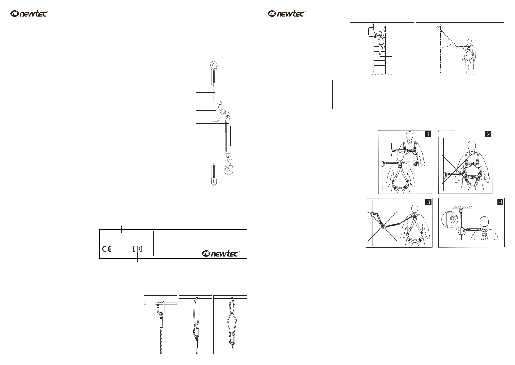
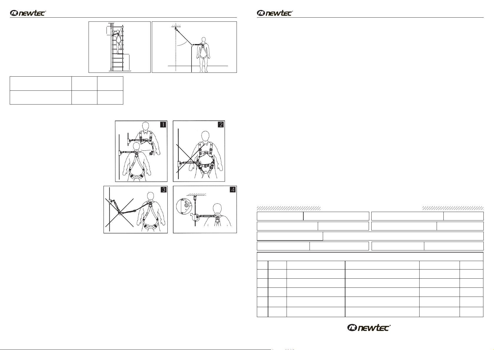
EXIGENCIAS CONCERNIENTES AL
PUESTO DE TRABAJO
Controlar el espacio libre debajo del
puesto de trabajo donde se utilizará el
EPI anticaída, para evitar el impacto con-
tra objetos o superficies subyacentes du-
rante la detención de la caída.
Debajo del usuario, se debe garantizar un
espacio libre de valor variable (diseño A),
según la longitud de la cuerda de trabajo
ubicada arriba del usuario.
Ver tabla:
Se permite una inclinación de 45º de la cuerda de trabajo del plano vertical, en caso de movimiento en dirección horizontal
del trabajador (diseño B).
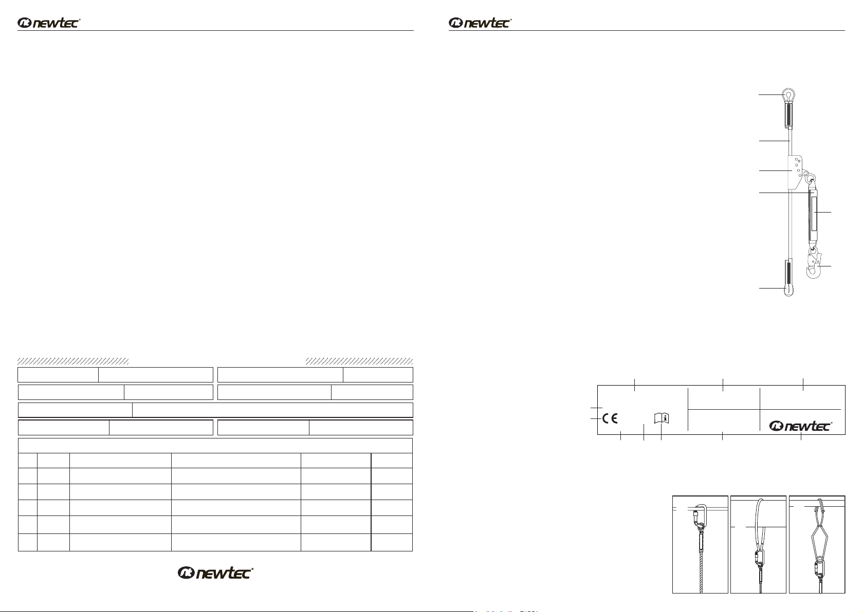
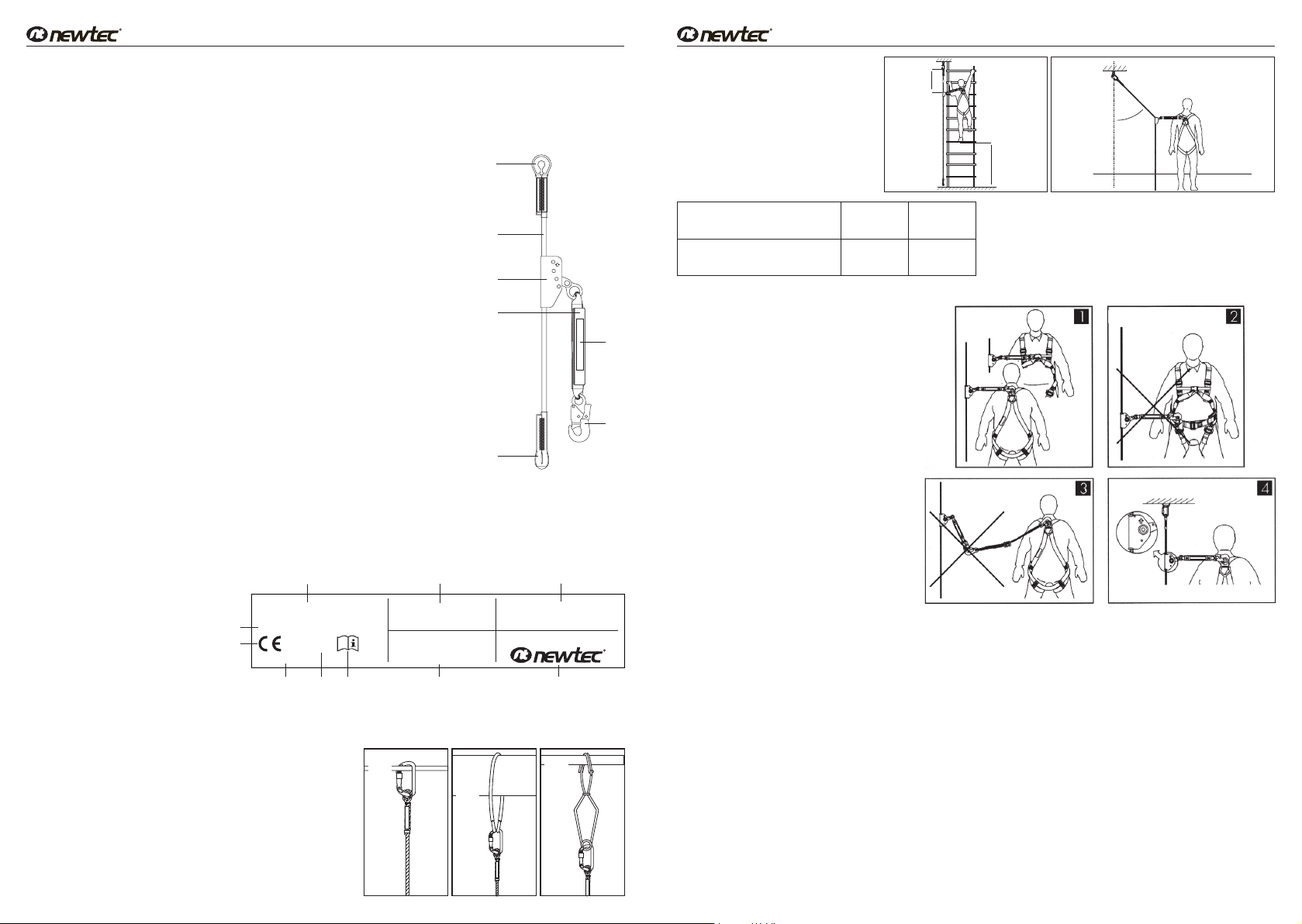
CONEXIÓN AL ARNÉS PARA EL CUERPO
- El dispositivo se debe conectar a las anillas
de enganche esternal o dorsal del arnés para el
cuerpo, a través de un sólo mosquetón (1).
- Está prohibido conectar el dispositivo anticaída
a las anillas del cinturón de posicionamiento (2).
- Está prohibido conectar cualquier elemento en-
tre el mosquetón de conexión y el punto de en-
ganche del arnés (3).
- La flecha que se encuentra en el mecanismo an-
ticaída debe apuntar hacia arriba, en dirección al
punto de anclaje donde está conectada la cuerda
de trabajo (4).
ATENCIÓN: Para evitar que el mosquetón se
abra accidentalmente, controlar siempre que el
cierre de seguridad esté protegido con el meca-
nismo de bloqueo.
NOTAS
Antes de utilizar un sistema anticaída, en el cual
el dispositivo anticaída deslizante es un compo-
nente, se debe comprobar que todos los dispo-
sitivos estén conectados correctamente entre sí,
que funcionen sin interferirse entre sí y que estén
conforme a las normativas vigentes:
- EN 353-1, EN 353-2, EN 354, EN 355, EN 360,
EN 361, EN 362: para los sistemas anticaída.
- EN 795: para los dispositivos de anclaje.
- EN 341: para los dispositivos de descenso.
UTILIZACIÓN
Durante su uso, es necesario proteger todos los elementos del dispositivo del contacto con aceites, solventes, ácidos y bases,
llamas, fragmentos de metal incandescente y objetos de bordes cortantes. Se debe evitar el uso del dispositivo en ambientes
con mucho polvo o aceite.
EXCLUSIÓN DEL SERVICIO
El EPI debe excluirse inmediatamente del uso:
- en caso de cualquier duda sobre el estado y el funcionamiento correcto.
- después de detener una caída.
Después de ser excluido del servicio, el EPI debe enviarse al fabricante o persona autorizada con el fin de llevar a cabo una
revisión detallada y evaluar la posible reparación o destrucción.
REVISIONES PERIÓDICAS
Cada 12 meses de uso, el EPI debe retirarse del servicio y enviarse al fabricante o a la persona autorizada con el fin de llevar
a cabo una revisión periódica. Durante esta revisión se define el período de uso del EPI, hasta la próxima revisión periódica.
Está prohibido utilizar el EPI después de este período sin realizar la próxima revisión. Toda la información sobre la revisión
periódica debe anotarse en la ficha de control del dispositivo.
Las revisiones periódicas y la actualización de la ficha de control son realizadas únicamente por el fabricante o a la persona
autorizada.
PERÍODO DE USO ADMITIDO
La duración prevista del EPI, si se conserva como se especifica en la presente nota informativa y se somete a las revisiones periódi-
cas, es de 5 años desde la fecha del primer uso.
PRINCIPALES REGLAS DE USO DE LOS EQUIPOS DE PROTECCIÓN INDIVIDUAL ANTICAÍDA DE ALTURA
- Los EPI deben ser utilizados sólo por personas entrenadas para su uso.
- Los EPI no pueden ser utilizados por personas cuya condición de salud puede influir en su seguridad durante el uso cotidiano y de
emergencia.
- Se debe preparar un plan para la posible recuperación de emergencia que se debe aplicar en caso de necesidad.
- Está prohibido realizar cualquier modificación en los EPI sin la autorización escrita del fabricante.
- Cualquier reparación de los dispositivos puede ser realizada sólo por el fabricante de los dispositivos o por un representante autori-
zado.
- Los EPI no pueden ser utilizados de forma distinta al uso previsto.
- Los EPI son personales y por lo tanto, deben ser utilizados por una sola persona.
- Antes de usarlos, asegurarse de que todos los elementos del dispositivo estén conectados entre sí de forma correcta.
- Controlar periódicamente las conexiones y el ajuste de los componentes del dispositivo para evitar que se aflojen y/o separen.
- Está prohibido utilizar combinaciones de EPI en los cuales el funcionamiento de cualquier componente del dispositivo impida el funciona-
miento de otro.
- Antes de usar los EPI, se debe realizar una atenta inspección visual para controlar el estado y el funcionamiento.
- Durante la revisión se deben controlar todos los elementos del dispositivo, con especial atención en cualquier daño, desgaste ex-
cesivo, corrosión, abrasión, corte o funcionamiento incorrecto. Prestar especial atención a estos elementos: en el arnés anticaída y
en el cinturón de posicionamiento: a las hebillas, elementos de regulación, puntos de enganche, correas, pasantes, costuras; en los
absorbedores de energía: a los nudos de enganche, cinta/correa; a las costuras, a los conectores; en las cuerdas y en los cables de
trabajo: a la cuerda, nudos, guardacabos, conectores, elementos de ajuste, entrelazados; en los cables de acero de las líneas de
vida: al cable, terminales, grapas, nudos, guardacabos, conectores, elementos de ajuste; en los dispositivos anticaída con enrollador:
al cable/cinta, funcionamiento correcto del enrollador y del dispositivo de bloqueo, carcasa, absorbedor de energía, conectores;
en los dispositivos anticaída deslizantes: al cuerpo del dispositivo, deslizamiento correcto del cable de guía, funcionamiento del
dispositivo de bloqueo, remaches, tornillos, conectores, absorbedor de energía;
en los conectores: al cuerpo de sustentación, remachado, apertura, funcionamiento del dispositivo de bloqueo.
- Si el dispositivo es vendido fuera del país de origen, el proveedor del dispositivo debe incluir las instrucciones de uso, de conserva-
ción y la información sobre las revisiones periódicas y a las reparaciones del dispositivo, en el idioma vigente en el país donde el
dispositivo será utilizado.
- El arnés para el cuerpo conforme a la normativa EN 361 es el único dispositivo admisible para sostener el cuerpo entre los EPI anti-
caída
- Durante el uso de los dispositivos se debe prestar especial atención a los fenómenos peligrosos que influyen en el
funcionamiento de los dispositivos y en la seguridad del usuario, en particular a: la acumulación de nudos y el desplazamiento de las
cuerdas en aristas; caídas pendulares; la conducción de corriente; cualquier daño de tipo corte, abrasión, corrosión; la influencia de
temperaturas extremas;
la influencia negativa de los factores climáticos; la influencia de las sustancias químicas.
- Los EPI deben ser transportados en el embalaje original.
- Los EPI deben limpiarse y desinfectarse de manera tal que no dañen el material (materia prima) con el que está hecho el dispositivo.
Para los materiales de tejido (correas, cuerdas) se debe utilizar detergentes para prendas delicadas. Se pueden lavar a mano o en
lavadora. Se deben secar adecuadamente. Las partes de material plástico deben lavarse sólo con agua. El dispositivo que se moja
durante la limpieza o el uso debe secarse adecuadamente de modo natural, lejos de las fuentes de calor. Las partes y los meca-
nismos de metal (muelles, bisagras, topes de seguridad) pueden lubricarse periódicamente con mucho cuidado para mejorar su
funcionamiento.
- Los EPI deben ser almacenados en su embalaje original, en lugares secos y ventilados, alejados de la luz, de los rayos UV, del polvo,
de objetos cortantes, de temperaturas extremas y de sustancias cáusticas.
- Los EPI deben eliminarse de conformidad con las normativas locales vigentes en materia (vertedero, incinerador).
- El presente EPI se sustituirá en caso de que presente defectos de fabricación.
El establecimiento del usuario tiene la responsabilidad de presentar la “FICHA DE CONTROL” y de introducir los detalles solicitados.
La ficha de control debe completarse antes del primer uso del dispositivo. Toda la información sobre los dispositivos de protección
(nombre, número de serie, fecha de adquisición, fecha del primer uso, nombre del usuario, información sobre las reparaciones y las
revisiones) debe completarse en la “FICHA DE CONTROL”. No está permitido usar los EPI que no tengan la ficha de control completa.
cod. 121055 - mod. FALLSTOP cod. 121055 - mod. FALLSTOP
Tramo de cuerda arriba del
usuario (m) - L
Espacio libre debajo del
trabajador (m) - X
10 20
3.20 4.60
USP BLOCMAX
PN-EN 353-2
Nr kat.: AC 010
Data
produkcji:
DOPUSZCZONE DO STOSOWANIA WY£•CZNIE Z LINAMI
14 mm
Numer
urzπdzenia:
Przed z
astosowaniem
zapoz
naÊ siÍ dok≥adnie
z instrukcjπ uø
ytkowania
POLAND
93-403 £Ûdüul. Starorudzka 9
tel/fax:
(0
42) 683
03
21
(0 42) 683 03 22
USP BLOCMAX
PN-EN 353-2
Nr kat.: AC 010
Data
produkcji:
DOPUSZCZONE DO STOSOWANIA WY£•CZNIE Z LINAMI 14 mm
Numer
urzπdzenia:
Przed zastosowaniem
zapoznaÊ siÍ dok≥adnie
z instrukcjπ uøytkowania
POLAND
93-403 £Ûdü
ul. Starorudzka 9
tel/fax: (0 42) 683 03 21
(0 42) 683 03 22
X
L
A B
Punto
de anclaje
esctructu-
ral 15 kN
Punto de anclaje
esctructural 15 kN
max. 45°
VIETATO!
VIETATO!
PROHIBIDO!
PROHIBIDO!
FICHA DE CONTROL
NOMBRE DEL DISPOSITIVO CÓDIGO
NÚMERO DE SERIE FECHA DE PRODUCCIÓN
NOMBRE DEL USUARIO
FECHA DE COMPRA FECHA DE LA PRIMERA UTILIZACIÓN
INSPECCIONES TÉCNICAS
1
2
3
4
5
FECHA MOTIVO DE LA INSPECCIÓN DAÑOS CONSTATADOS, REVISIONES EFECTUADAS,
OTRAS OBSERVACIONES
FECHA DE LA SIGUIENTE
REVISIÓN PERIÓDICA
FIRMA DEL
RESPONSABLE
Para más informaciones dirigirse a:
Marca Comunitaria Depositada n. 001240407 En UAMI - Alicante - Spagna