Nexmosphere X-EYE User manual

1. General
Nexmosphere's X-Eye Motion sensor detects the amount of motion within it's detection area. This document provides
explanation of the available functionalities and instructions on how to install and integrate the sensor into your digital signage
installation.
The information in this document is created for users who are familiar with the Nexmosphere API and are able to control a
basic setup with a Nexmosphere API controller. If this is not the case yet, please read the general documentation on the
Nexmosphere serial API rst.
Nexmosphere
Le Havre 136
5627 SW Eindhoven • The Netherlands
T+31 40 240 7070
Esupport@nexmosphere.com
PRODUCT MANUAL
© 2020 Nexmosphere. All rights reserved. v1.0 / 12-20
All content contained herein is subject to change without prior notice
1
Table of content
1. General 1
2. Product overview 1
3. Functionality and API commands 2
3.1 Motion detection 2
4. Installation requirements and guidelines 3
4.1 Connection Diagrams 3
4.2 Hardware integration guidelines 3
5. Settings 5
6. Quick test 6
2. Product overview
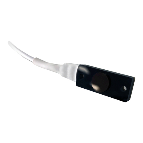
The X-Eye Motion sensor is available in 1 model: XY-320.
The X-Eye Motion sensor continuously sends out
electromagnetic waves. These waves reect on objects
and persons and are then received back by the sensor.
Utilizing the doppler-eect, the sensor can calculate the
amount of motion within its detection eld.
XY-320

© 2020 Nexmosphere. All rights reserved. v1.0 / 12-20
All content contained herein is subject to change without prior notice
Nexmosphere
Le Havre 136
5627 SW Eindhoven • The Netherlands
T+31 40 240 7070
Esupport@nexmosphere.com
The X-Eye Motion sensors provides the following functionalities:
1. Detect motion - detect motion within its detection eld
This information is translated into an API message which has
the following format:
X001A[X]
When the sensors detects motion - typically when a
person moves within its detection eld - the sensor will
trigger an API command indicating the amount of motion
which was detected. When applying these commands,
please consider the following:
• The higher the number, the higher the amount of
motion detected. When no motion is detected, the
output will be 0.
• The amount of motion is a determined by the size,
velocity and direction of the object or person which
is moving. Please see section 4, page 3 for more info.
• The detection area/range of the motion sensor can be
adjusted. Please see section 5 "Settings", page 5.
The following section will cover this functionality in detail. Please note that for each API example in this document,
X-talk interface address 001 is used (X001). When the sensor is connected to another X-talk channel, replace the
"001" with the applicable X-talk address.
Example commands
Motion detected, amount of motion is "4"
Motion detected, amount of motion is "12"
Motion detected, amount of motion is "23"
No motion detected (amount of motion is "0")
X001A[4]
X001A[12]
X001A[23]
X001A[0]
transceiving side
X-Eye
X= amount of motion value between 0-50
When integrating an X-Eye Motion sensor into your digital signage installation, several installation requirements and guidelines
need to be taken into account in order for the sensor to perform optimal and operate stable.
The X-Eye Motion sensor can be connected to any X-talk interface and is therefore compatible with all Xperience controllers.
Make sure the X-Eye Motion sensor is connected to the X-talk interface before powering the Xperience controller. Otherwise,
the X-Eye Motion sensor will not be recognized by the Xperience controller and no sensor output will be provided.
XN
transceiving side
X-Eye
DC Power supply
XC
transceiving side
X-Eye
Example connection to XC Controller Example connection to XN Controller
2

© 2020 Nexmosphere. All rights reserved. v1.0 / 12-20
All content contained herein is subject to change without prior notice
Nexmosphere
Le Havre 136
5627 SW Eindhoven • The Netherlands
T+31 40 240 7070
Esupport@nexmosphere.com
3
Top panel
The X-Eye Motion sensor can be installed behind any non-metal surface, creating a completely invisible solution.
Although there is no maximum recommended thickness, please note that the type and thickness of the material behind
which the sensor is placed does inuence the output number which indicates the amount of motion.
For example: when placing the sensor behind a brick wall, the output number in the API message indicating the amount of
motion will be lower than when placed behind a 3mm acrylic panel.
Sensor output
The amount of motion which the sensor detects is determined by the size, velocity and direction of the object or person
which is moving within the sensor's detection eld:
• The larger the size, the higher the amount of motion
• The higher the velocity, the higher the amount of motion.
• The more perpendicular the direction of the motion in relation to the sensor, the higher the amount of motion
Sensor placement
The sensor output is inuenced by the direction of the
motion in relation the sensor. Therefore we recommend to
place the sensor in such a way that people typically move
towards or away from the sensor.
When the sensor is placed in such a way that people typi-
cally move in parallel with the sensor (for example in a ceil-
ing), the output of the sensor will be signicantly lower.
Avoid overlap detection areas
When installing multiple X-Eye Motion sensors, please
make sure to avoid any overlap of detection areas. This will
prevent cross-interference and unstable behaviour.
Transceiving side
The X-Eye Motion sensor has a transceiving side and non-transceiving side. This is indicated on the sensor. Make sure the
sensor is placed in such a way that the transceiving side is faced towards the direction in which motion needs to be detected.
Shape and size detection area
The shape of the detection area is indicated in the visuals
on the right. The size of the detection area can be adjusted.
Please see section 5 "Settings", page 5.
0
30
60
90
120
150
180180
210
240
270
300
330
0
30
60
90
120
150210
240
270
300
330

X is a value between 1-250 and its default value is 25. The
measurement duration determines how long the sensor
measures motion before an API output trigger is provided.
The sensors does a cumulative measurement of the
motion detected. Therefore, increasing the measurement
duration will make the output from the sensor less
responsive, but will also increases the resolution of the
output.
For example: when a person is performing the same
continuous movement, the sensor's output will be higher
when the measurement duration is increased, as the
duration during which the sensor can sense motion and
"add" to the cumulative measurement is longer
Vice versa, decreasing X will result into a faster response
of the sensor when movement is detected, but also
decreases the resolution.
X is a value between 1-125 and its default value is 12. It
has an inversed correlation with the size of the detection
area. So the lower the X value, the larger the detection area
and vice versa.
Indication of detection area (indicated as the range in the
perpendicular direction of the sensor):
1 = +/- 10 meter range
12 = +/- 3.5 meter range (default)
25 = +/- 2 meter range
125 = +/- 1 meter range
© 2020 Nexmosphere. All rights reserved. v1.0 / 12-20
All content contained herein is subject to change without prior notice
Nexmosphere
Le Havre 136
5627 SW Eindhoven • The Netherlands
T+31 40 240 7070
Esupport@nexmosphere.com
The X-Eye Motion sensor has multiple settings which determine the behaviour and output of the sensor. The settings can
be adjusted by sending X-talk setting commands via the API. After a power cycle, the settings always return back to default.
X001S[3:X]
X001S[5:X]
Setting 3: Measurement duration
Set measurement duration
Setting 5: Size/range of detection area
Set size detection area
X001S[1:1]
X001S[1:2]
X001S[1:3]
X001S[1:4]
Setting 1: Status LED behaviour
1. LED on
2. LED o
3. LED on, blink at trigger (default)
4. LED o, blink at trigger
4

6. Quick test
In order to test if the X-Eye Motion sensor is installed correctly, please follow the test procedure below:
© 2020 Nexmosphere. All rights reserved. v1.0 / 12-20
All content contained herein is subject to change without prior notice
Nexmosphere
Le Havre 136
5627 SW Eindhoven • The Netherlands
T+31 40 240 7070
Esupport@nexmosphere.com
5
Step 1 - Setup
First, connect the X-Eye Motion sensor to an
Xperience controller. Secondly, power the Xperience
controller.
The green status LED of the X-Eye Motion sensor
should go on. The status LED of the controller will
start to blink and once power-up is completed will be
lit continuously
Step 2 - Test detection
Move in perpendicular direction towards or away
from the sensor.
Both the green status LED of the sensor and the status
LED of the controller should blink once.
For a full test we recommend to connect the setup to
a mediaplayer or PC and test all API commands listed
in this document (see section 3, page 2). For more
information on how to setup a test for your controller,
please see the Quick Start Guide of the Xperience
controller you are using. These are available on
nexmosphere.com/support-documentation
Please contact support@nexmosphere.com for any
support questions you may have.
In case any of the 2 steps above do not provide
the expected result, please check the installation
guidelines in this document.
XN
Connect to powered
USB port
transceiving side
X-Eye
XN
LED BLINK
transceiving side
X-Eye
sensor
Table of contents
Other Nexmosphere Accessories manuals
Nexmosphere
Nexmosphere X-EYE XY-510 User manual
Nexmosphere
Nexmosphere XF-P3W User manual
Nexmosphere
Nexmosphere X-Dot Motion Series User manual

Nexmosphere
Nexmosphere XD Series User manual
Nexmosphere
Nexmosphere XZ Series User manual

Nexmosphere
Nexmosphere XV User manual
Nexmosphere
Nexmosphere XS Series User manual
Nexmosphere
Nexmosphere X-EYE XY-116 User manual
Nexmosphere
Nexmosphere XT-EF Series User manual

Nexmosphere
Nexmosphere XZ Series User manual
