Nexmosphere XT-EF Series User manual

1. General
The Nexmosphere XT-EF Series oers E-eld sensors in various sizes which are able to detect touchless input from the
user. This document provides explanation of the available functionalities and instructions on how to install and integrate the
sensor into your digital signage installation.
The information in this document is created for users who are familiar with the Nexmosphere API and are able to control a
basic setup with a Nexmosphere API controller. If this is not the case yet, please read the general documentation on the
Nexmosphere serial API rst.
2. Product overview
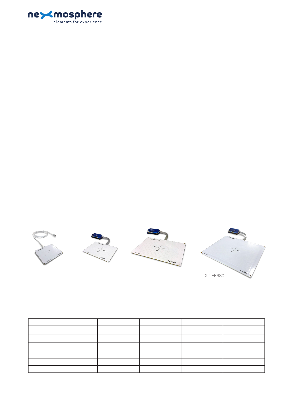
The XT-EF Series consists out of 4 products:
XT-EF30 XT-EF630 XT-EF650 XT-EF680
All XT-EF sensors feature AirButton detection which will trigger whenever a person's hand either enters or leaves the sensor's
detection eld. The XT-EF630, XT-EF650 and XT-EF680 also oer AirGesture detection which includes detecting AirSwipes
and AirWheels. The detection range of the sensors varies with the size.
Nexmosphere
Le Havre 136
5627 SW Eindhoven • The Netherlands
T +31 40 240 7070
E support@nexmosphere.com
PRODUCT MANUAL
© 2020 Nexmosphere. All rights reserved. v1.0 / 11-20
All content contained herein is subject to change without prior notice
1
Table of content
1. General 1
2. Product overview 1
3. Functionality and API commands 2
3.1 AirButton 2
3.2 AirSwipe 3
3.3 AirWheel 4
4. Installation requirements and guidelines 5
4.1 Electrical installation requirements 5
4.2 Connection Diagrams 5
4.3 Hardware integration guidelines 6
5. Settings 9
6. Quick test 10
XT-EF30 XT-EF630 XT-EF650 XT-EF680
AirButton detection
✔ ✔ ✔ ✔
AirGesture detection
✖✔ ✔ ✔
Integrated sensor driver
✔✖ ✖ ✖
Detection range AirButton up to130mm up to 130mm up to 150mm up to170mm
Detection range AirGesture
✖
up to 80mm up to 100mm up to 140mm
Sensor dimensions (L x W) 110x90mm 110x90mm 160x110mm 200x160mm

© 2020 Nexmosphere. All rights reserved. v1.0 / 11-20
All content contained herein is subject to change without prior notice
Nexmosphere
Le Havre 136
5627 SW Eindhoven • The Netherlands
T +31 40 240 7070
E support@nexmosphere.com
2
The XT-EF Series sensors provide the following functionalities:
1. AirButton - detects when a hand enters or leaves the sensor's detection eld
2. AirSwipe - detects swipes to the left, right, up and down
3. AirWheel - detects circular movements clockwise and anti-clockwise
The following sections will cover each of these functionalities in detail. Please note that for each API example in this
document, X-talk interface address 001 is used (X001). When the sensor is connected to another X-talk channel,
replace the "001" with the applicable X-talk address.
channel.
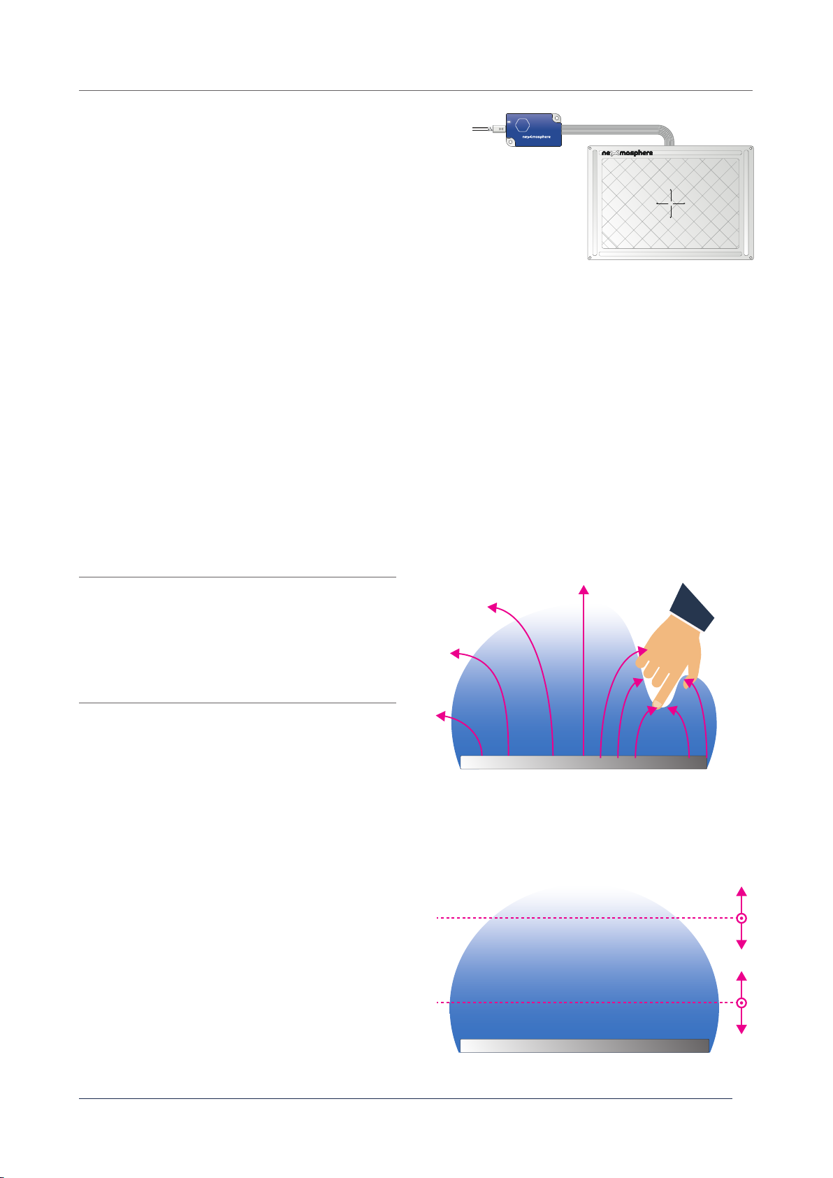
X001B[Bs=FAR] AirButton status FAR
X001B[Bs=NEAR] AirButton status NEAR
X001B[Bs=IDLE] AirButton status IDLE /
hand left detection eld
When implementing AirButton triggers, consider the
following:
• The sensitivity/range of the FAR and NEAR detection
level can be adjusted. Please see section 3.4
"Settings", page 9.
• The maximum range for AirButton detection is
dierent for each XT-EF sensor model. Please see the
overview on page 1 for more info.
• AirButton detection can be disabled. Please see
section 3.4 "Settings", page 9.
• When an AirButton (far or near) is detected, the sensor
checks for a short period of time if an AirGesture is
detected as well. This avoids that both an AirButton
and AirGesture API-command is send during an
AirGesture event. The duration for which the system
checks for AirGestures - and the AirButton trigger
is delayed - is adjustable. Please see section 3.4
"Settings", page 9.
EF sensor
EF sensor
AirButton FAR
AirButton NEAR
AirButton IDLE
adjustableadjustable
The XT-EF Series sensors consist out of 2 main parts: the AirGesture
Driver and the Electrode. The sensor's electrode creates an electrical
eld which denes the detection area of the sensor. The driver
analyses the signals coming from the electrode and connects to
the Xperience controller via X-talk. The XT-EF6xx sensors all have a
separate driver. The EF30 sensor has an integrated on-board driver.
The XT-EF Series sensors can detect when a hand is placed above the sensor (both far and near) as well as when it leaves
the detection eld. The API output for these triggers is as follows:
XT
XT-EF650transceiving side
LEFT
UP
DOWN
RIGHT
AirGesture Driver
Electrode
(detection eld)

© 2020 Nexmosphere. All rights reserved. v1.0 / 11-20
All content contained herein is subject to change without prior notice
Nexmosphere
Le Havre 136
5627 SW Eindhoven • The Netherlands
T +31 40 240 7070
E support@nexmosphere.com
3
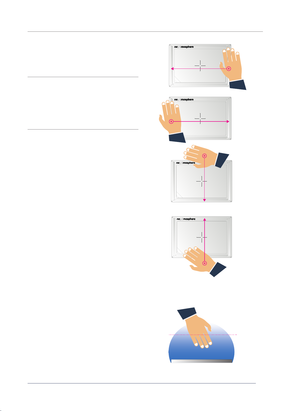
The XT-EF Series can detect swipe gestures within the
detection eld of the sensor.
The API output for these triggers is as follows:
X001B[Sd=LEFT] AirSwipe direction LEFT
X001B[Sd=RIGHT] AirSwipe direction RIGHT
X001B[Sd=DOWN] AirSwipe direction DOWN
X001B[Sd=UP] AirSwipe direction UP
When implementing AirSwipe triggers, consider the
following:
• The sensitivity/range of the AirSwipe detection level is
xed and can't be adjusted.
• The maximum range for AirSwipe detection is
dierent for each XT-EF sensor model. Please see the
overview on page 1 for more info.
• AirSwipe detection can be disabled. Please see
section 3.4 "Settings", page 9.
• In order for a swipe gesture to be detected, the hand
movement needs to cover a least 70% of the sensor
's length (left-right) or width (up-down).
• When an AirButton command is send while executing
an AirSwipe, consider increasing the AirButton
delay setting. Fore more info please see section 3.4
"Settings", page 9.
• Make sure the sensor is positioned in such a way that
the swipe gestures can be performed in a natural way.
Fore more info please see section 4.3 page 8.
XT-EF650transceiving side
LEFT
UP
DOWN
RIGHT
XT-EF650transceiving side
LEFT
UP
DOWN
RIGHT
XT-EF650transceiving side
LEFT
UP
DOWN
RIGHT
XT-EF650transceiving side
LEFT
UP
DOWN
RIGHT
EF sensor
xed
Swipe gesture
LEFT
Swipe gesture
RIGHT
Swipe gesture
UP
Swipe gesture
DOWN
Sideview illustration of
a swipe gesture with
indication of the (xed)
detection range

© 2020 Nexmosphere. All rights reserved. v1.0 / 11-20
All content contained herein is subject to change without prior notice
Nexmosphere
Le Havre 136
5627 SW Eindhoven • The Netherlands
T +31 40 240 7070
E support@nexmosphere.com
4
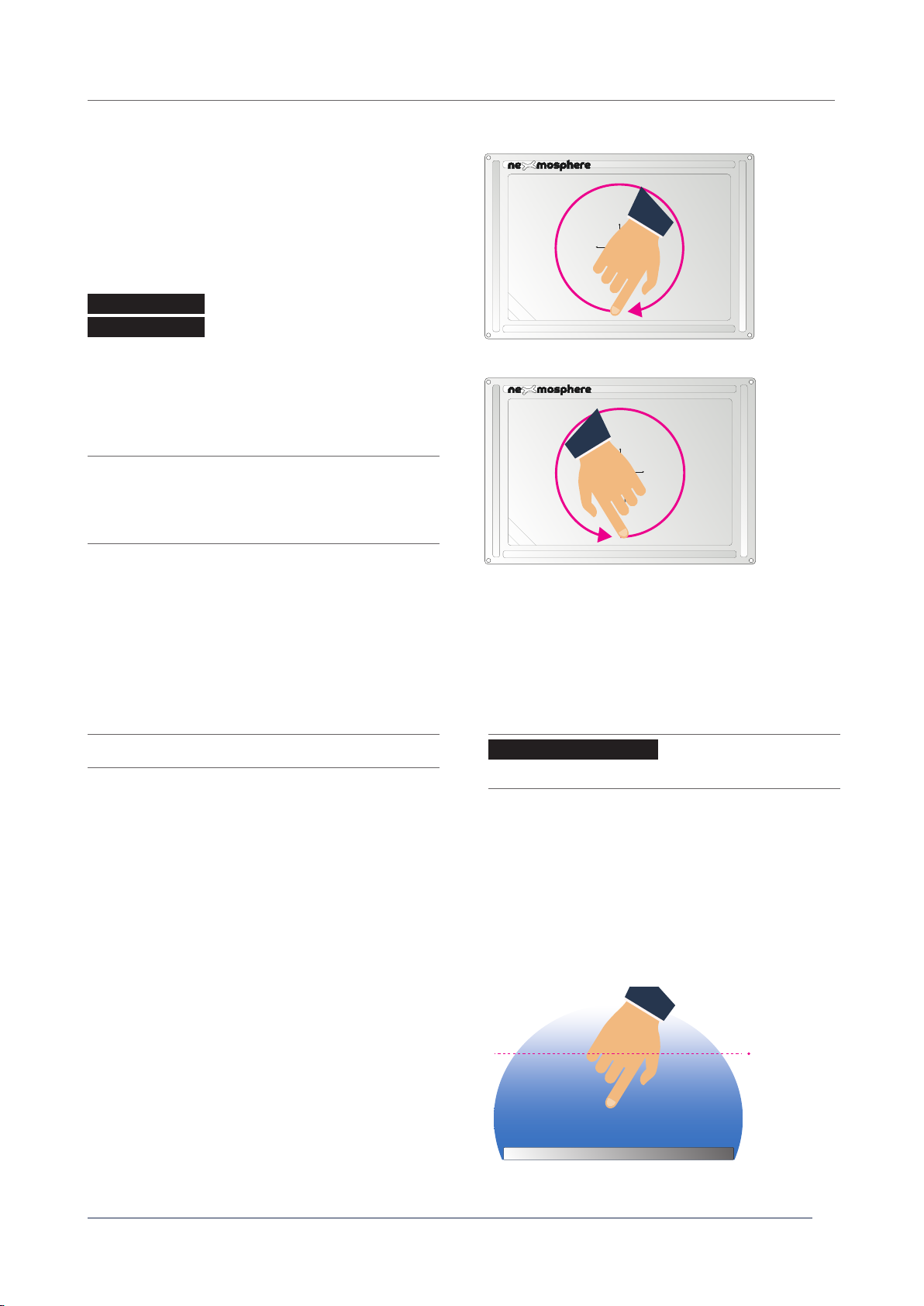
The XT-EF Series can detect circular gestures ("AirWheels")
within the detection eld of the sensor. The output for
AirWheel detection can be set to two dierent modes:
"incremental" and "absolute value". Per default, AirWheel
detection is disabled. It can be activated by sending one of
the following settings:
Enable AirWheel incremental mode
Enable AirWheel absolute value mode
Incremental mode
When the mode is set to incremental, an API output is
send each time an AirWheel is detected. The API output
for these triggers is as follows:
X001B[Wd=CW] AirWheel direction CLOCKWISE
X001B[Wd=CCW] AirWheel direction COUNTER-
CLOCKWISE
Absolute value mode
When the mode is set to absolute value, the sensor
keeps track of a value between 1-100 and increases this
value when the detected AirWheel direction is clockwise
and decreases this value when the detected direction is
counter clockwise. The API output for AirWheel detection
in "absolute value" mode is as follows:
X001B[Wv=XXX] AirWheel value (XXX = 001-100)
When implementing AirWheel triggers, consider the
following:
• The amount of API triggers per full rotation can be
adjusted. Please see section 3.4 "Settings", page 9.
• When the absolute value has reached 100 (max),
clockwise rotations will not result in new API triggers.
The same goes for value 1 (min) and counter clockwise
rotations.
• The sensitivity/range of the AirWheel detection level
is xed and can't be adjusted.
• The maximum range for AirWheel detection is
dierent for each XT-EF sensor model. Please see the
overview on page 1 for more info.
• When an AirButton command is send while executing
an AirWheel, consider increasing the AirButton
delay setting. For more info please see section 3.4
"Settings", page 9.
Air Wheel
Clockwise
Air Wheel
Counter-
clockwise
XT-EF650transceiving side
LEFT
UP
DOWN
RIGHT
XT-EF650transceiving side
LEFT
UP
DOWN
RIGHT
EF sensor
xed
Sideview illustration of
an AirWheel gesture
with indication of the
(xed) detection range
X001S[7:2]
X001S[7:3]
X001B[SETW=XXX]
The airwheel value can be (re)set to a value between 001-
100 by sending the following API command:
For example, to set the AirWheel value to 075, send:
X001B[SETW=075]
Set AirWheel value
(XXX= 001 - 100)

© 2020 Nexmosphere. All rights reserved. v1.0 / 11-20
All content contained herein is subject to change without prior notice
Nexmosphere
Le Havre 136
5627 SW Eindhoven • The Netherlands
T +31 40 240 7070
E support@nexmosphere.com
When integrating an XT-EF Series sensor into your digital signage installation, several installation requirements and guidelines
need to be taken into account in order for the sensor to perform optimal and operate stable.
Grounding
The XT-EF Series sensors transceives an electrical eld and measures changes within that eld. Based on these changes, it
can detect AirButton and AirGesture input. In order for the electrical eld to remain stable, the sensor needs to be grounded.
This can be achieved via two main methods:
• Use a grounded power supply to power the Xperience controller (to which the XT-EF sensor is connected. An overview
of the connection options is provided in section 4.2
• Connect the Xperience controller (to which the XT-EF sensor is connected), to a mediaplayer or PC which is grounded.
Please note that most mediaplayers are not grounded.
Avoid proximity of oating ground planes
When the sensor is placed in close proximity to large oating ground planes, this can cause interference of the electrical
eld of the XT-EF sensor which can result into unstable behaviour. A typical example would be a large monitor which is not
grounded. Please note that when the Xperience controller is powered with a grounded power supply, this will also ground the
connected mediaplayer/PC, which subsequently will also ground the connected monitor.
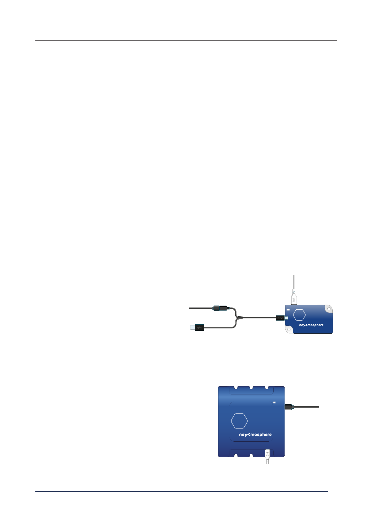
XN Controllers (XN-135, XN-165, XN-185, XN-180)
All XN controllers are powered via USB. As USB power
supplies are typically not grounded, a USB/DC split
cable is needed to which a grounded power supply can
be connected.
There are multiple options for grounding the dierent Xperience controllers using a grounded power supply:
XC Controllers (XC-700, XC-800 and XC-900 Series)
All XC controllers are powered via 12 or 24V DC input
to which a grounded power supply can be connected.
24V/1.67A grounded power supply EU: PS-2416EU
24V/1.67A grounded power supply US: PS-2416US
24V/3.75A grounded power supply EU: PS-2438EU
24V/3.75A grounded power supply US: PS-2438US
5
Grounded DC
Power supply
XC
X-talk cable to
XT-EF sensor
XN
5V grounded
power supply
CA-UD5B
split cable USB/DC
X-talk cable to
XT-EF sensor

© 2020 Nexmosphere. All rights reserved. v1.0 / 11-20
All content contained herein is subject to change without prior notice
Nexmosphere
Le Havre 136
5627 SW Eindhoven • The Netherlands
T +31 40 240 7070
E support@nexmosphere.com
6
XM Controllers (XM-350 and XM-370)
All XM controllers are powered via 5V DC input to which
a grounded power supply can be connected.
Currently, Nexmosphere does not have grounded 5V
power supplies in it's product portfolio.
EM Modules (EM-2, EM-5 and EM-6)
Some EM modules have a DC power input to which a
grounded power supply can be connected.
EM-2 and EM-5
Currently, Nexmosphere does not have grounded 12V
power supplies in it's product portfolio.
EM-6
24V/1.67A grounded power supply EU: PS-2416EU
24V/1.67A grounded power supply US: PS-2416US
24V/3.75A grounded power supply EU: PS-2438EU
24V/3.75A grounded power supply US: PS-2438US
X-talk cable to
XT-EF sensor
5V grounded
power supply
X-talk cable to
XT-EF sensor
Grounded DC
Power supply
Top panel material
The XT-EF Series sensor can be installed behind any non-metal top panel, creating a completely invisible solution. The
maximum recommended thickness for the XT-EF30, XT-EF630 and XT-EF650 is 22mm for acrylic or glass, and 18mm for
wood. For these models, the material and thickness of the top panel will only have a minor aect (if any) on the detection
range and the performance in general.
The XT-EF680 has a dierent technical design to create a large sensor surface and high detection range. Therefore the
XT-EF680 is more sensitive to the material and thickness of the applied top panel. There are 7 calibration prole settings
available for the XT-EF680 to optimize the performance for a specic type of top panel (see section 3.4, page 5). This enables
the sensor to be placed behind a thick surface such as 36mm of wood or 100mm of brick. Please note that the calibration
proles for these thick surfaces are tuned to a situation in which the sensor is only attached to the surface and has free space
on the back. For example during a test situation, when placing the sensor on a table and then placing a 36mm wooden test
panel on top, the sensor might not perform optimal as the back of the sensor is not free, but placed on a table top.
EF sensor
Top panel

Clearance from metal objects/surfaces
Metal objects or surfaces parallel to the XT-EF sensor
or to the side can cause interference of the electrical
eld which results into unstable behaviour. Please
take the clearances indicated in the table below into
account.
Clearance between XT-EF sensors side-by-side
When using multiple XT-EF sensors side-by-side the
electrical elds of the sensors will interfere with each
other when placing the sensors too close next to each
other. Therefore please make sure that the minimum
spacing indicated in the table below are taken into
account.
Double glazing
The XT-EF sensors do not work behind most types of double glazing used to insulate indoor environments from outdoor
environments (e.g. double glazing used in windows or doors at store fronts). The reason for this is that most modern
types of double glass have a very thin invisible metal foil inside to reect heat. The metal foil blocks the electrical eld
of the sensor, causing the sensor not to detect any AirButton or AirGestures. Next to that, some types of gas applied to
insulate the two glass panels may have a negative eect on the detection range.
Please note that the XT-EF sensor does work behind almost all other common types of glass, whether it is with 1 glass
panel or multiple.
© 2020 Nexmosphere. All rights reserved. v1.0 / 11-20
All content contained herein is subject to change without prior notice
Nexmosphere
Le Havre 136
5627 SW Eindhoven • The Netherlands
T +31 40 240 7070
E support@nexmosphere.com
7
parallel
clearance
side
clearance
XT-EF30 80mm 40mm
XT-EF630 80mm 40mm
XT-EF650 100mm 50mm
XT-EF680 120mm 60mm
recommended clearance
XT-EF30 60mm
XT-EF630 60mm
XT-EF650 80mm
XT-EF680 100mm
EF sensor
side
clearance
side
clearance
parallel
clearance
metal
metal
metal
XT-EF650transceiving side
LEFT
UP
DOWN
RIGHT
XT-EF650transceiving side
LEFT
UP
DOWN
RIGHT
XT-EF650transceiving side
LEFT
UP
DOWN
RIGHT
XT-EF650transceiving side
LEFT
UP
DOWN
RIGHT
clearance
clearance
clearance clearance
Transceiving side
The XT-EF sensor electrode has a transceiving side
and non-transceiving side. This is indicated on the sen-
sor at the bottom left. Make sure the sensor is placed in
such a way that the transceiving side is facing the user.
When using a top panel, the transceiving side should
be attached to the panel.
XT-EF650transceiving side
transceiving side
LEFT
UP
DOWN
RIGHT

Positioning of sensor
The positioning of the sensor (height, angle and orientation) has a signicant impact on how a person executes the
AirGestures and -as a results- how well the XT-EF sensor is able to detect those gestures. Although we always recommend
to test what works best for your application, below are some general guidelines as reference.
Horizontal Vertical Angled
© 2020 Nexmosphere. All rights reserved. v1.0 / 11-20
All content contained herein is subject to change without prior notice
Nexmosphere
Le Havre 136
5627 SW Eindhoven • The Netherlands
T +31 40 240 7070
E support@nexmosphere.com
8
recommended positioning recommended height
AirButton Any
(horizontal, vertical or angled)
horizontal or angled - below shoulder height
vertical - shoulder height
AirSwipe
left/right
Any
(horizontal, vertical or angled)
horizontal or angled - below shoulder height
vertical - any height
AirSwipe
up/down Vertical or Angled vertical - shoulder height
angled - below shoulder height
AirWheel Any
(horizontal, vertical or angled)
horizontal or angled - below shoulder height
Vertical - shoulder height
EF sensor
EF sensor
EF sensor
Recalibration
The XT-EF sensor recalibrates each time an AirGesture is detected. When changing top panels or replacing the sensor,
please perform a swipe gesture to activate the recalibration. The recalibration process lasts less than a second and does
not interfere with normal operation.

© 2020 Nexmosphere. All rights reserved. v1.0 / 11-20
All content contained herein is subject to change without prior notice
Nexmosphere
Le Havre 136
5627 SW Eindhoven • The Netherlands
T +31 40 240 7070
E support@nexmosphere.com
9
The XT-EF Series has multiple settings which determine the behaviour and output of the sensor. The settings can be adjusted
by sending X-talk setting commands via the API.
X001S[1:1]
X001S[5:1]
X001S[6:1]
X001S[7:1]
X001S[11:X]
X001S[12:X]
X001S[13:X]
X001S[1:2]
X001S[5:2]
X001S[6:2]
X001S[7:2]
X001S[1:3]
X001S[1:4]
Setting 1: Status LED behaviour
1. LED on
2. LED o
3. LED on, blink at trigger (def)
4. LED o, blink at trigger
Setting 5: (De)activate AirButton
1. Deactivate AirButton detection
2. Activate AirButton detection (def)
Setting 6: (De)activate AirSwipe
1. Deactivate AirSwipe detection
2. Activate AirSwipe detection (def)
Setting 7: (De)activate AirWheel
1. Deactivate AirWheel detection (def)
2. Activate AirWheel detection
Setting 11: Detection range for AirButton FAR
Setting 12: Detection range for AirButton NEAR
Setting 13: Hysteresis for AirButton FAR
Set AirButton FAR detection range
Set AirButton NEAR detection range
Set AirButton FAR hysteresis
X is a value between 2-100 and it's default value is 10. It
has an inversed correlation with the detection range for
AirButton "FAR" detection. So the lower the X value, the
higher the detection distance and vice versa.
When activated, the red status LED on the XT-EF driver will
blink when a high level of interference (e.g. large electronic
equipment with oating ground planes) is detected.
For more info on this setting please see section 4.3 page 7
X is a value between 1-100 and it's default value is 20 (for
XT-EF680 default is 15). It has an inversed correlation with
the detection range for AirButton "NEAR" detection. So the
lower the X value, the higher the detection distance and
vice versa. Please note that the 1-100 range for AirButton
NEAR has a dierent correlation to the absolute detection
range then the 1-100 range for AirButton Far.
X is a value between 1-50 and it's default value is 10. It
determines how far the hand needs to be placed above the
AirButton FAR threshold in order for the sensor to detect
an AirButton IDLE state. It has an inversed correlation:
decreasing X will increase the responsiveness for a switch
from FAR to IDLE, but can also make the sensor more
twitchy. Vice versa, increasing X will make the switch
from FAR to IDLE less responsive, but can also make the
sensor's FAR / IDLE detection more stable.
X001S[14:X]
Setting 14: AirButton trigger delay
Set AirButton FAR hysteresis
X is a value between 1-200 and it's default value is 40.
When an AirButton is detected, the sensor checks for a
short period of time if an AirGesture is detected as well.
This avoids that both an AirButton and AirGesture API
command are send during an AirGesture event. The
duration for which the system checks for AirGestures (and
the AirButton trigger is delayed) is determined by the X
value. The delay time is X * 5mS. For example if X is 40, the
delay time is 40*5mS = 200mS.
X001S[21:1]
X001S[27:1]
X001S[28:1]
X001S[21:2]
X001S[27:2]
X001S[28:2]
X001S[28:3]
X001S[28:4]
X001S[28:6]
X001S[28:5]
X001S[28:7]
X001S[21:3]
X001S[21:4]
1. Trigger 8x per rotation
2. Trigger 4x per rotation
3. Trigger 2x per rotation (def)
4. Trigger 1x per rotation
1. Deactivate indication (def)
2. Activate indication
1. No top panel - for testing
2. Acrylic 3mm (def)
3. Acrylic 6mm
4. Acrylic 10mm
5. Wood 18mm
6. Wood 36mm
7. Brick/stone100mm
Setting 21: Trigger resolution for AirWheel detection
Setting 27: (De)activate interference indication red LED
Setting 28: Calibration prole (XT-EF680 only)
EF sensor
100
100
2
AirButton FAR
AirButton NEAR
setting 11
1
setting 12
50
1
setting 13
AirButton FAR hysteresis

6. Quick test
In order to test if the XT-EF sensor is installed correctly, please follow the test procedure below:
© 2020 Nexmosphere. All rights reserved. v1.0 / 11-20
All content contained herein is subject to change without prior notice
Nexmosphere
Le Havre 136
5627 SW Eindhoven • The Netherlands
T +31 40 240 7070
E support@nexmosphere.com
10
Step 1 - Setup
First, connect the XT-EF sensor to an Xperience
controller. Secondly, power the Xperience controller
by plugging in the grounded power supply (see
section 4.2, page 6 for more info)
The white status LED of the XT-EF driver should go on.
The status LED of the controller will start to blink and
once power-up is completed will be lit continuously
Step 2 - Test AirButton trigger
Place your hand above the XT-EF sensor electrode.
Make sure your hand is placed well within the range
of the sensor.
Both the white status LED of the XT-EF driver and the
status LED of the controller should blink once.
Step 3 - Test AirSwipe trigger
Swipe your hand above the XT-EF sensor electrode
to the left or right. Make sure your hand is placed
well within the range of the sensor.
Both the white status LED of the XT-EF driver and the
status LED of the controller should blink once.
For a full test we recommend to connect the setup to
a mediaplayer or PC and test all API commands listed
in this document (see section 3, page 2-5). For more
information on how to setup a test for your controller,
please see the Quick Start Guide of the Xperience
controller you are using. These are available on
nexmosphere.com/support-documentation
Please contact support@nexmosphere.com for any
support questions you may have.
In case any of the 3 steps above does not provide the
expected result, please check the installation
guidelines in this document.
Grounded DC
Power supply
Xperience controller
X-talk cable
XT-EF Driver
XT-EF Electrode
XC
XT
XT-EF650transceiving side
LEFT
UP
DOWN
RIGHT
XC
XT
XT-EF650transceiving side
LEFT
UP
DOWN
RIGHT
LED BLINK LED BLINK
Grounded DC
Power supply
Xperience controller
X-talk cable
XT-EF Driver
XT-EF Electrode
XC
XT
XT-EF650transceiving side
LEFT
UP
DOWN
RIGHT
LED BLINK LED BLINK
Grounded DC
Power supply
Xperience controller
X-talk cable
XT-EF Driver
XT-EF Electrode
This manual suits for next models
4
Table of contents
Other Nexmosphere Accessories manuals

Nexmosphere
Nexmosphere XF-P3W User manual

Nexmosphere
Nexmosphere XZ Series User manual

Nexmosphere
Nexmosphere X-EYE User manual

Nexmosphere
Nexmosphere XV User manual

Nexmosphere
Nexmosphere X-EYE XY-116 User manual

Nexmosphere
Nexmosphere XZ Series User manual

Nexmosphere
Nexmosphere XZ-A40 User manual

Nexmosphere
Nexmosphere XD Series User manual

Nexmosphere
Nexmosphere X-Dot Motion Series User manual

Nexmosphere
Nexmosphere XE Series User manual