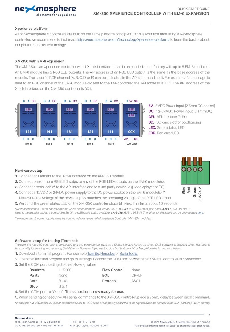
Software setup for testing (Terminal)
Typically, the XM-350 controller is connected to a 3rd party device, such as a Digital Signage Player, on which CMS software is installed which has built-in
functionality for sending and receiving Serial Events. However, if you want to do a rst test on a PC or Mac, follow the instructions below:
1. Download a terminal program. For example Termite, Hercules or SerialTools.
2. Open the Terminal program and go to settings. Choose the COM port to which the XM-350 controller is connected*.
3. Set the COM port settings to the following values
Baudrate 115200 Flow Control None
Parity None EOL CR+LF
Data Bits 8 Protocol ASCII
Stop Bits 1
4. Set the COM port to “Open”. The controller is now ready for use.
5. When sending consecutive API serial commands to the XM-350 controller, place a 75mS delay between each command.
*In case the XM-350 controller is connected via a Serial-to-USB cable or adapter, typically this is the highest available number in the COM port drop-down
setting.
Functionality
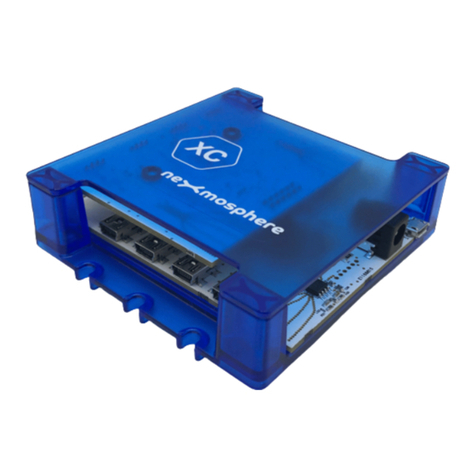
The XM-350 runs our API which provides serial output when a specic sensor Element is triggered (for example a pick-up,
or -motion sensor or touch button) and provides control over output Elements (for example controlling LED strips) via serial
input commands. These API serial commands are typically used to create interactive Xperiences for Digital Signage.
The complete API Manual and additional helpful documents can be found on https://nexmosphere.com/support-
documentation. To get you started, we’ve included some starter examples of our Elements and the corresponding API serial
commands on the following pages.
3rd party devices and software
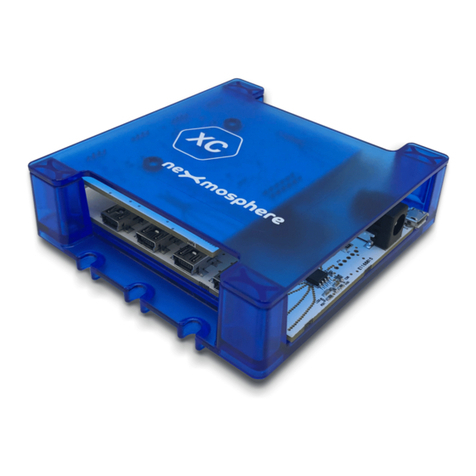
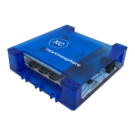
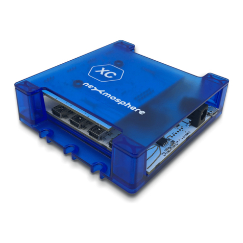
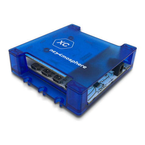
This Quick Start Guide oers a generic explanation of the setup and operation of the XM-350 controller with SM-100 ShopBus
Module. It does not cover information on how to integrate the Controllers, Elements and their API triggers in specic 3rd party
devices or software. We have manuals available with step-by-step instructions on how to integrate Nexmosphere products
with the products of our hardware, -and software partners. You’ll nd these on the support and partner pages of our website.
Nexmosphere
Le Havre 136
5627 SW Eindhoven • The Netherlands
T +31 40 240 7070
Esupport@nexmosphere.com
QUICK START GUIDE
© 2021 Nexmosphere. All rights reserved. v1.0 / 06-21
All content contained herein is subject to change without prior notice.
2
The RGB LED control commands for the SM-115 module are identical to the commands for the EM-6 module. To control
an RGB LED strip connected to RGB channel A, B, C, D or E of an SM-115 module, send one of the following API example
commands from the 3rd party device to the XM-350 controller:
Set the LED strip connected to RGB channel A of the RGB module with address 221 to color 0 (default white*) at 80%
brightness with 0.5 seconds ramp time:
*An overview of the default RGB LED colors is provided on the nal page of this document.
Set the LED strip of all 5 RGB channels (X) of the RGB module with address 221 to color 3 (default blue*) at 100% brightness
with 1.2 seconds ramp time:
Set the LED strip connected to RGB channel C of the RGB module with address 221 to pulse between 2 ramps. Ramp1: Color
2 (default green*) at 100% with 1.0 seconds ramp time. Ramp 2: Color 2 (default green*) at 5% with 0.5 seconds ramp time.
G221B[A 0 80 5]
G221B[X 3 100 12]
G221B[B 2 100 10 2 5 5]
+
B
DC24V
R
G
+
B
R
G
+
B
DC24V
R
G
+
B
R
G
+
B
DC24V
R
G
+
B
R
G
+
B
DC24V
R
G
+
B
R
G
+
B
DC24V
R
G
+
B
R
G
+
B
DC24V
R
G
+
B
R
G
+
B
DC24V
R
G
+
B
R
G
+
B
DC24V
R
G
+
B
R
G
Power supply
(24V)
ShopBus
cable
(to XM-350)
B A
E D C
21X221


