manuals.online logo
Brands
  1. Home
  2. •
  3. Brands
  4. •
  5. Nidec
  6. •
  7. Measuring Instrument
  8. •
  9. Nidec DT-200LR-S12 User manual

Nidec DT-200LR-S12 User manual

DT-200LR-S12 Handheld Digital Laser Tachometer
Operation Manual
• When using the 12” wheel, do not use the extension shaft - the wheel
may fly off the shaft and cause damage.
• Although the tachometer alone is able to achieve the higher
ranges listed in the Range and Accuracy table on page 3, the wheel
attachment has a maximum speed limitation of 5,000 FPM (for safety
reasons).
• Laser radiation may be harmful to the human eye. Avoid direct
exposure of human eyes to laser light. Eye damage can result.
•Never point the unit at another person.
•Keep out of the reach of children.
•Avoid indirect exposure via reflective materials such as glass and
mirrors.
SPECIFICATIONS
Display Range:6 - 99,999 rpm
Accuracy: ±1 rpm: 6 -8,300 rpm; ±2 rpm: 8,300 - 25,000 rpm;
±0.006% of reading ±1 digit (±6 rpm max.) 25,000 - 99,999 rpm
Display:5 digit 0.4” (10 mm) high LED
Measuring Units:rpm (on contact using adapter, included) for
YPM, mPM, FPM, IPM, and Length: YRD, m, FT and IN; Use wheel
with 200L adapter
Measuring Distance: 1” (25.4mm) to 20’ (6m)
Memory System:13 readings are stored in memory and retained
for 5 minutes (last, max., min., and 10 extra measurements)
Detection:Laser diode / contact
Update Time: 1 second (typical)
Power Requirement:2 AA 1.5V batteries (Life: Approx. 25 hrs)
Operating Temperature: 32º - 113ºF (0º - 45ºC)
Construction:Die-cast aluminum housing
Product Weight: 0.8 lb (365 g)
Package Weight:Approx. 2 lb (.91 kg)
Approvals:CE
Dimensions:6.6” L x 2.4” W x 1.8”H (167.5 mm x 60 mm x 46
mm); with contact adapter: Length=8.25” (209 mm)
Warranty:2-Year
Included Accessories: Reflective tape, 2 cone adapters, funnel
adapter, 3½” extension shaft, carrying case, NIST certificate, mas-
ter wheel (12” cir.) & contact adapter
Series DT-200LR Combination Contact/Non-Contact Laser Ta-
chometers Laser-enabled precise RPM measurement up to 20
feet. The Series DT-200LR digital tachometers incorporate laser
technology yet retain our hallmark rugged construction and reli-
able quality components. Units offer incredible value and versa-
tility as they can operate in non-contact and contact applications.
These instruments feature a field-upgradeable contact adapter for
linear rate measure, conveniently allowing both non-contact and
contact measurements. Incorporating the precise laser technol-
ogy and user-friendly functions as the DT-200LR tachometer, the
DT-200LR-S12 provides an exceptional accuracy in measuring
speed and length via its 12” wheel. The larger wheel rotates more
slowly than a standard 6” wheel, enabling reliable and safe regis-
tration of high speeds.
All Series 200LR units come standard with a NIST traceable cali-
bration certificate. We’re confident you’ll agree that these fine units
are the most advanced handheld tachometers on the market!
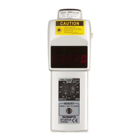
DT-205LR-S12
LCD Display
DT-207LR-S12
LED Display
When power button is depressed,
laser is active.
99 Washington Street
Melrose, MA 02176
Phone 781-665-1400
Toll Free 1-800-517-8431
Visit us at www.TestEquipmentDepot.com
2
OPERATION
Non-Contact Measurement
1. Place a small piece of reflective tape
(included) on the shaft or moving element
(disc, pulley, etc.) whose speed is to be
measured. If the element’s surface is highly
reflective it may need to be painted a dark-
er color in order to ensure reliable results.
If the distance to the object is less than 5”
(127 mm), reflective tabs (optional) should
be used instead of reflective tape.
2. Aim the tachometer at the reflective tape from a distance of 5”
(127 mm) to 20’ (6.m).
3. Press and hold the power switch for several seconds (when
power button is depressed, laser is active) to observe the display
as it changes according to the speed of the shaft or rotating ele-
ment (as soon as the laser hits the reflective tape, the unit will start
to indicate the speed). If the beam is “on target” the RPM indicator
will be flashing.
4. After observation is completed, retain the reading by releasing
the power switch (to turn off laser) before removing the tachome-
ter from its position. The last reading is displayed for a period of 5
minutes and can be extended any number of additional 5 minute
increments by pressing the memory switch.
NOTE: When switching from the contact to the non-contact mode,
the unit RPM will show on the display and also 5 dashes (-----).
Press the power switch to cancel the dashes.
Contact Measurement
For both RPM measurements and non-RPM measurements,
screw the DT-ADP-200LR Adapter (included) into the front of the
tachometer.
NOTE: Hand tightening is sufficient; do not use excessive torque
when mounting DT-ADP-200LR Adapter
RPM Measurement
1. Place rubber cone tip on the shaft of the
DT-ADP-200LR adapter. Make certain that the
pin on the shaft is properly aligned with the
slot on the cone’s sleeve.
2. Bring cone into contact with the shaft. Ap-
ply only enough pressure to avoid slippage.
3. Press and hold the power switch. During engagement the dis-
play will reflect the proper RPM while the unit RPM will be flashing
above the display digits.
4. Release the power switch prior to removal of tachometer from
rotating object to capture the last reading.
5. After release of the power switch, the last reading (with a
non-flashing RPM unit) will remain on the display and in memory
for 5 minutes, and can be extended any number of additional 5
minute periods by pressing the memory switch.
Rate & Length Measurement
1. Attach the master wheel and select the de-
sired function using the selector switch locat-
ed just below the LCD display (see above).
2. Press and hold the power switch; while the
wheel is turning and the tachometer is mea-
suring the selected function, the function will
be indicated, and the unit of measure func-
tion will be flashing.
3. Release the power switch before disengaging the tachometer
in order to capture the last reading.
4. After release of the power switch, the last, maximum, and mini-
mum readings will be stored in memory for 5 minutes and can be
extended any number of additional 5 minute periods by pressing
the memory button.
NOTE: The memory will clear in 5 minutes after the release of the
power switch.
For steps 1-4 described above, it was assumed that the selector
switch was in the rate mode region. If the selector switch is moved
from the rate mode to the count mode (length), the display will
show the selected function (m, ft, yd, or in) and also 5 dashes (----
-). Press the power switch to cancel the dashes and start measur-
ing the same way as was described above. Once in the counting
mode, the measurement can be stopped at any time and the last
reading will be retained for 5 minutes. There is no maximum or
minimum reading when in the count (length) mode.
CONTROL PANEL
MEMORY RECALL
The following readings are stored in memory for 5 minutes after
release of the power switch:
DT-205LR:
DT-207LR:
These readings can be recalled by pressing the memory switch.
During measurements, ten extra readings can also be captured,
stored, then recalled using the memory switch. While the tachom-
eter is in use, simply press the memory switch each time a read-
ing needs to be stored.
Contact Mode (Rate Functions)
When the rate functions are selected (mPM, YPM, FPM and 1PM),
the memory store and recall functions are accomplished exactly
as noted above.
Contact Mode (Length Functions)
When the counting functions are selected, the memory store and
recall functions are accomplished in the same manner as the
non-contact mode, the only exception being the maximum and
minimum readings (they do not exist).
Memory Clearing
To clear the memory (for all functions), press the memory switch
for approximately 5 seconds until the display shows” CCCCCC “.
Next, press the white Power switch or Memory switch. This resets
the tachometer for use.
BATTERY REPLACEMENT (2 each “M”)
Low battery voltage is indicated by flashing LOW BAT on the dis-
play. Remove end cover by using a coin or appropriate screw-
driver and replace both batteries. Please ensure proper polarity.
3
RANGE & ACCURACY
Place selector switch in the proper position. Using the DT-ADP-
200LR adapter and 12” master wheel, the following industrial units
of measurement are achieved:
NOTE: When using the 12” master wheel, accuracy can be affect-
ed as much as 0. 3% of reading
Although the tachometer alone is able to achieve the
above ranges, the master wheel has maximum
speed limitation of 6,000 FPM (for safety reasons)
R: REVOLUTIONS SINGLE RANGE ACCURACY RESOLUTION
Non-Contact RPM 6 - 8,300 ± 1
(rev./min.) 8,300 - 25,000 ± 2 1
25,000 - 99,999 ±0.006% of reading ±1digit
(or ±6 RPM max.)
Contact RPM (rev./min.) 0.8 - 9,999.9 ±0.6% 0.1
10,000 - 25,000 ±0.006% of reading ±1digit 1
(or ±2 RPM max.)
F: FEET SINGLE RANGE ACCURACY RESOLUTION
F/M (feet/min.) 0.8 - 9,999.9 ± 0.6 0.1
10,000 - 25,000 ± 1 1
FT (feet) 0.2 - 9999.8 0.01
10,000 - 99,999 0.1
Y: YARDS SINGLE RANGE ACCURACY RESOLUTION
Y/M (yards/min.) 0.25 - 999.99 ± 0.06 0.01
1,000.0 - 8,333.3 ± 0.3 0.1
YRd (length) 0.05 - 999.95 0.05
1,000.0 - 9,999.9 0.1
10,000 - 99,999 1
I: INCHES SINGLE RANGE ACCURACY RESOLUTION
I/M (inches/min.) 9 - 99,999 ±0.006% of reading ±1digit 1
(or ±6 RPM max.)
IN (length) 2 - 99,998 2
m: METERS SINGLE RANGE ACCURACY RESOLUTION
m/M (meters/min.) 0.23 - 999.99 ± 0.06 0.01
1,000.0 - 7,620.0 ± 0.3 0.1
m (length) 0.05 - 999.95 0.05
1,000.0 - 9,999.9 0.1
10,000 - 99,999 1
CAUTION
TROUBLESHOOTING
The following are general checkpoints; please call your local
Shimpo representative or contact Shimpo Instruments directly for
further assistance.
No laser beam is evident:
• Confirm that power switch is functioning
• Confirm that batteries are functioning and that polarity
is correct
Inaccurate measurement results:
• If the surface being measured is highly reflective, it may
need to be painted a darker color in order to ensure reliable
results
• Beam may not be hitting the reflective tape, or taped
area may be too small
• Measuring distance may be too short (unit must be at
least 5” from intended mark)
DIMENSIONS AND SPECIFICATIONS
12” Circumference Wheel
3.82”
(97.03 mm)
Test Equipment Depot - 800.517.8431 - 99 Washington Street Melrose, MA 02176
TestEquipmentDepot.com

This manual suits for next models

2

Other Nidec Measuring Instrument manuals

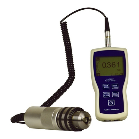
Nidec FG-7000T User manual

Nidec

Nidec FG-7000T User manual

Nidec DT-501X User manual

Nidec

Nidec DT-501X User manual

Nidec TNX Series User manual

Nidec

Nidec TNX Series User manual

Nidec ST-1100 User manual

Nidec

Nidec ST-1100 User manual

Nidec TNP Series User manual

Nidec

Nidec TNP Series User manual

Nidec MT-100 Installation manual

Nidec

Nidec MT-100 Installation manual

Nidec ST-1000 Installation manual

Nidec

Nidec ST-1000 Installation manual

Nidec Shimpo FG-L1 User manual

Nidec

Nidec Shimpo FG-L1 User manual

Nidec Shimpo DT-5TS User manual

Nidec

Nidec Shimpo DT-5TS User manual

Nidec PG-200 User manual

Nidec

Nidec PG-200 User manual

Nidec MF-2 User manual

Nidec

Nidec MF-2 User manual

Nidec MT-200 User manual

Nidec

Nidec MT-200 User manual

Nidec PG-100B Series User manual

Nidec

Nidec PG-100B Series User manual

Nidec FG-7000TA User manual

Nidec

Nidec FG-7000TA User manual

Nidec FG-3000R-S User manual

Nidec

Nidec FG-3000R-S User manual

Nidec ST-1100 User manual

Nidec

Nidec ST-1100 User manual

Nidec FGE-HXY Installation manual

Nidec

Nidec FGE-HXY Installation manual

Nidec ST-1100 User manual

Nidec

Nidec ST-1100 User manual

Nidec DT-361 User manual

Nidec

Nidec DT-361 User manual

Nidec Shimpo MT-200 User manual

Nidec

Nidec Shimpo MT-200 User manual

Nidec PG-35 User manual

Nidec

Nidec PG-35 User manual

Nidec MFD-02 User manual

Nidec

Nidec MFD-02 User manual

Nidec SHIMPO DT-5TXR User manual

Nidec

Nidec SHIMPO DT-5TXR User manual

Nidec FGV-HXY User manual

Nidec

Nidec FGV-HXY User manual

Popular Measuring Instrument manuals by other brands

Sekonic FLASHMATE L-308X Startup guide

Sekonic

Sekonic FLASHMATE L-308X Startup guide

Eastern Energy 840063 instruction manual

Eastern Energy

Eastern Energy 840063 instruction manual

Landis+Gyr T450 installation instructions

Landis+Gyr

Landis+Gyr T450 installation instructions

Vox VOX-01 quick start guide

Vox

Vox VOX-01 quick start guide

Leuze electronic AMS 200 Technical description

Leuze electronic

Leuze electronic AMS 200 Technical description

Trace2O OMAS manual

Trace2O

Trace2O OMAS manual

Water I.D. PoolLab2.0 user manual

Water I.D.

Water I.D. PoolLab2.0 user manual

USA Measurements US-M5 user manual

USA Measurements

USA Measurements US-M5 user manual

Hydrotechnik MultiSystem 5060 operating manual

Hydrotechnik

Hydrotechnik MultiSystem 5060 operating manual

Solar-Log 300 Connection manual

Solar-Log

Solar-Log 300 Connection manual

Siemens SIRIUS 3RR2143 A.30 Series operating instructions

Siemens

Siemens SIRIUS 3RR2143 A.30 Series operating instructions

Tektronix RSA306 installation instructions

Tektronix

Tektronix RSA306 installation instructions

Rothenberger RO 3200 Instructions for use

Rothenberger

Rothenberger RO 3200 Instructions for use

YOKOGAWA MT10 instruction manual

YOKOGAWA

YOKOGAWA MT10 instruction manual

carrierweb CARRIERMATE Diagnostics guide

carrierweb

carrierweb CARRIERMATE Diagnostics guide

Flomec TM Series Product owners manual

Flomec

Flomec TM Series Product owners manual

Autonics MT4Y Series product manual

Autonics

Autonics MT4Y Series product manual

Eastron SDM120C user manual

Eastron

Eastron SDM120C user manual

manuals.online logo
manuals.online logoBrands
  • About & Mission
  • Contact us
  • Privacy Policy
  • Terms and Conditions

Copyright 2025 Manuals.Online. All Rights Reserved.