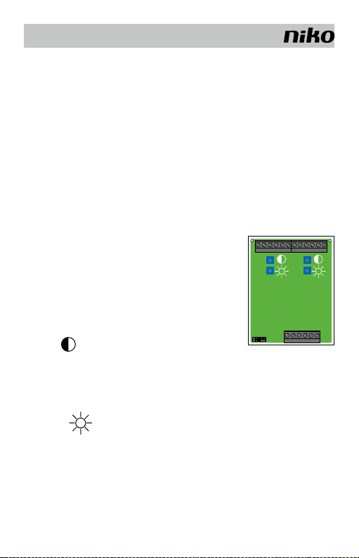
Niko 10-824-01 User manual

10-824-01
1
Lees de volledige handleiding vóór installatie en ingebruikname.
1. BESCHRIJVING
Videosplitter 10-824-01 wordt gebruikt voor verdeling van het videosignaal in een systeem
met sterbekabeling (fig.1). De videosplitter ontvangt het videosignaal en splitst het in 2
onafhankelijke video-uitgangssignalen.Na splitsing kan elk videosignaal afzonderlijk versterkt
worden.U wordt aangeraden de videosplitter aan het begin van een lijn (bij busvoeding 10-801
en gelijkspanningsvoeding 10-805-01) te plaatsen om de aanwezige stoorspanningen niet
mee te versterken (deze hebben een negatieve invloed op de beeldkwaliteit).
Welke kabels zijn nodig?
Niko raadt het volgende aan:
- JYSTY(-F2) min. 3 x 2 x 0,8mm
- TVVF (-F2) min. 3 x 2 x 0,8mm
- TPVF min. 3 x 2 x 0,6mm (Beperkt het aantal aan te sluiten componenten.Voor specificaties,
zie technische catalogus Niko Access Control).
Opmerking: Een kabel met 4 (getwiste) aderparen heeft als voordeel dat er voldoende
reserveparen zijn als een paar beschadigd wordt.
2. MONTAGE EN AANSLUITING
Deze videosplitter (fig.2a) is geschikt voor DIN-rail montage.
Voor de aansluiting van de bus en het videosignaal, zie fig.1 en 2.
➊ aansluitklemmen video-uitgang 1
➋ aansluitklemmen video-uitgang 2
➌ J1: afsluitweerstand
➍ J2: 5/6-draads bekabeling
➎ Aansluitklemmen video-ingang
NL
12345678910 11 12
14 15 16 17 18 19 20 21 22 23 24 25
13
14 15 16 17 18 19 20 21 22 23 24 25
678910 11
abPMV1 V2 abPMV1 V2
abPMV1 V2
OUT2OUT1
IN
10-824-01
➊➋
➌
➍➎

10-824-01
2
Grenswaarden voor lijn in-uit aansluiting:
- Max. 15 x 10-824-01 kunnen in lijn (in-uit) aangesloten worden.
LET OP: de laatste videosplitter in lijn moet m.b.v. een afsluitweerstand de video-bus
afsluiten.
- Max. 30 videobinnenposten per voeding 10-805-01.
- Aan elke video-uitgang van een video-inbouwsplitter 2 kunnen max. 6 videobinnenposten
in lijn (in – uit) doorverbonden worden.
Opmerking: gelieve voor grote en complexe systemen contact op te nemen met Niko.
6/5-draads bekabeling
Bij systemen met beperkte grootte kan voor 5-draads bekabeling gekozen worden. De
M-klem hoeft dan niet bekabeld te worden. Alle jumpers moeten dan op de 5-draads
bekabeling ingesteld worden.
3. WERKING EN GEBRUIK
Beeldkwaliteit
TIP: U regelt het contrast en de helderheid van het beeld best met 2 personen: iemand om
de potentiometers te bedienen en iemand om de beeldkwaliteit op de videobinnenposten
te volgen.
Open de videosplitter door de schroeven links en rechts bovenaan
los te draaien met een schroevendraaier. Verwijder de kap. Er
zijn 4 potentiometers (regelaars) zichtbaar.
Met de 2 linkse potentiometers kan u uitgang 1 aanpassen, met
de rechtse uitgang 2.
Contrast:
Door signaalverzwakking in de videobus (V1,V2) na splitsing kan
het beeldcontrast verminderen. Draai met een schroevendraaier aan de regelaar om het
beeldcontrast per video-uitgang aan te passen.
Wijzerzin: meer contrast
Tegenwijzerzin: minder contrast
Helderheid:
Door signaalverzwakking in de videobus (V1,V2) na splitsing kan de helderheid van het
beeld verminderen. Draai met een schroevendraaier aan de regelaar om de helderheid van
het beeld per video-uitgang aan te passen.
Wijzerzin: beeld wordt helderder.
Tegenwijzerzin: beeld wordt minder helder.
Plaats de kap op de videosplitter en draai de 2 schroeven, links en rechts boven, aan met
een schroevendraaier.
NL

10-824-01
3
Jumper J1 en J2
J1: afsluitweerstand bepalen
J1 horizontaal over beide onderste pinnen: videosplitters NIET als laatste
toestel op de video-bus
J1 verticaal over beide linkse pinnnen: videosplitter als laatste toestel op de
video-bus in een videosysteem.
J2: 5/6–draads bekabeling bepalen
J2 horizontaal over beide onderste pinnen: videosplitter in een videosysteem
dat 6-draads bekabeld is (klem b en klem M intern doorverbonden)
J2 verticaal over beide linkse pinnen:videosplitter gebruikt in een videosysteem
dat 5-draads bekabeld is
4. TECHNISCHE GEGEVENS
Voedingsspanning........................................ +24V ±8%
Behuizing .................................................... 4TE
Gewicht....................................................... 130g
Bedrijfstemperatuur .....................................0°C tot 40°c
Ingangsimpedantie J1 (afsluitweerstand........100Ω
Ingangsstroom............................................. I(a)=0,0mA; I(Pmax)=75mA
Signaalversterking........................................ 0dB tot +12dB* (lineair)
Maiximaal uitgangssignaal............................ 4Vpp*
* bij 1Vpp aan de ingang en een afsluitweerstand van 100Ω (J1)
5. WETTELIJKE WAARSCHUWINGEN
- De installatie dient te worden uitgevoerd door een bevoegd persoon en met inachtname
van de geldende voorschriften.
- Deze handleiding dient aan de gebruiker te worden overhandigd. Zij moet bij het dossier
van de elektrische installatie worden gevoegd en dient te worden overgedragen aan
eventuele nieuwe eigenaars. Bijkomende exemplaren zijn verkrijgbaar via de Niko-website
of -supportdienst.
- Bij de installatie dient rekening gehouden te worden met (lijst is niet limitatief):
- de geldende wetten, normen en reglementen;
- de stand van de techniek op het ogenblik van de installatie;
- het feit dat een handleiding alleen algemene bepalingen vermeldt en dient gelezen te
worden binnen het kader van elke specifieke installatie;
- de regels van goed vakmanschap.
- Bij twijfel kan u de supportdienst van Niko raadplegen of contact opnemen met een erkend
controleorganisme.
Support België: Support Nederland:
tel. + 32 3 778 90 80 tel. + 31 183 64 06 60
website: http://www.niko.be website: http://www.niko.nl
e-mail: support@niko.be e-mail: sales@niko.nl
NL

10-824-01
4
In geval van defect kan u uw product terugbezorgen aan een erkende Niko-groothandel
samen met een duidelijke omschrijving van uw klacht (manier van gebruik, vastgestelde
afwijking…).
6. GARANTIEBEPALINGEN
- G arantiet e r mijn: t wee jaar va n a f leverin g s datum. A ls leve r i n gsdatum g e l d t d e factuur d a t um
van aankoop van het goed door de consument. Indien geen factuur voorhanden is, geldt
de productiedatum.
- De consument is verplicht Niko schriftelijk over het gebrek aan overeenstemming te
informeren, uiterlijk binnen de twee maanden na vaststelling.
- In geval van een gebrek aan overeenstemming van het goed heeft de consument recht
op een kosteloze herstelling of vervanging, wat door Niko bepaald wordt.
- Niko is niet verantwoordelijk voor een gebrek of schade als gevolg van een foutieve
installatie, oneigenlijk of onachtzaam gebruik of verkeerde bediening of transformatie
van het goed.
- De dwingende bepalingen van de nationale wetgevingen betreffende de verkoop van
consumptiegoederen en de bescherming van de consumenten van de landen waarin Niko
rechtstreeks of via zuster/dochtervennootschappen, filialen, distributeurs, agenten of
vaste vertegenwoordigers verkoopt, hebben voorrang op bovenstaande bepalingen.
NL

10-824-01
5
Lisez entièrement le mode d’emploi avant toute installation et mise en service.
1. DESCRIPTION
Le répartiteur vidéo 10-824-01 est utilisé pour répartir le signal vidéo dans un système
à câblage en étoile (fig.2b). Le répartiteur vidéo reçoit le signal vidéo et le divise en 2
signaux de sortie vidéo indépendants. Après la séparation, chaque signal vidéo peut
être renforcé de manière indépendante. Nous vous conseillons de placer le répartiteur
vidéo au début d’une ligne (avec une alimentation bus 10-801 et une alimentation en
tension continue 10-805-01) pour ne pas renforcer simultanément les tensions parasites
présentes (elles influencent négativement la qualité de l’image).
Quels câbles sont nécessaires?
Niko vous conseille les types suivants:
- JYSTY(-F2) min. 3 x 2 x 0,8mm
- TVVF (-F2) min. 3 x 2 x 0,8mm
- TPVF min. 3 x 2 x 0,6mm (limite le nombre d’éléments raccordables. Pour les spécifi-
cations, voir le catalogue technique Niko Access Control).
Remarque:
Un câble avec 4 paires de conducteurs (torsadées) a l’avantage de prévoir suffisamment
de paires de réserve si l’une d’entre elles est endommagée.
2. MONTAGE ET RACCORDEMENT
Ce répartiteur vidéo est conçu pour un montage sur rail DIN.
Pour le raccordement du bus et du signal vidéo, voir fig.1 et 2.
➊ bornes de raccordement sortie vidéo 1
➋ bornes de raccordement sortie vidéo 2
➌ J1: résistance terminale
➍ J2: câblage 5/6 fils
➎ Bornes de raccordement sortie vidéo
FR
12345678910 11 12
14 15 16 17 18 19 20 21 22 23 24 25
13
14 15 16 17 18 19 20 21 22 23 24 25
678910 11
abPMV1 V2 abPMV1 V2
abPMV1 V2
OUT2OUT1
IN
10-824-01
➊➋
➌
➍➎

10-824-01
6
Limites pour un raccordement en ligne entrée-sortie:
- Max. 15 x 10-824-01 peuvent être raccordés en ligne (entrée-sortie).
ATTENTION: le dernier répartiteur vidéo de la ligne doit fermer le bus vidéo au moyen
d’une résistance terminale.
- Max. 30 postes intérieurs vidéo par alimentation 10-805-01.
- Max. 6 postes intérieurs vidéo peuvent être raccordés en ligne (entrée - sortie) à chaque
sortie vidéo d’un répartiteur vidéo 2 à encastrer.
Remarque: en cas de systèmes grandes et complexes, contactez Niko.
Câblage 6/5 fils
En cas de systèmes limités, le câblage à 5 fils suffit. La borne M ne doit pas être câblée.
Tous les cavaliers doivent alors être réglés sur le câblage à 5 fils.
3. FONCTIONNEMENT ET UTILISATION
Qualité de l’image
A S T U C E : R é glez de pré f érence le c o n t r a s te et la lum inosité de l ’imag e à d e ux: une perso n n e
s’occupe des potentiomètres et une autre suit l’évolution de la qualité de l’image sur les
postes intérieurs vidéo.
Ouvrez le r é p a r t i t e ur vidéo en de s s e r r a nt les vis en h a u t à gauche
et à droite à l’aide d’un tournevis. Retirez le capot. 4 potentio-
mètres (dispositifs de réglage) sont à présent visibles.
Les 2 potentiomètres de gauche permettent de régler la sortie
1, ceux de droite la sortie 2.
Contraste:
Le contraste de l’image peut diminuer en raison d’une atténuation du signal dans le bus
vidéo (V1, V2) après la séparation. Faites tourner le dispositif de réglage au moyen d’un
tournevis pour adapter le contraste de l’image par sortie vidéo.
Dans le sens horaire: plus contrast
Dans le sens antihoraire: moins contrast
Luminosité:
La luminosité de l’image peut diminuer en raison d’une atténuation du signal dans le bus
vidéo (V1, V2) après la séparation. Faites tourner le dispositif de réglage au moyen d’un
tournevis pour adapter la luminosité de l’image par sortie vidéo.
Dans le sens horaire: l’image devient plus claire.
Dans le sens antihoraire: l’image devient moins claire.
Replacez le capot sur le répartiteur vidéo et serrez les 2 vis, en haut à gauche et à droite,
à l’aide d’un tournevis.
FR

10-824-01
7
Cavaliers J1 et J2
J1: déterminer la résistance terminale
J1 à l’horizontale sur les deux broches inférieures: le répartiteur vidéo
N’EST PAS le dernier dispositif du bus vidéo
J1 à la verticale sur les deux broches de gauche: le répartiteur vidéo est le
dernier dispositif du bus vidéo dans un système vidéo.
J2: déterminer le câblage 5-/6 fils
J2 à l’horizontale sur les deux broches inférieures: le répartiteur vidéo est
utilisé dans un système vidéo qui est doté d’un câblage à 6 fils (les bornes b
et M sont raccordées en interne)
J2 à la verticale sur les deux broches de gauche: le séparateur vidéo est
utilisé dans un système vidéo qui est doté d’un câblage à 5 fils
4. CARACTERISTIQUES TECHNIQUES
Tension d’alimentation......................................... +24V ±8%
Boîtier................................................................. 4U
Poids .................................................................. 130g
Température de fonctionnement .......................... 0°C à 40°C
Impédance d’entrée J1 (résistance terminale ....... 100Ω
Courant d’entrée ................................................. I(a)=0,0 mA; I(Pmax)=75mA
Amplification du signal ........................................ de 0dB à +12dB* (linéaire)
Signal de sortie maximal .................................... 4Vpp*
* avec 1 Vpp à l’entrée et avec une résistance terminale de 100Ω (J1)
5. PRESCRIPTIONS LEGALES
- Lisez entièrement le mode d’emploi avant toute installation et mise en service.
- L’installation doit être effectuée par une personne compétente et dans le respect des
prescriptions en vigueur.
- Ce mode d’emploi doit être remis à l’utilisateur. Il doit être joint au dossier de l’installation
électrique et être remis à d’éventuels autres propriétaires. Des exemplaires supplémentaires
peuvent être obtenus sur le site web ou auprès du service ‘support Niko’.
- Il y a lieu de tenir compte des points suivants avant l’installation (liste non limitative):
- les lois, normes et réglementations en vigueur;
- l’état de la technique au moment de l’installation;
- ce mode d’emploi qui doit être lu dans le cadre de toute installation spécifique;
- les règles de l’art.
- En cas de doute, vous pouvez appeler le service ‘support Niko’ ou vous adresser à un
organisme de contrôle reconnu.
Support Belgique: Support France:
+ 32 3 778 90 80 + 33 820 20 6625
site web: http://www.niko.be site web: http://www.niko.fr
e-mail: support@niko.be e-mail: ventes@niko.fr
FR

10-824-01
8
En cas de défaut de votre appareil, vous pouvez le retourner à un grossiste Niko agréé,
accompagné d’une description détaillée de votre plainte (manière d’utilisation, divergence
constatée…).
6. CONDITIONS DE GARANTIE
- Délai de garantie: 2 ans à partir de la date de livraison. La date de la facture d’achat
par le consommateur fait office de date de livraison. Sans facture disponible, la date
de fabrication est seule valable.
- Le cons o m mateur e s t t e nu de prév e nir Niko p a r é c r it de tout ma n q u ement à la c o n c o rdance
des produits dans un délai max. de 2 mois après constatation.
- Au cas ou pareil manquement serait constaté, le consommateur a droit à une réparation
gratuite ou à un remplacement gratuit selon l’avis de Niko.
- Niko ne peut être tenu pour responsable pour un défaut ou des dégâts suite à une
installation fautive, à une utilisation contraire ou inadaptée ou à une transformation du
produit.
- Les dispositions contraignantes des législations nationales ayant trait à la vente de
biens de consommation et la protection des consommateurs des différents pays où
Niko procède à la vente directe ou par entreprises interposées, filiales, distributeurs,
agents ou représentants fixes, prévalent sur les dispositions susmentionnées.
FR

10-824-01
9
Read the complete manual before attempting installation and activating the
system.
1. DESCRIPTION
V ideo spli t ter 10 - 8 24- 01 is used fo r t h e distrib u t i o n of the vide o s i gnal wit h i n a st ar- c a b led
system (fig.1). The video splitter receives the video signal and splits it up in two separate
video outpu t s i gnals. A f t er split t ing, ev e r y v i d e o s ignal c a n b e a mplifie d s e p aratel y. Yo u are
recommended to place the video splitter at the beginning of a line (near bus power supply
10-801 and direct current power supply 10-805-01) in order to avoid also amplifying the
interference supplies (these negatively affect the image quality).
Which cables are required?
Niko recommends the following:
- JYSTY(-F2) min. 3 x 2 x 0.8mm
- TVVF (-F2) min. 3 x 2 x 0.8mm
- TPVF min. 3 x 2 x 0,6mm (Limits the number of components to be connected. For
specifications, see technical catalogue Niko Access Control).
Note: A cable with 4 (twisted) pairs has the advantage of offering sufficient spare pairs
in case one pair is damaged.
2. INSTALLATION AND CONNECTION
This video splitter is suitable for DIN-rail mounting.
For the connection of the bus and the video signal, see fig.1 and 2.
➊ connection terminals video output 1
➋ connection terminals video output 2
➌ J1: terminal resistor
➍ J2: 5/6-wire cabling
➎ connection terminals video output
EN
12345678910 11 12
14 15 16 17 18 19 20 21 22 23 24 25
13
14 15 16 17 18 19 20 21 22 23 24 25
678910 11
abPMV1 V2 abPMV1 V2
abPMV1 V2
OUT2OUT1
IN
10-824-01
➊➋
➌
➍➎

10-824-01
10
Limit values for line in-out connection:
- Max. 15 x 10-824-01 can be connected in line (in-out).
NOTE: the last video flush mounting splitter in line has to close off the video bus by
means of a terminal resistor.
- Max. 30 video internal units per power supply 10-805-01.
- At every video output of a video flush mounting splitter 2, max. 6 video internal units
can be connected in line (in-out).
Note: for large and complex systems, please contact Niko.
6/5-wire cabling
In case of limited systems, a 5-wire cabling suffices. In that case, the M terminal does
not have to be wired. All jumpers then have to be set to 5-wire cabling.
4. OPERATION AND USE
Image quality
TIP: Preferably adjust the image clarity with 2 people: one to control the controller and one
to check the image quality on the video internal units.
Open the video splitter by unscrewing the screws at the top
left and right by means of a screwdriver. Remove the cover. 4
potentiometers (controllers) are visible.
Output 1 can be ad j u s ted by me a n s o f t he 2 left potent i o meters,
output 2 by means of the right one.
Contrast:
Due to signal attenuation in the video bus (V1, V2) after splitting, the contrast of the
image can decrease. Turn the controller by means of a screwdriver to adjust the image
contrast per video output.
Clockwise: more contrast
Counterclockwise: less contrast
Brightness:
Due to signal attenuation in the video bus (V1, V2) after splitting, the brightness of the
image can decrease. Turn the control by means of a screwdriver to adjust the image
brightness per video output.
Clockwise: image becomes brighter
Counterclockwise: image becomes less bright.
Place the cover over the video plitter and screw-fix the 2 screws at the top left and right
by means of a screwdriver.
EN

10-824-01
11
Jumper J1 and J2
J1: defining terminal resistor
J1 horizontally over both bottom pins: video splitters NOT as last appliance
on the video bus
J1 vertically over both left pins: video splitter as last appliance on the
video bus
J2: defining 5/6-wire cabling
J2 horizontally over both bottom pins: video splitter used in a 6-wire video
system (terminal b and M interconnected)
J2 vertically over both left pins: video splitter used in a 5-wire video
system
4. TECHNICAL DATA
Supply voltage............................................. +24V ±8%
Cover.......................................................... 4U
Weight ........................................................ 130g
Operating temperature ................................ 0 to 40°C
Input impedance J1 (terminal resistor .......... 100Ω
Input current ............................................... I(a)=0,0mA; I(Pmax)=75mA
Signal gain..................................................0dB to +12dB* (linear)
Max. output signal....................................... 4Vpp*
* in case of 1Vpp at the input and terminal resistor of 100Ω (J1)
5. LEGAL WARNINGS
- The installation has to be carried out by a qualified person and in compliance with the
statutory regulations.
- This user manual has to be handed over to the user. It has to be included in the electri-
cal installation file and has to be passed on to any new owners. Additional copies are
available on the Niko website or via the support service.
- During installation, the following has to be taken into account (not limited to list below):
- The statutory laws, standards and regulations;
- The state of the art technique at the moment of installation;
- This user manual, which must be read within the scope of each specific installation,
only states general regulations;
- The rules of proper workmanship
- In case of questions, you can consult Niko’s support service or contact a registered
control organisation.
Support Belgium: Support UK:
+32 3 778 90 80 +44 1525877707
website : http://www.niko.be website: http://www.nikouk.com
EN

10-824-01
12
In case of a defect, you can return your product to a registered Niko wholesaler, together
with a clear description of your complaint (Conditions of use, stated defect…).
6. GUARANTEE PROVISIONS
- Period of guarantee: 2 years from date of delivery. The delivery date is the invoice date
of purchase of the product by the consumer. If there is no invoice, the date of production
applies.
- The consumer is obliged to inform Niko in writing about the defect, within two months
after stating the defect.
- In case of a failure to conform, the consumer has the right to a repair or replacement
(decided by Niko) free of charge.
- Niko cannot be held liable for a defect or damage as a result of an incorrect installation,
improper or careless use or wrong usage or transformation of the goods.
- The compulsory regulations of the national legislation concerning the sales of consumer
goods and the protection of the consumers in the countries where Niko sells, directly or
via sister or daughter companies, chain stores, distributors, agents or permanent sales
representatives, take priority over the rules and regulations mentioned above.
EN

10-824-01
13
fig.1
max.6
max.6
max.6
max.6
max.6
max.6
2
2
10-555
10-406
4/3
10-801 10-805-01
2
2
22
6/5
6/5
6/5
6/5
6/5
10-555
10-555
6/5
6/5
10-555
2
10-555
6/5
6/5
10-555
1
2
15
10-555
10-555
10-555
10-555
10-555
10-555

10-824-01
14
10-824-01
a b E P M K V1 V2
V1 V2
OUT1
Video OUT2
Video
IN
Video
a b E P M K V1 V2
230V~
aG b R P M V1 V2
16 17
1 3
230V~
5 7 9
23 24 29 31
10-801 10-805-01
max.15
max.6
10-555 10-560
10-556 10-555
max.6
ba
ba
P M
P M V1 V2
ba P M
V1 V2
a b E P M K V1 V2a b E P M K V1 V2
fig.2

10-824-01
15

10-824-01
16
nv Niko sa
Industriepark West 40, BE-9100 Sint-Niklaas, Belgium
tel.: + 32 3 778 90 00 — fax: + 32 3 777 71 20
e-mail: support@Niko.be — www.niko.be PM010-82401R08514
Table of contents
Languages:
Other Niko Accessories manuals

Niko
Niko 350-30010 User manual

Niko
Niko 16-670 User manual

Niko
Niko 10-822-01 User manual

Niko
Niko XXX-78100 User manual

Niko
Niko 170-65 01 Series Guide

Niko
Niko 78400 Series User manual

Niko
Niko 350-10012 User manual

Niko
Niko SERVODAN Minilux Sensor PIR 180 User manual

Niko
Niko 170-65358 User manual

Niko
Niko 05-363 User manual