Niko 10-521 User manual

1
10-521
NL
Lees de volledige handleiding vóór installatie en ingebruikname.
1. BESCHRIJVING
Dankzij de extra bel 10-521 uit het gamma Niko Toegangscontrole blijft een oproep niet ongehoord. De extra bel kan parallel geprogrammeerd worden
met 2 binnenposten of rechtstreeks op een beldrukknop. Het toestel wordt opgebouwd op de muur. Het belvolume kan bij installatie ingesteld worden en
voor elk type oproep (afkomstig van buitenpost, appartementsdeur of interne oproep) is er een afzonderlijke beltoon. De gebruiker kan het belsignaal
uitschakelen via een schakelaar onderaan het toestel.
Schakelaar om belsignaal uit te schakelen
Drukknoppen voor programmatie en instellingen
Uitbreekpoorten voor kabel
Jumper voor selectie 2-of 3-draads
Serienummer
Potentiometer om belvolume in te stellen
Rode en groene LED
2. INSTALLATIE
Bekabeling
De diameter van de aders bepaalt de maximale afstand die behaald kan worden. In onderstaande tabel vindt u een overzicht van de max. afstand (van
voeding tot binnen- of buitenpost) per type kabel. De max. afstand kan verdubbeld worden door 2 paren samen te nemen.
Diameter 0,5mm
(bv UTP CAT. 5E)
0,6mm
(bv TPVF)
0,8mm
(bv SVV, TVVF,JYSTY…)
Max.afstand 70m 100m 200m
2- of 3-draads bekabeling
Voor kleine systemen met 1 buitenpost kan de installatie 2-draads (a en b) bekabeld worden. Gebruik 3-draads (a, b en P voor extra voeding) in alle andere
gevallen. Bij 2-draads bekabeling kunnen er max. 2 binnenposten gelijktijdig worden opgeroepen, bij 3-draads max. 4.
Voeding Max # 10-521 Bekabeling
10-801 10 2-draads
10-802 40 2-draads
10-802 + 10-805-01 90 3-draads
Installatieschema:
✱ verwijder het lampje
abE P
ab E2P
12V 1A max
✱
E1

2
10-521
Montage
➥1
➥2Plaats de jumper aan de achterzijde van het toestel in de juiste positie:
Verbonden: 2-draads, a & b (standaard instelling)
Niet verbonden: 3-draads, a, b & P
➥3
kabeldoorvoer
3. PROGRAMMEREN EN INSTELLINGEN WIJZIGEN
Het toestel kan rechtstreeks aan een beldrukknop worden toegewezen en parallel worden geprogrammeerd aan 2 binnenposten.
Voor volgende types oproep werd een beltoononderscheid voorzien:
•afkomstigvanhoofdbuitenpost(metadres0)
•afkomstigvananderebuitenpost(meteenanderadres)
•beldrukknopaandeappartementsdeur(etagebeldrukknop)
•interneoproep
De beltoon kan gewijzigd worden.
Het programmeren en het wijzigen van de instellingen kan zowel handmatig als met het servicetoestel 10-870.
Programmeren met het servicetoestel 10-870
Koppel het servicetoestel aan de installatie via de aders a, b en P of via de voorziene connector aan de buitenpost. De serienummers van de binnen- en
buitenposten vind je terug op het toestel en kan je op uw installatieschema kleven om gemakkelijk te programmeren.
Voorbeeld serienummer:
U kan via het serienummer de bel op een beldrukknop programmeren net zoals u dit zou doen met een (2de) binnenpost.
NL

3
10-521
Andere mogelijkheden kan u terugvinden in onderstaande tabel:
Als SLAVE programmeren op binnenpost 1 * 40 # serienr. bel # serienr. binnenpost 1 #
Als SLAVE programmeren op binnenpost 2 * 40 # serienr. bel # serienr. binnenpost 2 #
SLAVE-programmatie 1 & 2 uitschakelen * 30 # serienr. bel # 101 #
Beltoonwijziging blokkeren * 30 # serienr. bel # 102 #
Programmeermodus blokkeren * 30 # serienr. bel # 103 #
Blokkering ongedaan maken * 30 # serienr. bel # 105 #
Terug naar fabrieksinstellingen * 30 # serienr. bel # 106 #
Beltoon instellen volgens onderstaande tabel * 30 # serienr. bel # beltoonnr. #
Beltoonnummers
Hoofdbuitenpost Andere buitenposten Appartementsdeur Interne oproep
0Alfatoon 1 20 40 60 80
1Alfatoon 2 21 41 61 81
2Alfatoon 3 22 42 62 82
3Alfatoon 4 23 43 63 83
4Alfatoon 5 24 44 64 84
5Alfatoon 6 25 45 65 85
6Gong enkel 26 46 66 86
7 Gong 2 x enkel 27 47 67 87
8 Gong 2 x dubbel 28 48 68 (*) 88
9 Gong 5 29 49 69 89
10 Alfatoon 3 x 30 (*) 50 70 90
11 Gong 4 x enkel 31 51 71 91
12 Gong 4 x dubbel 32 52 72 92
(*) beltoon bij levering
Handmatig de bel programmeren
De extra bel op een beldrukknop programmeren
1. Druk kort op de programmatieknop van de voeding om de programmatiemode te activeren (LED knippert).
2. Druk 2x kort op de beldrukknop aan de appartementsdeur met de extra bel (etagebeldrukknop).
3. Druk op de beldrukknop van de buitenpost.
4. Druk kort op de programmatieknop van de voeding om de programmatiemode uit te schakelen (LED brandt continu).
De extra bel parallel programmeren met een eerste binnenpost
1. Neem de hoorn op of activeer de spraakverbinding van de binnenpost. 1 2 3
2. Schakel het belsignaal van de extra bel uit en binnen de 2s weer aan.
3. Druk binnen de 2s op knop 1 en houd deze ingedrukt tot de rode LED knippert.
4. Druk kort op knop 2 achteraan op de bel (bevestigingstoon).
5. Haak de hoorn in of beëindig de spraakverbinding.
Om de bel ook met een tweede binnenpost te programmeren, herhaalt u bovenstaande stappen, maar druk bij stap 4 op knop 3.
Beltonen wijzigen
1. Schakel het belsignaal van de extra bel uit en binnen de 2s weer aan.
2. Druk binnen de 2s kort op knop 1 achteraan op de bel (rode LED knippert).
3. Druk meermaals kort op knop 3 om de beltonen voor de hoofdbuitenpost te doorlopen.
4. Druk meermaals kort op knop 2 om de beltonen voor de bel aan de appartementsdeur te doorlopen.
5. Wacht 8 seconden tot de rode LED ophoudt met knipperen.
6. De laatst gekozen beltonen werden opgeslagen.
4. TROUBLESHOOTING
Controleer bij problemen altijd eerst of de jumper juist geplaatst is.
Controleer met een multimeter of de volgende spanningen aanwezig zijn:
•tussenbena:ca.+24VDC
•tussenbenP:ca.+24VDC
Zie handleiding van de binnenpost voor meer troubleshootingtips.
NL

4
10-521
5. TECHNISCHE GEGEVENS
Voedingsspanning ...............................24V DC ±8%
Materiaal ............................................Kunststof
Afmeting.............................................98 x 98 x 12mm
Gewicht ..............................................92g
Toegelaten omgevingstemperatuur ......0° tot 40°C
Verbruik in werking .............................25 mA
Stand-by verbruik................................0,4 mA
Kleur...................................................Wit
6. WAARSCHUWINGEN VOOR INSTALLATIE
- De installatie moet worden uitgevoerd door een erkend installateur en volgens de geldende voorschriften.
- Deze handleiding moet aan de gebruiker worden overhandigd. Het moet bij het dossier van de elektrische installatie worden gevoegd en worden
overgedragen aan eventuele nieuwe eigenaars. Bijkomende exemplaren zijn verkrijgbaar via de website of supportdienst van Niko.
- Tijdens de installatie moet rekening gehouden worden met (niet-limitatieve lijst):
- de geldende wetten, normen en reglementen.
- de stand van de techniek op het moment van de installatie.
- deze handleiding die alleen algemene bepalingen vermeldt en moet worden gelezen in het kader van elke specifieke installatie.
- de regels van goed vakmanschap.
- Bij twijfel of voor de specifieke omruilprocedure in geval van een eventueel defect neemt u contact op met de Niko supportdienst (België: +32 3 778 90
80 – Nederland: +31 183 64 06 60) of uw groothandel. Contactgegevens en meer informatie vindt u op www.niko.eu onder de rubriek “Hulp en advies”.
GARANTIEBEPALINGEN
- De garantietermijn bedraagt vier jaar vanaf leveringsdatum. Als leveringsdatum geldt de factuurdatum
van aankoop van het product door de consument. Als er geen factuur voorhanden is, geldt de productiedatum.
- De consument is verplicht Niko schriftelijk te informeren over het gebrek aan overeenstemming, en dit uiterlijk binnen de twee maanden na vaststelling.
- In geval van een gebrek aan overeenstemming heeft de consument enkel recht op een kosteloze herstelling of vervanging van het product, wat door
Niko bepaald wordt.
- Niko is niet verantwoordelijk voor een defect of schade als gevolg van een foutieve installatie, oneigenlijk of onachtzaam gebruik, een verkeerde bedie-
ning, transformatie van het product, onderhoud in strijd met de onderhoudsvoorschriften of een externe oorzaak zoals vochtschade of schade door
overspanning.
- De dwingende bepalingen in de nationale wetgeving over de verkoop van consumptiegoederen en de bescherming van consumenten in landen waar
Niko rechtstreeks of via zuster- of dochtervennootschappen, filialen, distributeurs, agenten of vaste vertegenwoordigers verkoopt, hebben voorrang op
bovenstaande bepalingen.
NL

5
10-521
Lisez entièrement le mode d’emploi avant toute installation et mise en service.
1. DESCRIPTION
Grâce à la sonnerie supplémentaire 10-521 de la gamme NikoContrôle d’accès, vous ne manquerez plus jamais un appel. La sonnerie supplémentaire
peut être programmée en parallèle avec 2 postes intérieurs ou directement sur un bouton de sonnerie. L’appareil est monté en saillie sur le mur. Le
volume de la sonnerie peut être réglé lors de l’installation. En outre, une tonalité distincte est disponible pour chaque type d’appel (appel provenant du
poste extérieur, de la porte de l’appartement ou interne). L’utilisateur peut désactiver le signal d’appel au moyen d’un interrupteur situé sous l’appareil.
Interrupteur de désactivation du signal d’appel
Boutons-poussoirs pour la programmation et les réglages
Opercules défonçables pour le câble
Cavalier pour la sélection de 2 ou 3 fils
Numéro de série
Potentiomètre pour le réglage du volume de la sonnerie
LED verte et rouge
2. INSTALLATION
Câblage
Le diamètre des câbles détermine la distance maximale qui peut être couverte. Le tableau ci-dessous donne un aperçu de la distance maximale (depuis
l’alimentation jusqu’au poste intérieur ou extérieur) par type de câble. La distance maximale peut être doublée en prenant 2 paires ensemble.
Diameter 0,5mm
(bv UTP CAT. 5E)
0,6mm
(bv TPVF)
0,8mm
(bv SVV, TVVF,JYSTY…)
Max.afstand 70m 100m 200m
Câblage à 2 ou 3 fils
Dans les petits systèmes à 1 poste extérieur, l’installation peut être câblée au moyen d’un câble à 2 fils (a et b). Utilisez un câble à 3 fils (a, b et P pour
l’alimentation supplémentaire) dans tous les autres cas. Dans un câblage à 2 fils, maximum 2 postes intérieurs en même temps peut être sollicité;
dans un câblage à 3 fils, au maximum 4.
Alimentation Nombre max. -521 Câblage
10-801 10 2fils
10-802 40 2 fils
10-802 + 10-805-01 90 3 fils
Schéma d’installation:
✱ retirez la lampe
FR
abE P
ab E2P
12V 1A max
✱
E1

6
10-521
FR
Montage
➥1
➥2Placez le cavalier qui se trouve au dos de l’appareil dans la position correcte:
Connecté: 2 fils, a & b (configuration standard)
Non connecté: 3 fils, a, b & P
➥3
passe-câble
3. PROGRAMMATION ET MODIFICATION DES RÉGLAGES
L’appareil peut être attribué directement à un bouton de sonnerie et programmé en parallèle avec 2 postes intérieurs.
Une tonalité différente est prévue pour les types d’appels suivants :
•provenantduposteextérieurprincipal(avecadresse0)
•provenantd’unautreposteextérieur(avecuneautreadresse)
•boutondesonnerieàlaportedel’appartement(boutondesonneried’étage)
•appelinterne
La tonalité peut être modifiée.
La programmation et la modification des réglages peuvent s’effectuer manuellement ou au moyen de l’appareil de service 10-870.
Programmation avec l’appareil de service 10-870
Connectez l’appareil de service à l’installation au moyen des fils a, b et P ou du connecteur prévu sur le poste extérieur. Les numéros de série des postes
intérieur et extérieur se trouvent sur l’appareil et peuvent être collés sur votre schéma d’installation afin de faciliter la programmation.
Voorbeeld serienummer:
Vous pouvez programmer la sonnerie sur un bouton de sonnerie au moyen du numéro de série, comme vous le feriez pour un
(2e) poste intérieur.

7
10-521
FR
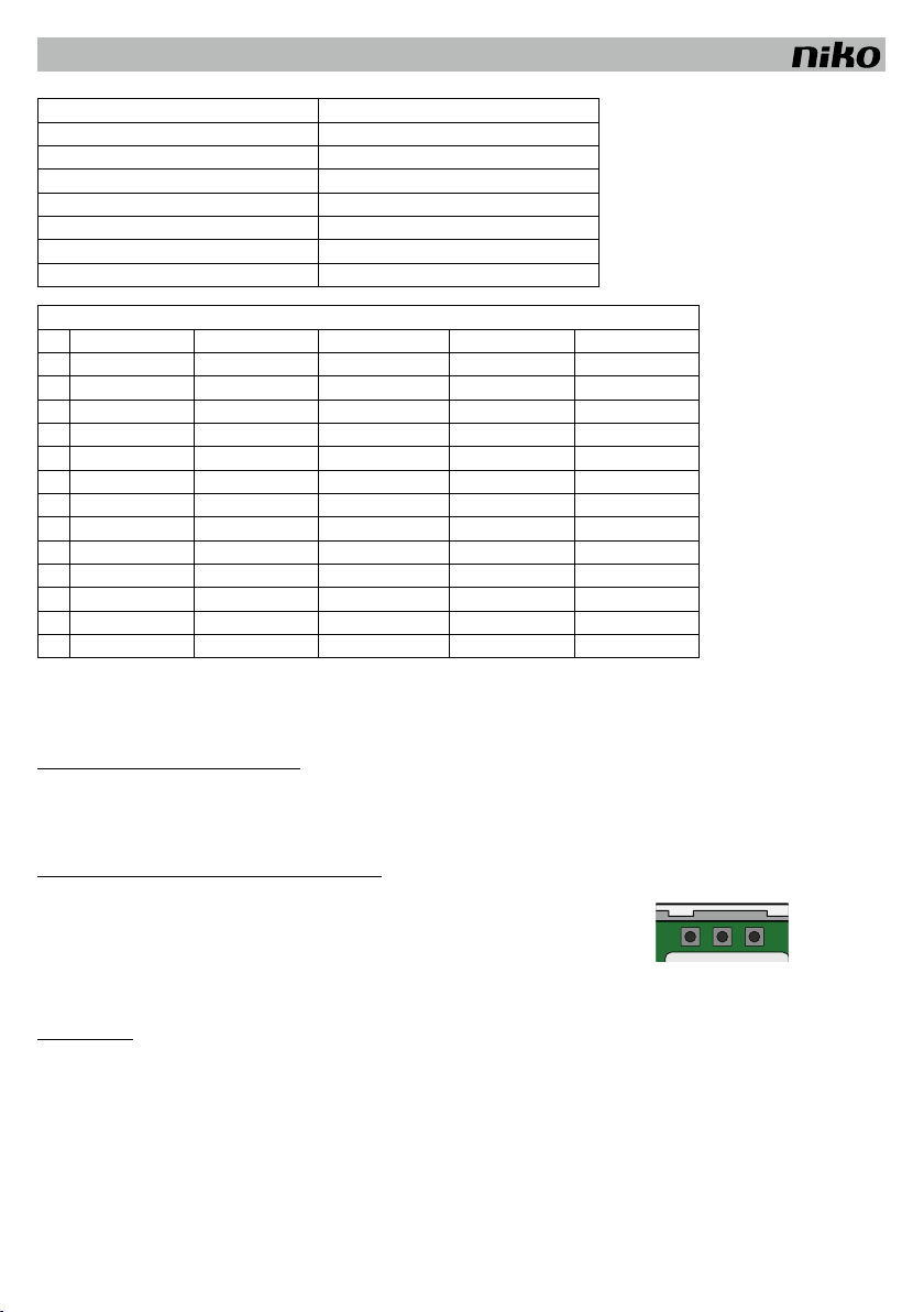
D’autres possibilités sont reprises dans le tableau ci-dessous :
Programmation comme ESCLAVE sur le poste intérieur 1 * 40 # n° série sonnerie # n° série poste intérieur 1 #
Programmation comme ESCLAVE sur le poste intérieur 2 * 40 # n° série sonnerie # n° série poste intérieur 2 #
Désactivation de la programmation comme ESCLAVE 1 & 2 * 30 # n° série sonnerie # 101 #
Blocage de la modification de la tonalité * 30 # n° série sonnerie # 102 #
Blocage du mode de programmation * 30 # n° série sonnerie # 103 #
Annulation du blocage * 30 # n° série sonnerie # 105 #
Retour aux réglages d’usine * 30 # n° série sonnerie # 106 #
Réglage de la tonalité selon le tableau ci-dessous * 30 # n° série sonnerie # n° tonalité #
Numéros des tonalités
Poste extérieur principal Autres postes extérieurs Porte de l’appartement Appel interne
0Tonalité alfa 1 20 40 60 80
1Tonalité alfa 2 21 41 61 81
2Tonalité alfa 3 22 42 62 82
3Tonalité alfa 4 23 43 63 83
4Tonalité alfa 5 24 44 64 84
5Tonalité alfa 6 25 45 65 85
6Gong simple 26 46 66 86
7 Gong 2 x simple 27 47 67 87
8 Gong 2 x double 28 48 68 (*) 88
9 Gong 5 29 49 69 89
10 Tonalité alfa 3 x 30 (*) 50 70 90
11 Gong 4 x simple 31 51 71 91
12 Gong 4 x double 32 52 72 92
(*) tonalité à la livraison
Programmation manuelle de la sonnerie
Programmation de la sonnerie supplémentaire sur un bouton de sonnerie
1. Appuyez brièvement sur le bouton de programmation de l’alimentation pour activer le mode de programmation (la LED clignote).
2. Appuyez brièvement 2 fois sur le bouton de sonnerie à la porte de l’appartement avec la sonnerie supplémentaire (bouton de sonnerie d’étage).
3. Appuyez sur le bouton de sonnerie du poste extérieur.
4. Appuyez brièvement sur le bouton de programmation de l’alimentation pour désactiver le mode de programmation (la LED est allumée en
continu).
Programmation de la sonnerie supplémentaire en parallèle avec un premier poste intérieur
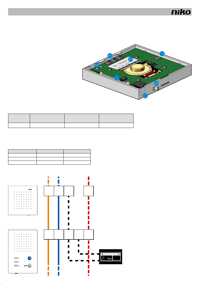
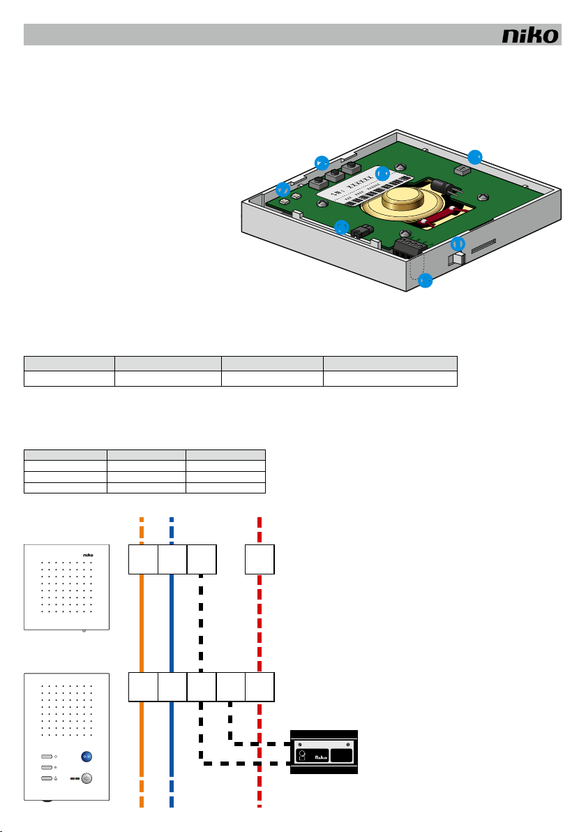
1. Décrochez le combiné ou activez la liaison vocale du poste intérieur. 1 2 3
2. Désactivez le signal d’appel de la sonnerie supplémentaire et réactivez-le dans les 2 secondes qui suivent.
3. Dans les 2 secondes qui suivent, appuyez sur le bouton 1 et maintenez le enfoncé jusqu’à ce que la LED rouge clignote.
4. Appuyez brièvement sur le bouton 2 à l’arrière de la sonnerie (tonalité de confirmation).
5. Raccrochez le combiné ou mettez fin à la liaison vocale.
Pour programmer la sonnerie avec un deuxième poste intérieur, procédez de nouveau comme indiqué ci-dessus, mais à l’étape 4, appuyez sur le bouton 3.
Modification des tonalités
1. Désactivez le signal d’appel de la sonnerie supplémentaire et réactivez-le dans les 2 secondes qui suivent.
2. Dans les 2 secondes qui suivent, appuyez brièvement sur le bouton 1 à l’arrière de la sonnerie (la LED rouge clignote).
3. Appuyez plusieurs fois brièvement sur le bouton 3 afin de parcourir les tonalités pour le poste extérieur principal.
4. Appuyez plusieurs fois brièvement sur le bouton 2 afin de parcourir les tonalités pour la sonnerie à la porte de l’appartement.
5. Attendez 8 secondes, jusqu’à ce que la LED rouge cesse de clignoter.
6. Les dernières tonalités sélectionnées sont alors enregistrées.
4. DÉPANNAGE
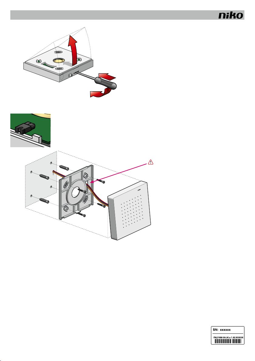
En cas de problème, assurez-vous toujours d’abord que le cavalier est bien positionné.
À l'aide d'un multimètre, contrôlez si les tensions suivantes sont présentes :
•entrebeta:env.+24VDC
•entrebetP:env.+24VDC
Pour plus de conseils de dépannage, consultez le manuel du poste intérieur.

8
10-521
FR
5. CARACTÉRISTIQUES TECHNIQUES
Tension d’alimentation.........................24 V DC ± 8%
Matériau .............................................Plastique
Dimensions.........................................98 x 98 x 12 mm
Poids ..................................................92 g
Température ambiante max.................de 0 à 40 °C
Consommation en fonctionnement.......25 mA
Consommation en veille.......................0,4 mA
Couleur...............................................Blanc
6. MISES EN GARDE CONCERNANT L’INSTALLATION
- L’installation doit être effectuée par un installateur agréé et dans le respect des prescriptions en vigueur.
- Ce mode d’emploi doit être remis à l’utilisateur. Il doit être joint au dossier de l’installation électrique et être remis aux nouveaux propriétaires éventuels. Des
exemplaires supplémentaires peuvent être obtenus sur le site web ou auprès du service support de Niko.
- Il y a lieu de tenir compte des points suivants pendant l’installation (liste non limitative):
- les lois, les normes et les réglementations en vigueur.
- l’état de la technique au moment de l’installation.
- ce mode d’emploi qui stipule uniquement des dispositions générales et doit être lu dans le cadre de toute installation spécifique.
- les règles de l’art.
- En cas de doute ou pour connaître la procédure d’échange spécifique en cas de défaut éventuel, veuillez prendre contact avec le service support de Niko
(Belgique: +32 3 778 90 80 – France: +33 820 20 66 25) ou avec votre grossiste. Vous trouverez les coordonnées et de plus amples informations sur le
site www.niko.eu, sous la rubrique “Aide et conseils”.
7. DISPOSITIONS DE GARANTIE
- Le délai de garantie est de quatre ans à partir de la date de livraison. La date de la facture d’achat par le consommateur est considérée comme la date de
livraison. En l’absence de facture, la date de fabrication est valable.
- Le consommateur est tenu de prévenir Niko par écrit de tout défaut de conformité, dans un délai maximum de deux mois après constatation.
- En cas de défaut de conformité, le consommateur peut uniquement prétendre à la réparation gratuite ou au remplacement gratuit du produit, selon l’avis
de Niko.
- Niko ne peut être tenu pour responsable d’un défaut ou de dégâts résultant d’une installation fautive, d’une utilisation impropre ou négligente, d’une
commande erronée, d’une transformation du produit, d’un entretien contraire aux consignes d’entretien ou d’une cause externe telle que de l’humidité ou
une surtension.
- Les dispositions contraignantes de la législation nationale ayant trait à la vente de biens de consommation et à la protection des consommateurs des différents
pays où Niko procède à la vente directe ou par l’intermédiaire d’entreprises sœurs, de filiales,de succursales, de distributeurs, d’agents ou de représentants
fixes, prévalent sur les dispositions susmentionnées.

9
10-521
Lesen sie sich die bedienungsanleitung vor der installation und inbetriebnahme sorgfältig durch.
1. BESCHREIBUNG
Dank der zusätzlichen Türklingel 10-521 aus der Produktreihe Niko Zugangskontrolle wird kein Rufsignal mehr überhört. Die zusätzliche Türklingel
lässt sich parallel zu 2 Innensprechstellen oder direkt zu einem Klingeltaster programmieren. Die Montage des Geräts erfolgt Aufputz auf der Mauer.
Bei der Installation kann die Ruftonlautstärke eingestellt werden. Für jeden Anruftyp (ob eingehend von Außensprechstelle, Wohnungstür oder bei einem
internen Anruf) steht ein spezifischer Rufton zur Verfügung. Der Benutzer kann über einen an der Geräteunterseite befindlichen Schalter das Rufsignal
abschalten.
SSchalter für Abschaltung des Rufsignals
Drucktasten für Programmierung und Geräteeinstellung
Vorbereitung für Kabeleinführung
Jumper für die Auswahl einer 2- oder 3-Draht-Verkabelung
Seriennummer
Potentiometer für Einstellung der Ruftonlautstärke
Rote und grüne LED
2. INSTALLATION
Verkabelung
Der Leitungsdurchmesser bestimmt die maximal zulässige Geräteentfernung. Untenstehende Tabelle bietet eine Übersicht über die je nach Kabeltyp
maximal zulässigen Entfernungslängen (zwischen Netzteil und Innen- bzw. Außensprechstelle). Die maximale Entfernung kann über die Zusammenlegung
von zwei Leitungen verdoppelt werden.
Durchmesser 0,5mm (z.B. UTP Cat. 5E) 0,6mm (z.B. TPVF) 0,8mm (z.B. SVV, TVVF, JYSTY...)
Max.Leitungslänge 70m 100m 200m
2- bzw. 3-Draht-Verkabelung
Kleine Zugangskontrollsysteme mit lediglich einer Außensprechstelle werden 2-drahtig (Leitungen a und b) verkabelt. In allen anderen Fällen erfolgt
der Anschluss 3-drahtig (Leitungen a, b und Leitung P für Netzteilanschluss). Bei einer 2-Draht-Verkabelung kann max. 2 Innenstationen zugleich
durchgeführt werden, bei einer 3-Draht-Verkabelung max. 4.
Voeding Max # 10-521 Bekabeling
10-801 10 2-draads
10-802 40 2-draads
10-802 + 10-805-01 90 3-draads
Installationsplan:
✱ Lampe entfernen!
DE
abE P
ab E2P
12V 1A max
✱
E1

10
10-521
Montage
➥1
➥2Jumper an der Geräterückseite auf richtige Position einstellen:
Gekoppelt: 2-Draht-Verkabelung, Leitungen a und b (standardmäßige Einstellung)
Nicht gekoppelt: 3-Draht-Verkabelung, Leitungen a, b und P
➥3
Kabelöffnung
3. GERÄT PROGRAMMIEREN UND EINSTELLUNGEN ÄNDERN
Das Gerät kann direkt einem Klingeltaster zugewiesen oder parallel zu 2 Innensprechstellen programmiert werden.
Für folgende Anruftypen besteht die Möglichkeit einer Ruftonunterscheidung:
•eingehendvonderHaupt-Außensprechstelle(mitAdresse0)
•eingehendvoneineranderenAußensprechstelle(mitandererAdresse)
•vomWohnungstür-Klingeltaster(Etagenklingelknopf)
•internerAnruf
Der Rufton kann geändert werden.
Die Programmierung und Änderung von Einstellungen kann sowohl manuell als auch über das Servicegerät 10-870 erfolgen.
Programmierung mit Servicegerät 10-870
Servicegerät über die Einzelleitungen a, b und P bzw. mit dem vorgesehenen Anschluss-Stecker an die Außensprechstelle der Anlageninstallation anschlie-
ßen. Die Seriennummern der Innen- und Außensprechstellen finden Sie hinten auf dem Gerät. Kleben Sie die Seriennummer auf
den Installationsplan, um so einfacher programmieren zu können.
Seriennummernbeispiel:
Mittels der Seriennummer können Sie die Türklingel auf einen Klingeltaster programmieren. Gehen Sie dabei so vor wie bei der
Programmierung einer (ggf. zweiten) Innensprechstelle.
DE

11
10-521
Untenstehende Tabelle enthält andere Programmiermöglichkeiten:
Programmierung als SLAVE von Innensprechstelle 1 * 40 # Seriennr. Türklingel # Seriennr. Innensprechstelle 1 #
Programmierung als SLAVE von Innensprechstelle 2 * 40 # Seriennr. Türklingel # Seriennr. Innensprechstelle 2 #
Programmierung als SLAVE 1 und 2 abschalten * 30 # Seriennr. Türklingel # 101 #
Ruftonänderung blockieren * 30 # Seriennr. Türklingel # 102 #
Programmiermodus blockieren * 30 # Seriennr. Türklingel # 103 #
Blockierung aufheben * 30 # Seriennr. Türklingel # 105 #
Rückkehr zu Werkseinstellungen * 30 # Seriennr. Türklingel # 106 #
Rufton nach untenstehender Tabelle einstellen * 30 # Seriennr. Türklingel # Ruftonnr. #
Ruftonnummern
Haupt-Außensprechstelle Weitere Außensprechstellen Wohnungstür Interner Anruf
0Alphaton 1 20 40 60 80
1Alphaton 2 21 41 61 81
2Alphaton 3 22 42 62 82
3Alphaton 4 23 43 63 83
4Alphaton 5 24 44 64 84
5Alphaton 6 25 45 65 85
6Gong, Einzelton 26 46 66 86
7Gong, 2 Einzeltöne 27 47 67 87
8Gong, 2 Doppeltöne 28 48 68 (*) 88
9 Gong 5 29 49 69 89
10 Alphaton, 3 mal 30 (*) 50 70 90
11 Gong, 4 Einzeltöne 31 51 71 91
12 Gong, 4 Doppeltöne 32 52 72 92
(*) bei Lieferung voreingestellter Rufton
Türklingel manuell programmieren
Zusätzliche Türklingel auf Klingeltaster programmieren
1. Drücken Sie für die Aktivierung des Programmiermodus kurz auf die Programmiertaste des Netzteils (LED blinkt).
2. Betätigen Sie 2 mal kurz den Klingeltaster an der mit der zusätzlichen Türklingel ausgestatteten Wohnungstür (Etagenklingelknopf).
3. Betätigen Sie den Klingeltaster der Außensprechstelle.
4. Drücken Sie für die Deaktivierung des Programmiermodus kurz die Programmiertaste des Netzteils (LED leuchtet dauerhaft).
Zusätzliche Türklingel parallel zur ersten Innensprechstelle programmieren
1. Nehmen Sie den Hörer ab oder aktivieren Sie die Sprechverbindung der Innensprechstelle. 1 2 3
2. Schalten Sie das Rufsignal der zusätzlichen Türklingel aus und innerhalb von 2 Sekunden wieder an.
3. Drücken Sie innerhalb von 2 Sekunden auf Taste 1 und halten Sie diese gedrückt, bis die rote LED blinkt.
4. Drücken Sie kurz auf die hinter der Türklingel befindliche Taste 2 (Bestätigungssignal).
5. Legen Sie den Hörer auf bzw. beenden Sie die Sprechverbindung.
Wiederholen Sie obenstehende Schritte, um die Türklingel auch auf eine zweite Innensprechstelle zu programmieren, aber drücken Sie bei Schritt 4 auf 3.
Ruftöne ändern
1. Schalten Sie das Rufsignal der zusätzlichen Türklingel aus und innerhalb von 2 Sekunden wieder an.
2. Drücken Sie innerhalb der 2 Sekunden kurz auf die hinter der Türklingel befindliche Taste 1 (rote LED blinkt).
3. Drücken Sie mehrmals kurz auf Taste 3, um die Ruftöne der Haupt-Außensprechstelle zu durchlaufen.
4. Drücken Sie mehrmals kurz auf Taste 2, um die Ruftöne für die Türklingel an der Wohnungstür zu durchlaufen.
5. Warten Sie 8 Sekunden, bis die rote LED aufhört zu blinken.
6. Die zuletzt gewählten Ruftöne werden gespeichert.
4. FEHLERSUCHE
Überprüfen Sie bei Problemen erst die richtige Jumperstellung.
Messen Sie mit einem Multimeter an folgenden Punkten auf richtige Spannungswerte:
•Zwischenbunda:ca.+24VDC
•ZwischenbundP:ca.+24VDC
Mehr Tipps zur Fehlerbehebung können Sie dem Handbuch der Innensprechstelle entnehmen.
DE

12
10-521
5. TECHNISCHE DATEN
Versorgungsspannung.........................24 V DC ± 8%
Material ..............................................Kunststoff
Abmessung.........................................98 x 98 x 12 mm
Gewicht ..............................................92 g
Zulässige Umgebungstemperatur ........0 °C bis 40 °C
Stromaufnahme während Betrieb ........25 mA
Standby-Stromaufnahme ....................0,4 mA
Farbe..................................................Weiß
6. WARNHINWEISE FÜR DIE INSTALLATION
- Die Installation darf ausschließlich von einer Elektrofachkraft unter Berücksichtigung der geltenden Vorschriften ausgeführt werden.
- Diese Gebrauchsanleitung muss dem Benutzer ausgehändigt werden.Die Gebrauchsanleitung ist den Unterlagen der elektrischen Anlage beizufügen und muss
auch eventuellen neuen Besitzern ausgehändigt werden. Zusätzliche Exemplare erhalten Sie über die Internetseiten von Niko oder über den Kundendienst
von Niko.
- Beachten und berücksichtigen Sie bei der Installation unter anderem folgende Punkte:
- die gültigen Gesetze, Normen und Richtlinien.
- den Stand der Technik zum Zeitpunkt der Installation.
- die in dieser Gebrauchsanleitung aufgeführten Anweisungen, wobei diese Gebrauchsanleitung nur allgemein gültige Bestimmungen enthält, die für jede
Anlage spezifisch angewendet werden müssen.
- die allgemein anerkannten Regeln fachmännischer Arbeit.
- Bei Zweifel oder falls Sie bei einem eventuellen Defekt des Produkts noch Fragen bezüglich des Umtausches haben, dann nehmen Sie bitte Kontakt auf mit
dem Kundendienst von Niko (Belgien: +32 3 778 90 80) oder wenden Sie sich an Ihren Großhändler. Kontaktdaten und weitere Informationen erhalten Sie
im Internet unter www.niko.eu in der Rubrik “Help and advice” (“Hilfe und Ratschläge”).
7. GARANTIEBEDINGUNGEN
- Der Garantiezeitraum beträgt vier Jahre ab Lieferdatum.Als Lieferdatum gilt das Rechnungsdatum zum Zeitpunkt des Kaufs durch den Endverbraucher. Falls
keine Rechnung mehr vorhanden ist, gilt das Produktionsdatum.
- Der Endverbraucher ist verpflichtet, Niko schriftlich über einen Produktmangel innerhalb von zwei Monaten nach dessen Feststellung zu informieren.
- Im Falle eines Mangels hat der Endverbraucher nur Recht auf kostenlose Reparatur oder Ersatz des Produkts. Eine Entscheidung darüber obliegt allein Niko.
- Niko ist nicht für Mängel oder Schäden verantwortlich, die durch fehlerhafte Installation, nicht bestimmungsgemäßen oder unsachgemäßen Gebrauch, durch
falsche Bedienung, Anpassen/Ändern des Produktes, infolge von unsachgemäßer Wartung entgegen den Wartungsvorschriften oder die sich aus äußeren
Umständen, wie beispielsweise infolge Feuchtigkeit oder Überspannung, ergeben.
- Zwingende Vorschriften der nationalen Gesetzgebung bezüglich des Verkaufs von Konsumgütern und zum Verbraucherschutz haben vor den obigen Bestim-
mungen Vorrang in den Ländern, in denen Niko direkt oder über seine Neben- oder Tochtergesellschaften, Filialen,Vertriebsstellen,Agenten oder über feste
Vertreter verkauft.
DE

13
10-521
Read the complete manual before carrying out the installation and activating the system.
1. DESCRIPTION
Thanks to the extra bell 10-521 from the Niko Access Control range, calls at your door never go unheard. The extra bell can be programmed in parallel
with 2 external units or directly to the bell push button. The device is surface mounted on the wall. The ring volume can be set during installation, and
there is a different ring tone for each type of call (originating from an external unit, an apartment door or from an internal call). The user can deactivate
the ring tone by using the switch on the underside of the device.
Switch to deactivate the ring tone
Push buttons for programming and settings
Knockouts for cable
Jumper for selection of 2-wire or 3-wire installation
Serial number
Potentiometer for setting ring volume
Red and green LED
2. INSTALLATION
Cabling
The diameter of the wires determines the max. distance that can be covered. In the table below, you see an overview of the maximum distance allowable
(from power supply to internal or external unit) per cable type. The maximum distance can be doubled by taking 2 pairs together.
Diameter 0,5mm
(bv UTP CAT. 5E)
0,6mm
(bv TPVF)
0,8mm
(bv SVV, TVVF,JYSTY…)
Max.afstand 70m 100m 200m
2- or 3-wire cabling
For small systems with 1 external unit, the installation can be wired with 2 wires (a and b). Use 3 wires (a, b, and P for extra power supply) in all other cases.
With 2-wire cabling, a max. of 2 internal units simultaneously can be made; with 3-wire cabling, a max. of 4 calls at a time can be made.
Power supply Max # 10-521 Cabling
10-801 10 2-wire
10-802 40 2-wire
10-802 + 10-805-01 90 3-wire
Installation diagram:
✱ remove the lamp
EN
abE P
ab E2P
12V 1A max
✱
E1

14
10-521
Installation
➥1
➥2Position the jumper on the rear of the device in the correct position:
Connected: 2-wire, a & b (standard set-up)
Not connected: 3-wire, a, b & P
➥3
cable inlet
3. PROGRAMMING AND MODIFYING SETTINGS
The device can be assigned directly to a bell push button and be programmed in parallel to 2 internal units.
A different ring tone is provided for the following types of call:
•originatingfromthemainexternalunit(withaddress0)
•originatingfromanotherexternalunit(withanotheraddress)
•bellpushbuttonattheapartmentdoor(floorbellpushbutton)
•internalcall
The ring tone can be changed.
Programming and the modification of the settings can occur either manually or with the service unit 10-870.
Programming with the service unit 10-870
Connect the service unit to the installation via the a, b and P wires or to the external unit via the connector provided. The serial numbers of the internal and
external units are located on the devices, and can be affixed to your installation diagram for easy programming.
Example of a serial number:
Using the serial number, you can program the bell to the bell push button just as you would with a (2nd) internal unit.
EN

15
10-521
Other possibilities are listed below:
Program as SLAVE on internal unit 1 * 40 # serial no. bell # serial no. internal unit 1 #
Program as SLAVE on internal unit 2 * 40 # serial no. bell # serial no. internal unit 2 #
Deactivate SLAVE programming 1 & 2 * 30 # serial no. bell # 101 #
Block ring tone modification * 30 # serial no. bell # 102 #
Block programming mode * 30 # serial no. bell # 103 #
Undo blocking * 30 # serial no. bell # 105 #
Back to factory defaults * 30 # serial no. bell # 106 #
Set ring tone according to the table below * 30 # serial no. bell # ring tone no. #
Ring tone numbers
Main external unit Other external units Apartment door Internal call
0Alpha tone 1 20 40 60 80
1Alpha tone 2 21 41 61 81
2Alpha tone 3 22 42 62 82
3Alpha tone 4 23 43 63 83
4Alpha tone 5 24 44 64 84
5Alpha tone 6 25 45 65 85
6Chime single 26 46 66 86
7 Chime 2 x single 27 47 67 87
8 Chime 2 x double 28 48 68 (*) 88
9 Chime 5 29 49 69 89
10 Alpha tone 3 x 30 (*) 50 70 90
11 Chime 4 x single 31 51 71 91
12 Chime 4 x double 32 52 72 92
(*) ring tone setting at delivery
Programming the bell manually
Programming the extra bell to a bell push button
1. Press the programming button on the power supply briefly to activate the programming mode (LED flashes).
2. Press the bell push button at the apartment door 2x briefly with the extra bell (floor bell push button).
3. Press the bell push button of the external unit.
4. Press the programming button of the power supply briefly to deactivate the programming mode (LED burns continuously).
Programming the extra bell in parallel with a first internal unit
1. Pick up the receiver or activate the speech connection of the internal unit. 1 2 3
2. Switch off the ring tone of the extra bell and switch it back on again within 2 sec.
3. Within 2 sec, press and hold button 1 until the red LED flashes.
4. Press briefly on button 2 on the rear of the bell (confirmation tone).
5. Replace the receiver or end the speech connection.
To program the bell with a second internal unit, repeat the steps above, but in step 4, push 3.
Modifying ring tones
1. Switch off the ring tone of the extra bell and switch it back on again within 2 sec.
2. Within 2 sec, press briefly on button 1 at the rear of the bell (red LED flashes).
3. Repeatedly press button 3 briefly to go through the ring tones for the main external unit.
4. Repeatedly press button 2 briefly to go through the ring tones for the bell at the apartment door.
5. Wait 8 seconds until the red LED stops flashing.
6. The ring tones chosen last are saved.
4. TROUBLESHOOTING
In case of problems, always first check whether the jumper is positioned correctly.
Using a multimeter, check whether the following voltages are present:
•betweenbanda:approx.+24VDC;
•betweenbandP:approx.+24VDC;
See the user manual of the internal unit for more troubleshooting tips.
EN

16
10-521
5. TECHNICAL DATA
Power supply voltage...................................24V DC ± 8%
Material ...................................................... Plastic
Dimensions.................................................98 x 98 x 12 mm
Weight ........................................................ 92 g
Permissible ambient temperature ................0° to 40°C
Power consumption during operation........... 25 mA
Power consumption in stand-by...................0.4 mA
Colour......................................................... White
6. WARNINGS REGARDING INSTALLATION
- The installation should be carried out by a registered installer and in compliance with the statutory regulations.
- This user manual should be presented to the user. It should be included in the electrical installation file, and it should be passed on to any new owners.
Additional copies are available on the Niko website or via the Niko support service.
- During installation, the following should be taken into account (non-exhaustive list):
- the statutory laws, standards and regulations.
- the technology currently available at the time of installation.
- this user manual, which only states general regulations and should therefore be read within the scope of each specific installation.
- the rules of proper workmanship.
- In case of doubt or for the specific exchange procedure in case of a possible defect, contact the Niko support service (Belgium: +32 3 778 90 80 – United
Kingdom: +44 1525 877 707) or your wholesaler. Contact details and more information can be found at www.niko.eu under the “Help and advice”
section.
7. GUARANTEE PROVISIONS
- The period of guarantee is four years from the date of delivery. The delivery date is the invoice date of purchase of the product by the consumer. If there is
no invoice, the date of production applies.
- The consumer is obliged to inform Niko in writing about the non-conformity, within two months after stating the defect.
- In case of a non-conformity, the consumer only has the right to a product repair or replacement free of charge, which shall be decided by Niko.
- Niko shall not be held liable for a defect or damage resulting from incorrect installation, improper or careless use, incorrect operation, transformation of the
product, maintenance that does not adhere to the maintenance instructions or an external cause, such as damage due to moisture or overvoltage.
- The compulsory regulations of the national legislation concerning the sale of consumer goods and the protection of the consumer in the countries where
Niko sells, directly or via sister companies, subsidiaries, chain stores, distributors, agents or permanent sales representatives, take priority over the above-
mentioned rules and regulations.
nv Niko sa Industriepark West 40, BE-9100 Sint-Niklaas
tel +32 (0)3 778 90 00 — fax +32 (0)3 777 71 20
EN
Table of contents
Languages:
Other Niko Accessories manuals