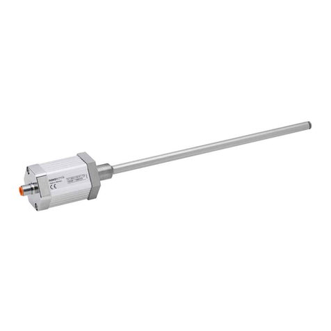
TH1 Gebrauchsanleitung
TH1 User manual
402519573/10 Änderungen vorbehalten / Subject to change 2022/12
4Montagehinweis
Für die direkte Hubmessung im Zylinder wird der
Positionsgeber mit 2 Schrauben M3 oder M4 (je nach
Positionsgeber) direkt auf dem Kolbenboden montiert,
Anzugsmoment für M4 Schrauben max. 1 N. Alternativ
kann der Positionsgeber auch durch einen Schraubring
oder eine Einpressverbindung fixiert werden.
Für die Aufnahme des magnetischen Positionsgebers ist
möglichst nichtmagnetisches Material (z.B. Edelstahl,
Messing, Aluminium) zu verwenden. Gegebenenfalls ist
eine nichtmagnetische Distanzscheibe (min. 5 mm stark)
zwischen Positionsgeber und Kolbenboden zu montieren.
Der Positionsgeber darf nicht auf dem Stab schleifen.
Wird der Schraubflansch in einen Zylinder aus
magnetisierbarem Material eingebaut, dann ist unbedingt
darauf zu achten, dass der Abstand zwischen
Positionsgeber in der Nullpunktstellung und dem Zylinder
min. 15 mm axial beträgt!
Bei den Varianten mit mehreren Positionsgebern muss
der Abstand zwischen den Positionsgebern jeweils min.
100 mm betragen! Das erste Positionssignal wird für den
Positionsgeber ausgegeben, der dem elektrischen Abgang
am nächsten ist.
Starke elektrische oder magnetische Felder in
unmittelbarer Nähe des Wegaufnehmers können
zu fehlerhaften Signalen führen.
Der Sensor wird mit Hilfe des Sechskantflansches (SW46)
eingeschraubt. Das Anschraubmoment darf 50Nm nicht
überschreiten!
Die Bohrung in der Kolbenstange ist abhängig vom Druck
und der Verfahrgeschwindigkeit auszulegen. Der
empfohlene Bohrungsdurchmesser beträgt Dk 12,7 mm.
Der mitgelieferte O-Ring dichtet den Druckbereich des
Zylinders am Einschraubloch ab. Die Flanschauflagefläche
muss vollständig an der entsprechenden Auflagefläche des
Zylinders aufliegen.
Bei waagrechter Montage von Wegaufnehmern mit einem
elektrisch definierten Bereich über 1000 mm empfiehlt es
sich, den TH1-Stab am Ende abzustützen.
Das Ende des TH1-Stabes ist vor Verschleiß zu schützen.
Der Bereich für den Kabelabgang muss ausreichend
dimensioniert werden, der Mindestbiegeradius ist
einzuhalten und scharfe Kanten sind zu vermeiden!
5Anschlüsse
Beim elektrischen Anschluss unbedingt zu beachten:
Anlage (Versorgung GND) und Schaltschrank (Signal GND)
müssen auf gleichem Potential liegen.
Um die elektromagnetische Verträglichkeit (EMV) zu
gewährleisten, sind nachfolgende Hinweise unbedingt zu
beachten*:
•Wegaufnehmer und Steuerung müssen mit einem
geschirmten Kabel verbunden werden.
•Schirmung: Geflecht aus Kupfer-Einzeldrähten,
85% Bedeckung.
•Auf der Seite der Steuerung muss der Kabelschirm
geerdet, d.h. mit dem Schutzleiter verbunden werden.
•Eine Verlängerung des Anschlusskabels auf
> 30 m bedeutet den Verlust der CE-Freigabe !
*) Für Sensoren mit IO-Link Schnittstelle können
ungeschirmte Verbindungsleitungen verwendet werden,
max. Leitungslänge 20 m.
4Instruction for installation
For direct stroke measurement in a cylinder the position
marker has to be fixed with 2 screws M3 or M4 (depending
on the position marker) directly on the cylinder‘s piston
bottom,fastening torque for M4 screws max. 1 Nm.
Alternatively the position marker can also be fixed by a
threaded ring or by an press-fit-connection. For the mounting
of the position marker non-magnetic material (e.g. stainless
steel, brass, aluminum) has to be used preferably.
If necessary a non-magnetic spacer with min. 5 mm thickness
has to be mounted between position marker and the
cylinder‘s piston bottom. The position marker may not drag
on the rod.
When the screw flange will be mounted in a cylinder of
magnetizable material, it‘s important to have an axial spacing
of min. 15 mm between position marker in setting to zero
point and cylinder!
For the versions with several position markers the distance
between the position markers must be min. 100 mm!
The first position signal is output for the position marker
which is closest to the electrical outlet
Strong electrical or magnetic fields in the
immediate vicinity of the transducer may lead to
faulty signals.
The sensor has to be screwed in via the hexagonal flange
(SW46). The maximum tightening torque must never exceed
50 Nm when fastening down the sensor head!
The bore in the piston rod has to be laid out dependent on
the pressure and the velocity of the movement.
The recommended bore diameter is Dk
12,7 mm.
The provided O-ring seals the pressure area of the cylinder at
the screw plug hole. The contact surface of the flange must
rest completely against the mounting surface of the cylinder.
For horizontal mounting of the transducer with a defined
electrical range longer than 1000 mm the TH1 rod should be
supported or attached at ist end.
The end of the TH1 rod has to be protected against wear.
For the area of the cable mount please take care that enough
space is available, the minimum bending radius has been
observed and sharp edges have be avoided.
5 Wiring
Note the following when making electrical connection:
System (supply voltage GND) and control cabinet (signal
GND) must be at the same potential.
To ensure the electromagnetic compatibility (EMC), the
following instructions must be strictly followed:
•Transducer and controller must be connected by using a
shielded cable.
•Shielding: Copper filament braided, 85% coverage.
•On the controller side the cable shield must be grounded,
i.e. be connected with the protective earth conducter.
Elongation of the cable connection to more than
30 m results in loss of CE compliance !
*) Sensors with IO-Link interface may be connected using an
unshielded cable. Max. cable length is 20 m.
Seite / page 4


