manuals.online logo
Brands
  1. Home
  2. •
  3. Brands
  4. •
  5. novotechnik
  6. •
  7. Transducer
  8. •
  9. novotechnik T Series User manual

novotechnik T Series User manual

T/TS/TR/TRS Gebrauchsanleitung
T/TS/TR/TRS Manual
P/N 403002747/00 Änderungen vorbehalten / Subject to change without notice 2020/06
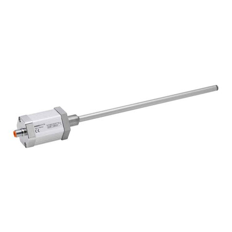
1Allgemeine Beschreibung
Die Baureihe T/TR ist ein potentiometrischer Wegaufnehmer für
direkte, genaue und absolute Messung von Wegen bzw. Längen
in der Steuerungs-, Regelungs- und Messtechnik.
2Sicherheitshinweise
Unsere Produkte sind regelmäßig nicht für Luft- und
Raumfahrtanwendungen zugelassen und dürfen nicht in
kerntechnischen oder militärischen, insbesondere ABC-relevanten
Applikationen verwendet werden.
Weitere Informationen s. unsere AGBs.
2.1 Bestimmungsgemäße Verwendung
Der Wegaufnehmer wird zu seiner Verwendung in eine Maschine
oder Anlage eingebaut. Er bildet zusammen mit einer Steuerung
(z.B. SPS) ein Wegmesssystem und darf auch nur für diese
Aufgabe eingesetzt werden.
Unbefugte Eingriffe, nicht bestimmungsgemäße Verwendung oder
Nichtbeachtung der Montagehinweise führen zum Verlust von
Gewährleistungs-, Garantie- und Haftungsansprüchen.
2.2 Installation & Inbetriebnahme
Der Wegaufnehmer ist nur von Fachpersonal und unter
Berücksichtigung aller geltenden Sicherheitsvorschriften in Betrieb
zu nehmen.
Alle Maßnahmen zum Schutz von Personen und Sachen bei
einem Defekt des Wegaufnehmers müssen vor der
Inbetriebnahme getroffen werden.
Mechanischer Stellbereich (Maß B, siehe Datenblatt) darf
nicht überschritten werden!
Schubstange nicht einfetten!
Bei der Baureihe TR/ TRS darf die Anschlagkraft in
mechanischer Endposition 5 N nicht überschreiten!
3Elektrischer Anschluss
Die Versorgungsspannung darf nur ausschließlich an die dafür
vorgesehenen Anschlüsse verbunden werden. Die Abschirmung
des Anschlusskabels ist an Masse anzuschließen. Falsche
Verbindungen und Überspannung können zur Beschädigung der
Bauteile führen. Prüfen Sie deshalb vor dem Einschalten die
Anschlüsse immer sorgfältig.
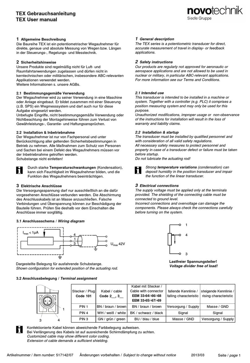
3.1 Anschlussschema / Wiring diagram
1 General description
The T/TR series is a potentiometric transducer for direct,
accurate measurement of travel in display- or feedback
applications.
2Safety instructions
Our products are regularly not approved for aeronautic or
aerospace applications and are not allowed to be used in
nuclear or military, in particular ABC-relevant applications.
For more information see our Terms and Conditions.
2.1 Intended conditions of use
The transducer is intended to be installed in a machine or
system. Together with a controller (e.g. PLC) it comprises
a position measuring system and may only be used for
this purpose.
Unauthorized modifications, improper usage or non-observance
of the instructions for installation will result in the loss of
warranty and liability claims.
2.2 Installation & startup
The transducer must be installed by qualified personnel in
consideration of all relevant safety regulations.
All necessary safety measures to protect personnel and property
in case of a transducer defect or failure must be taken before
startup.
Do not exceed the mechanical adjusting range
(dimension B, see data sheet)!
Do not lubricate the actuating rod!
The attack strength in mechanical end position of the
TR/TRS series may not exceed 5 N!
3Electrical connection
The supply voltage must be applied only at the terminals
provided. The shielding of the connecting cable must be
connected to ground level.
Incorrect connections and overvoltage can damage the
components. Please always check the connections carefully
before turning on the system.
2
1
3 Umax 42V
Imax <1µA
3
2
1 Lastfreier Spannungsteiler
(Ie ≤ 1 μA)
Voltage divider free of load
(Ie ≤ 1 μA)
Seite / page 1
3.2 Anschlussbelegung / Terminal assignment
5 1
4 2
3
Dargestellte Belegung für ausfahrende Schubstange
Shown configuration while extending the rod
TS/TRS
-____-
101
Stecker M8
Plug M8
TS/TRS
Stecker M16
Plug
M16
T/TR
Kabel
cable
Fallende
Kennlinie
Falling
characteristic
Steigende
Kennlinie
Rising
characteristic
Pin
3
Pin
1
BN
braun
/ brown
Anschluss 1: Versorgung
Ub
Connection 1
: Supply
Anschluss 1: GND
Connection 1: GND
Pin
4
Pin
2
RD
rot
/ red
Anschluss 2: Signalausgang
Connection 2: Signal
output
Anschluss 2: Signalausgang
Connection 2: Signal
output
Pin
1
Pin
3
OG
orange
/ orange
Anschluss 3: GND
Connection 3: GND
Anschluss 3: Versorgung
Ub
Connection 3
: Supply
-
Pin 4
-
nicht anschließen /
do not connect
-
Pin 5
-
nicht anschließen /
do not connect
Stecker M16 5-pol.
Plug M16 5-pin
Stecker M8 3-pol.
Plug M8 3-pin
1 3
4
T/TS/TR/TRS Gebrauchsanleitung
T/TS/TR/TRS Manual
4Ausführungen / Models
4.1 Wegaufnehmer / Transducer
Im Lieferumfang enthalten: 2x Spannklammern; 4x Zylinderschrauben M4x10; 1x Kugelkupplung
Included in delivery: 2x mounting clamps; 4x head cap screws M4x10; 1x ball coupling
4.2 Wegtaster / Transducer with return spring
Im Lieferumfang enthalten: 2x Spannklammern; 4x Zylinderschrauben M4x10; 1x Tastspitze mit eingepresster Hartmetallkugel
Included in delivery: 2x mounting clamps; 4x head cap screws M4x10; 1x probe tip with hardened ball point
max. 140Ncm
Seite / page 2
Konfektionierte Kabel können abweichende
Farbbelegung aufweisen.
Bei Verlängerung des Kabels ist auf ausreichende
Schirmdämpfung zu achten.
Customized cable may show different color coding.
Extension of cable demands a sufficient shielding.
In Anwendungen mit starker Vibrationsbelastung wird
empfohlen, die Tastspitze zusätzlich zu sichern (z.B.
kleben).
Bei Tausch oder Demontage der Tastspitze muss die
Schubstange in geeigneter Weise fixiert werden, um ein
Verdrehen oder Verkratzen der Schubstange zu
vermeiden.
Der Bereich für den Kabelabgang muss ausreichend
dimensioniert werden, der Mindestbiegeradius
(r = 28 mm fest / 51 mm bewegt) ist einzuhalten und
scharfe Kanten sind zu vermeiden!
In applications with high vibration load, the probe tip
should be additionally secured (e.g. glued).
When exchanging or dismounting the probe tip, the
push rod must be held in a suitable manner to avoid
twisting or scratching of the rod.
For the area of the cable please take care that
enough space is available, the minimum bending
radius (r = 28 mm fixed / 51 mm moved ) has been
observed and sharp edges have be avoided!
TRS-___-101 (Stecker M8 / Plug M8)
TRS-___ (Stecker M16 / Plug M16)TR-___ (Kabelverbindung / Cable connection)
TS-___ (Stecker M16 / Plug M16)
TS-___-101 (Stecker M8 / Plug M8)
T-___ (Kabelverbindung / Cable connection)
P/N 403002747/00 Änderungen vorbehalten / Subject to change without notice 2020/06
5 Produktidentifikation / Product Identification
Typenschild
Name plate Bestellbezeichnung / Ordering designation
Seriennummer bestehend aus
Fertigungscharge/fortlaufende Nr.
Serial No. consisting of
Batch No./consecutive number
Art.Nr. / Part number

This manual suits for next models

3

Other novotechnik Transducer manuals

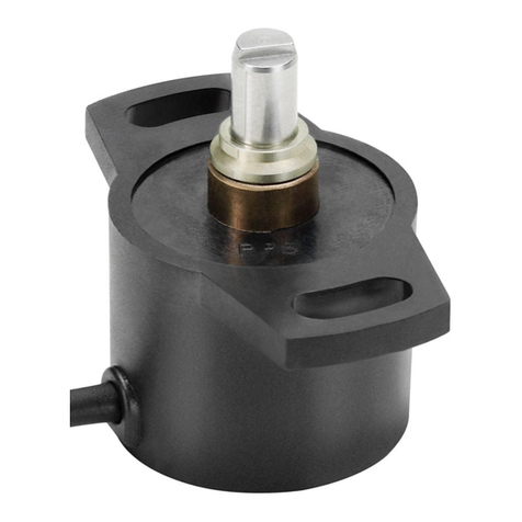
novotechnik TX2 Series User manual

novotechnik

novotechnik TX2 Series User manual

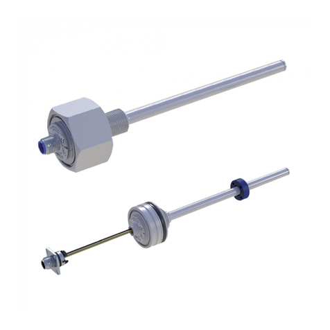
novotechnik TLH User manual

novotechnik

novotechnik TLH User manual

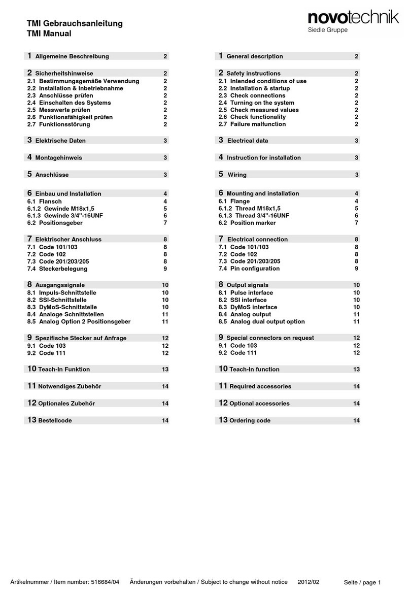
novotechnik TMI Series User manual

novotechnik

novotechnik TMI Series User manual

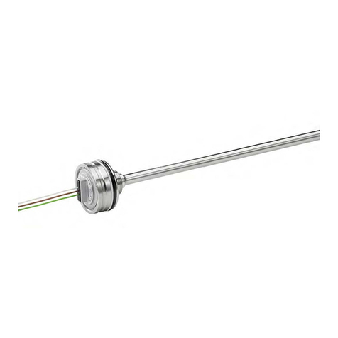
novotechnik Z-TF1-PO1 User manual

novotechnik

novotechnik Z-TF1-PO1 User manual

novotechnik TH1 CANopen User manual

novotechnik

novotechnik TH1 CANopen User manual

novotechnik PTP Series User manual

novotechnik

novotechnik PTP Series User manual

novotechnik LS1 Series User manual

novotechnik

novotechnik LS1 Series User manual

novotechnik LWG Series User manual

novotechnik

novotechnik LWG Series User manual

novotechnik RSM-2800 User manual

novotechnik

novotechnik RSM-2800 User manual

novotechnik RSM-2800 User manual

novotechnik

novotechnik RSM-2800 User manual

novotechnik RFC-4800 CAN User manual

novotechnik

novotechnik RFC-4800 CAN User manual

novotechnik TLM 102 Series User manual

novotechnik

novotechnik TLM 102 Series User manual

novotechnik TP1 Series User manual

novotechnik

novotechnik TP1 Series User manual

novotechnik TIM Series User manual

novotechnik

novotechnik TIM Series User manual

novotechnik TH1 Series User manual

novotechnik

novotechnik TH1 Series User manual

novotechnik TEX Series User manual

novotechnik

novotechnik TEX Series User manual

novotechnik LWX Series User manual

novotechnik

novotechnik LWX Series User manual

novotechnik TM1 Series User manual

novotechnik

novotechnik TM1 Series User manual

novotechnik RSC-2800 User manual

novotechnik

novotechnik RSC-2800 User manual

novotechnik TIM Series User manual

novotechnik

novotechnik TIM Series User manual

novotechnik TM1 Series User manual

novotechnik

novotechnik TM1 Series User manual

novotechnik TH1 Series User manual

novotechnik

novotechnik TH1 Series User manual

Popular Transducer manuals by other brands

Motorola solutions PMLR6833 user guide

Motorola solutions

Motorola solutions PMLR6833 user guide

Minebea TMHS-NM Series instruction manual

Minebea

Minebea TMHS-NM Series instruction manual

Ningbo KPT-G1210 manual

Ningbo

Ningbo KPT-G1210 manual

Balluff BTL6-V11V-M Series user guide

Balluff

Balluff BTL6-V11V-M Series user guide

SOLIDDRIVE SD1 Installation & use guide

SOLIDDRIVE

SOLIDDRIVE SD1 Installation & use guide

Simrad ES120-7C -  REV D datasheet

Simrad

Simrad ES120-7C - REV D datasheet

Balluff BTL6-U110-M****-PF-S4 series user guide

Balluff

Balluff BTL6-U110-M****-PF-S4 series user guide

GP:50 216/316 installation manual

GP:50

GP:50 216/316 installation manual

MKS 901P Short form manual

MKS

MKS 901P Short form manual

Camille Bauer SIRAX BT5200 operating instructions

Camille Bauer

Camille Bauer SIRAX BT5200 operating instructions

Camille Bauer SINEAX U 543 operating instructions

Camille Bauer

Camille Bauer SINEAX U 543 operating instructions

halstrup-walcher PIZ instruction manual

halstrup-walcher

halstrup-walcher PIZ instruction manual

Motorola PMLN6766 manual

Motorola

Motorola PMLN6766 manual

Balluff MICROPULSE Series user guide

Balluff

Balluff MICROPULSE Series user guide

Thinkrace VT460 user manual

Thinkrace

Thinkrace VT460 user manual

Endress+Hauser Cerabar T PMP135 operating instructions

Endress+Hauser

Endress+Hauser Cerabar T PMP135 operating instructions

Beck 984A manual

Beck

Beck 984A manual

Dossena FL Series quick start guide

Dossena

Dossena FL Series quick start guide

manuals.online logo
manuals.online logoBrands
  • About & Mission
  • Contact us
  • Privacy Policy
  • Terms and Conditions

Copyright 2025 Manuals.Online. All Rights Reserved.