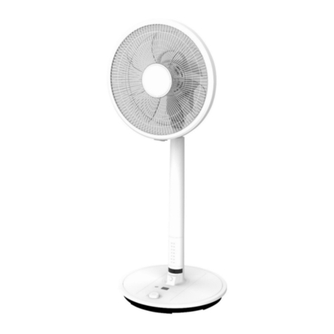
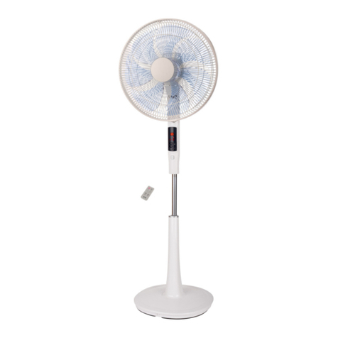
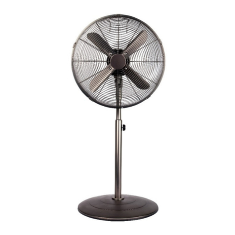
Pillar Base
Operation
1. Control the angle of the airflow by firmly holding the pillar in one hand and pushing
the fan grille bac to tilt up or by pushing it forward to tilt down. Do not adjust the
angle of the fan head when the fan is in motion.
2. Plug into an electrical power soc et and switch on.
3. Choose the desired speed on the rotary control switch 1 = LOW, 2 = MED or 3 = HIGH.
0 = Off.
4. To ma e the fan oscillate, push down on the oscillating nob (12) located on the top
of the motor housing. To stop the fan from oscillating, pull up on the oscillating nob.
Assembly
1. When all components are unwrapped, feed the power cord (16) through the base
plate (15).
2. Insert the pillar base (18) into the base plate (15) and clic into place. Secure with
the clips.
3. Remove the blade cap (5) from the motor housing by turning cloc wise and the
clamping nut (7) by turning anti-cloc wise.
4. Install the rear grille (8) by positioning onto the three pins on the front motor cover
(10).
5. Secure in place with the clamping nut (7) by turning cloc wise.
6. Insert the blade (6) onto the motor shaft (9), matching the slot on the bac of the
blade with the shaft pin.
7. Secure blade with blade cap (5), turning anti-cloc wise to tighten.
8. Test blade operation by rotating it with your hand. There should be no friction with
the clamping nut or the rear grille. If blade does not rotate freely, repeat steps 4 to 8.
9. Open the safety screw (3) and securing clip (4) on the guard ring (1). Keep screw
safe.
10. Hoo front grille (2) onto bac grille (8) from the top and clic guard ring into place.
11. Close securing clip, replace and tighten safety screw with screwdriver.
BS plug wiring
Wiring instructions: Should it be necessary to change the plug please note the wires in
the mains lead are coloured in accordance with the following code:
BLUE – NEUTRAL :: BROWN - LIVE
As the colours of the wires in the mains lead of this appliance may not correspond with
the coloured mar ings identifying the terminals in your plug, proceed as follows:
1. The BLUE wire is the NEUTRAL and must
be connected to the terminal which is
mar ed with the letter N or coloured
BLACK.
2. The BROWN wire is the LIVE and must be
connected to the terminal which is
mar ed with the letter L or coloured RED.
3. NEITHER WIRE must be connected to the
terminal which is mar ed with the letter E,
the symbol , coloured GREEN or
GREEN/YELLOW.
4. Always ensure that the cord grip is
positioned and fastened correctly.
If a 13A (BS 1363) fused plug is used it must be fitted with a 3A (BS 1362) fuse. If in doubt
consult a qualified electrician.


