NSK Varios 970 User manual

OPERATION MANUAL
Please read this Operation Manual carefully before use,
and file for future reference.
OM-E0847E 000
Multi Function Ultrasonic Scaler
Varios 970
2018.11.29 002 N

1
English
1. Cautions for handling and operation
Read these cautions carefully and use only as intended or instructed.
Safety instructions are intended to avoid potential hazards that could result in personal injury or damage to the device.
Safety instructions are classified as follows in accordance with the seriousness of the risk.
• TO PREVENT ELECTRIC SHOCK Do not unplug the power cord with wet hands.
• TO PREVENT ELECTRIC SHOCK Be sure to prevent water on the Control Unit.
• TO PREVENT ELECTRIC SHOCK Do not touch the handpiece backend electrical connections.
• TO PREVENT ELECTRIC SHOCK Use an electrical outlet that is grounded.
• If you feel any abnormality such as vibration, heat generation, abnormal noise, etc., prior or during the use of the unit, stop
using it immediately.
• Do not turn the Power Switch without reason; it might blow out a fuse.
• This product is Medical Electrical equipment Electromagetic compatable (EMC).As described in the accompanying
documentation.
• Portable and mobile RF communications equipment can affect Electrical Medical equipment. Do not use RF equipment in
close proximity to the product.
• When installing the product, provide space of approximately 10cm around the Control Unit for easy access to the inlet and
the Power Cord.
• When operating the product always consider the safety of the patient.
• Use by medical professional, such as doctor or dental hygienist, is intended.
• Check the vibration outside the patient’s oral cavity before use. If any abnormalities are found, stop using immediately and
contact your dealer.
• Do not drop, hit, or subject to excessive shock to the Control Unit/Handpiece.
WARNING
Classifications of equipment
• Type of protection against electric shock:
– Class I equipment
• Degree of protection against electric shock:
– Type BF applied part:
• Method of sterilization or disinfection recommended by the manufacture:
– See 12. Sterilization
• Degree of protection against ingress of water as detailed in the current edition of IEC 60529:
– Foot Control: IPX1 (Protected against vertically falling water drops)
• Degree of safety of application in the presence of a flammable anesthetic mixture with air or with oxygen or nitrous oxide:
– EQUIPMENT not suitable for use in the presence of a flammable anesthetic mixture with air or with oxygen or nitrous
oxide.
• Mode of operation:
– Continuous operation
Intended to Use
This product is designed only for dental clinic /dental office use. This device generates ultrasonic waves intended for use in
dental applications such as scaling, root canal treatment, periodontal and cavity preparation.
Class Degree of Risk
WARNING A hazard that could result in bodily injury or damage to the device if the safety instructions are not
followed.
CAUTION A hazard that could result in light or moderate bodily injury or damage to the device if the safety
instructions are not followed.
NOTICE General information needed to operate the device safely.

2
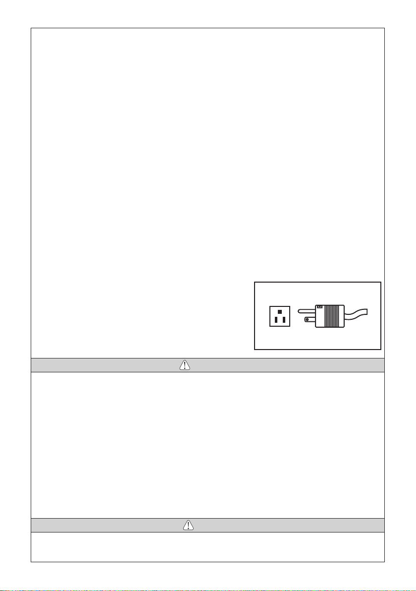
Power plug below is used in North America area.
Plug Type NEMA 5-15P (Hospital Grade Type)
• USE ONLY NSK genuine tips when using NSK Varios Ultrasonic Scaler (Varios 970 or Varios 970 LUX) problems such as
damage, failure and accident of Handpieces resulting from use of Non-NSK Tips are not included in the warranty. The
following are the possible failure that could happen when using the Non-NSK Tips;
· Vibration failure caused by using non conforming screws.
· Patients accidental ingestion of broken tips.
· Damage of thread ridge of handpiece.
· You must use the tip within the power range described on the Tip-Power Guide. If you use it out of the power
range, the tip might break or damage an operative site.
• To prevent possible tooth plane damage and handpiece overheating, Always use with sufficient water.
• Do not sterilize by ultraviolet light. Handpiece could discolor.
• Sterilize the Tip, Handpiece, and Tip Wrench by autoclaving. Wipe the Control Unit, AC Power Cord, Foot Control, and
Handpiece Cord including the cover.
• If chemical, solvent or antiseptic solution is deposited on this product, immediately wipe it away. Discoloration or
deformation may occur if left.
• Do not disassemble or alter the handpiece/Control Unit.
• Keep away from patients with cardiac pacemakers.
• Keep away from explosive substances and flammable materials. Do not use for patients anesthetized under laughter gas.
(Nitrous Oxide)
• Use the Fuse of specified rating. (120V: T630mAL 250V, 230V: T315mAL 250V)
• This product needs special precautions regarding EMC and needs to be installed and put into service according to the
EMC information.
• The use of ACCESSORIES, transducers and cables other than those specified, with the exception of transducers and
cables sold by the manufacturer of this product as replacement parts for internal components, may result in increased
EMISSIONS or decreased IMMUNITY of this product.
• This product should not be used adjacent to or stacked with other equipment and that if adjacent or stacked use is
necessary, this product should be observed to verify normal operation in the configuration in which it will be used.
• If any water drops remain on the handpiece after autoclaving, wipe them
off., Staining may result if left.
• There is the judgment that applies this product to a patient in the user side.
• Grounding reliability can only be achieved when the equipment is
connected to an equipment receptacle marked "Hospital Only" or "Hospital
Grade".
• Do not apply excessive power to the Tip. It may damage the teeth because
of the ultrasonic vibration.
• During operation, high frequency oscillations in the handpiece and handpiece cord may affect computer and LAN Noise
may be heard during operation near a radio receiver.
• Be sure to turn off the Power Switch after use. Remove the power plug and water inside of the Control Unit before storage.
• Users are responsible for operational control, maintenance and inspection.
• Clean/sterilize the product immediately after using it. Then store it. Leaving it non-sterile might lead to failure.
• When cleaning, use MinutenWipes (ALPRO) to wipe the surface of the handpiece. Use of chemicals other than those may
cause the handpiece to discolor, crack, etc.
• When you have not used the product for long time and use it again, check the operation before use.
• Eye damage may result if the LED is stared directly into, Do not look into or turn it to the eyes of the patient.
• This product does not consider patient’s age (except infants), gender, weight or nationality.
• No special training is required for this device.
• Applied parts for patient and/or operator are/is tip and Handpiece.
• Surface temperature of tip shall be more than 50 degree without using a tap water or bottle. To avoid this event, be sure
to use a tap water or bottle.
• Repeated autoclaving may cause the handpiece to become discolored due to heat. However, this is due to properties of
the product and is not a problem in terms of quality.
CAUTION
NOTICE

English
3
English
2. Component Names
Optic Non-OpticNon-OpticOptic
No. Parts Name Quantity
1Control Unit 1
2VA Bottle 2
3 AC Power Cord 1
4Varios2 Handpiece (Optic or Non-Optic) 1
5Handpiece Cord (Unshielded 2M)
(Optic or Non-Optic) 1
6 Foot Control 1
7 Sterilization Case 1
8Tip Wrench 3
9 Tip G4 1
10 Tip G8 1
11 Tip G16 1
12 O-Ring (Thin section) (For VA Bottle) 2
13 O-Ring (Thick section) (For VA Bottle) 2
14 O-Ring (For Handpiece Cord) 2
15 Water Connector (Option) 1
16 Water Tube (Option) 1
17 Spanner Wrench (5x8) (Option) 2
18 Tip Cover S (Option) 1
19 Tip-Power Guide 1*
20 Tip Card 1*
21 Operation Manual 1*
* Operation Principle
A sinusoidal electrical signal, at ultrasonic frequency ( f > 20Khz ), is delivered by the generator. This signal is applied
to the ‘piezoelectric ceramic’ located inside the transducer. Piezoelectric ceramic converts this signal into mechanical
vibrations. These vibrations are at the same ultrasonic frequency as the electrical signal. The mechanical vibrations
are propagated towards the distal end of the transducer. The “TIP” insert, which is attached at the distal end of the
transducer, vibrates at ultrasonic frequencies and makes it possible to achieve the aimed purpose.
* These are not on photo above.
Option
1
2
3
4
5
11910
15
16
17
18
6
7
8
12 13 14

4
3. Name and Function of each part
Left Bottle (L Bottle) Right Bottle (R Bottle)
* L and R bottle is common
Handpiece Holder
Bottle Selection Indicator R
(Right)
Bottle Selection Indicator L
(Left)
Tap Water Adjustment Knob
Bottle Water Adjustment Knob
<Bottom>
Power Switch
Foot Control Connector Tap Water Connector
AC Power Cord Connection Jack
Handpiece Cord Connector

English
5
English
CAUTION
• Do not turn the knob fast. It may not sense
the movement if it turn fast.
• Water Volume can set during 5ml/min to
45ml/min.
• Operation sound may different between
Right and Left Bottle.
• During adjustment of water volume,
Numerical Display indicate “–”.
If you purchase the Optional products such as Water Tube and Water Connector you can use Tap Water.
Mode Select Keys
You can select Operation Mode to pressing this key. (Perio, Endo and General) The Control Unit can resume power level,
water volume and irrigation mode for each Operation Mode.
Power Level Keys
Press key to select Power o/p Level . There are 11 levels (0 to 10). There
is no output vibration at level 0 (zero). (Fig.1). The Bar Graph Indicator and
Numerical Display will change simultaneously.
Irrigation Select Key
Press key to select ‘R’ or ‘L’ Bottle. Front panel display and Bottle Selection Indicator simultaneously change in position.
Pressing the Irrigation Select Key for more than one second will select Tap Water Mode.
Auto-Cleaning Key
Press key to select Auto Cleaning Mode, For detail refer to 11. (5).
Bottle Water Adjustment Knob
Water Volume Adjustment can be made prior to the tip vibrating
you can adjust the Water Volume during Bottle Irrigation or
during a wait before Tip vibration start. If the setting is not
applicable (too low or too high) for the Control Unit, it may beep.
During the operation, Front Panel displays the current Power
Level. However, keep turning the knob more than a second; it
may change the Water Volume.
Operation Panel and Display
Fig.1
Mode Select Keys Power Level Keys
Endo Key
Perio Key General Key
Down Key
Up Key Irrigation Select Key
Operation Mode
Display
Numerical Display Bar Graph Indicator
Irrigation Mode
Display
Auto-cleaning Key

6
CAUTION
NOTICE
• Use of Tap Water (Option)
1) Remove the Cover from the Tap Water Connector. (Fig. 5)
2) Connect the filter side of the Water Tube deep into the Control Unit Tap Water Connector (Fig. 6).
3) Connect the water tube to the water outlet on the Dental Unit.
4. Prior to Operating System
Tap Water Adjustment Knob
You can adjust tap water volume by this Knob. (Even the tip vibration).
• Use the VA Bottle Set 400 only for Varios 970.
• Before filling solution to the VA Bottle, check the Gasket inside the bottle
cap is clean. (Fig. 4)
• Do not use a sharp tool to clean the Gasket or do not allow any impact
on to the product. It may cause malfunction.
• Insert the Bottle straight. (Damage to seals may result).
• Keep the Gasket clean. When it becomes dirty by water or antiseptic
solution, wash by clean water it immediately.
• The Gasket is consumable. *Optional Gasket: Order Code Z1047350
• The Bottle calibrations are printed on both sides of the Bottle and can be
read accurately from the fill position or mounted on the Control Unit.
• Mount the Dust Cover when not in use.
(1) Water System Setup
• Use of Bottle
1) Remove the Dust Cover from the Bottle Base Connector. (Fig. 2)
2) Remove the cap of the VA Bottle and fill solution to the desired level.
3) Close the cap of VA Bottle and insert the Bottle Joint into the Bottle Base
Connector until it clicks. (Fig. 3)
To remove the Bottle, pull it up.
Fig.5
Cover
Fig.6
Tap Water Connector
Water Filter Case
Water Tube
Fig.2
Dust Cover
Bottle Base Connector
Fig.3
Bottle Joint
Fig.4
Gasket

English
7
NOTICE
CAUTION
CAUTION
• Insert the Water Tube firmly into Control Unit.
•
Pushing the White Ring, (the Quick Connector Release Ring) on
the Tap Water Connector, gently pull the tube to remove. (Fig. 7)
• When the water tube is not connected, mount the cover on the
Tap Water Connector.
Ensure the water from the dental unit runs clear before connecting to the scalar.
(2) Foot Control Connection
Connect Foot Control Plug and the Control Unit with [ ]
mark on the upper surface of the plug. (Fig.8)
(3) Handpiece Cord Connection
Insert Handpiece Cord Plug into Control Unit. [ ] Mark side
is upper surface. Do not insert it up-side-down. (Fig.9)
Check that the Handpiece Cord Plug is clean & dry before connecting. (Fig.10)
Fig.7
White Ring
Fig.8
Foot Control Connector
Foot Control Plug
[ ] Mark
Fig.9
Handpiece Cord Connector
Handpiece Cord Plug
[ ]
Mark
Fig.10

8
CAUTION
WARNING
CAUTION
1) Turn Tip lightly by hand, and install it. (Fig. 13)
2) Tip will insert from the bottom hole of Tip Wrench. Align the four corner of the Tip base area into the four corner of Tip
Wrench. And turn it clockwise until it clicks. (Fig. 14)
Do not touch the top part of Tip to avoid an injury. (There is the case that is longer than height of TIP WRENCH)
To remove the Tip, turn it counterclockwise with the Tip Wrench.
6. Mounting and Removing Tip
(4) Mounting Power Cord
Insert the Power Cord into the AC Power Cord Connection
Jack at the back of the Control Unit. (Fig. 11)
• Ensure Power is OFF on the Control Unit during the Power Cord Connection. It may cause Fuse to blow.
• Do not connect the cord in wall outlet before connecting AC Power Cord.
• Do not pull the AC Power Cord forcibly.
• Do not unplug the Power Cord or handpiece cord while pressing on the Foot Control.
5. Mounting and Removing the Handpiece
Align the Dots on the Handpiece and the Handpiece Cord. Push
handpiece into connector.
To remove the handpiece, grip the Handpiece and Handpiece
Cord and pull to part handpiece and cord. (Fig. 12)
To avoid Electrical Shock Do not touch the handpiece
backend electrical contacts.
• Always confirm that the handpiece is correctly seated and locked into place.
• Do not connect or use Handpiece other than included one (Varios2 handpiece).
Fig.11
AC Power Cord Connection Jack
Power Cord
Fig.14
Loosen Tighten
Tip Wrench
Tighten
Loosen
Fig.12
Dots
Handpiece backendHandpiece Handpiece Cord
Fig.13

English
9
Caution for Tip Usage
CAUTION
• Check the Tip before use. (Flush, Damage, Bending or Rust)
• Do not exceed Maximum Power Level for Tip. Damage to tooth structure and Tip may result.
• Do not hit ceramic prosthesis with Tip during scaling. Tip Damage may result.
• Do not hit metal or prosthetic crown except for removing them. Tip could break and fall into mouth.
• Do not hit gingival, mucosa and/or skin. It could cause damage and/or burn injury.
• Do not sharpen and/or bend the Tip. Tip may damage and not generate enough vibration during scaling.
• During cutting, Tip will gradually wear away, as the Tip wears the stroke will get smaller and decrease cutting
efficiancy When level drops too far, change the Tip.(tip card check)
• DO ENSURE When securing tip to use the tip wrench as supplied, inefficient cutting will result.
• DO ENSURE before attaching Tip, Cleanliness of the tip screw, inefficient cutting will result.
• To avid personal injury DO ENSURE tip is removed prior to disconnecting the handpiece or the handpiece cord.
• If you feel the Tip is not vibrating, remove it from an operative site, and press the Foot Control again. If this does
not improve the condition, Ensure the tip is secure, turn the power off and restart it.
• When mounting the Tip, always use groves and Tip Wrench as supplied.
• Ensure that water volume must be “0”, when you use Tip which does not appear of water.
• Tip Wrench is consumable For reliable operation replace annually.
7. Operating Procedures
(1) Water System Setup
• Use of Bottle
1) Check that the VA Bottle is filled to the proper level.
2) Make sure that the cap of the Bottle is secure and not leaking.
• DO ENSURE liquid temperature is below 35°C.
• Do not put liquid such as high acid water in the Bottle.
(2) Power On
Connect the AC Power Cord to the wall outlet. Turn the Power
Switch on the Control Unit. Front Display will illuminate.
• Use of Tap Water
1) Ensure water tube is firmly connected.
2) Open the dental unit's water valve. (Set water pressure between 0.1-0.5MPa (1-5 kgf/cm2)).
Fig.15
Power Switch

10
NOTICE
(3) Power Level Setting
DO ENSURE Power setting does not exceed the recommended Power Level (Tip-Power Guide included in the package.)
1) Select the Operating Mode with the Mode Select Keys on the Front Panel. The Indicator light over the selected mode
will illuminate. (Fig. 16)
• Press & Hold the Power Level Key will increase or
decrease the Power Level.
• If the Power Level is 0 (zero) and set the water
volume, Tip will not oscillate but water comes out
from the handpiece.
2) Set the power level with the Power Level Key on the
Front Panel. The Bar Graph Indicator and Numerical
Display will indicate the selected power level. (Fig. 17)
Make sure the power level is set in the appropriate
range for the attached Tip.
(4) Irrigation setting
Select the Irrigation Mode (L Bottle, R Bottle or Tap Water) with
the Irrigation Select Key on the Front Panel. (Fig. 18)
The Indicator light over the selected mode will illuminate.
Press & Hold the Irrigation Select Key to select Tap Water Mode.
(5) Operate Varios 970 / 970 LUX
By stepping on the Foot Control, the tip vibrates and spraying
starts (except for tips that do not spray) and the handpiece
LED lamp lights up (Varios 970 LUX).
When you remove your foot from the foot control, tip vibration
and water spraying stop and the handpiece LED lamp turns
off. (Varios 970 LUX).
• Water Supply Volume Adjustment
Turn the Water Adjustment Knob counterclockwise gradually
to increase the supply volume. (Fig. 19) For detail, refer to P5
Bottle Water Adjustment Knob or P6 Tap Water Adjustment
Knob.
Fig.19
Increase
Mode Select Keys
Operating Mode Display
Power Level for each mode
Fig.16 Power Level Key
Bar Graph IndicatorNumerical Display Fig.17
Fig.18
Irrigation Select Key
L Bottle Tap Water R Bottle
Increase
Tap Water Adjustment Knob Bottle Water Adjustment Knob

English
11
CAUTION
NOTICE
CAUTION
(6) After the treatment
Release the Foot Control and Power off the Control Unit.
• Use of Bottle
Thoroughly wash the Bottle (s) Water Supply system. Refer to 11. (5) Auto Cleaning (Cleaning of Irrigation Tube).
• While pressing the Foot Control and switching the power ‘ON’. The Control Unit will display "F" and sound a beep,
for your safety the Control Unit will not operate. Remove your foot from Foot Control to cancel and reset.
• Bar Graph Display (Fig.20)
Minimum Irrigation -> One white and blue LED.
No Irrigation -> Blue LED only
• Always use the water supply. If water supply is
insufficient, handpiece will overheat and patient’s
tooth surface can be injured.
• Verify that the water spray is clean and of
adequate volume before use.
• If irrigation volume set low, sometimes irrigation water is difficult to come out from the Tip.
When it happened, set volume again after setting up high volume.
• During Water Adjustment Knob operation;
Numerical Display: Display "-"
Bar Graph: Display current volume of water
• LED of the handpiece will remain ‘On’ for approx 5 seconds after Foot Control is released. (Varios 970 LUX)
• When the Control Unit is Power off, the last mode settings in use are automatically retained in memory.
When using medicated solutions, clean the entire Irrigation System thoroughly.
Initialized Program (Factory Setting)
Press both Auto-Cleaning and Power Key on the Control Unit to initialize the Factory memory Setting. Do not release
Auto-Cleaning Key until the beeping sound from the Control Unit. (Initial Mode is Perio)
During the Handpiece operation :
Possible: Power Level and Water Volume adjustment.
Impossible: Operation Mode and Irrigation Mode setting, Auto Cleaning.
Power Flow amount (L, R each) Irrigation Mode Initial Mode
Perio 110 L Bottle
Endo 110 L Bottle
General 1 10 L Bottle
• Use of Tap Water
Close the dental unit's water valve.
Fig.20
Minimum irrigation No Irrigation

12
CAUTION
8. Provided Scaler Tips
The end of the Tip is thin and for supragingival fine scaling and interdental scaling. The
round cross-section allows tooth surfaces to be finished without causing damage.
Tip is article of consumption. We recommend periodical replacement. About time of replacement, check the Tip
Card.
G4
Apply the top of the Tip on the tooth plane and move it sideways
finely in the same way as G8 Tip. (Fig. 21)
Removal of supra and subgingival calculus. It provides easy access to interdental
spaces and narrow pockets.
G16
Insert the top of the Tip into the periodontal pocket and move it
slowly. The top of the Tip is sharp so that it could remove tartar
on long coroner and retracted gingival. (Fig. 23)
Clean periodontal pocket at low power.
Removal of supragingival and interdental calculus. This Tip can be used in all
quadrants and is very useful for the removal of hard calculus.
G8
Apply the top of the Tip on the tooth plane and move it sideways
finely along the neck of tooth. (Fig. 22)
Fig.21
Fig.23
Fig.22

English
13
WARNING
CAUTION
Fig.26
Do not connect the supplied G16 Tip to a handpiece
other than a Varios2 handpiece (VA2-LUX-HP /
VA2-HP). Doing so may cause fracturing of the Tip or
scratches on the surface of the dentition, prosthesis,
etc. due to an increase in vibration amplitude (Fig. 24).
How to use the Tip Card
1) Place the neck of the Tip in the cut out.
2) Check wear of the Tip.
3) See the green, yellow and red line to check wear of the Tip. *See below what each color means. At NSK we recommend
to replace a Tip when the Tip meets the yellow line (wear of 1mm) to guarantee safe and effective use.
Tips are consumables. The efficiency of dental scaling
decreases approximately 25% when the top of the Tip
wears 1 mm and approximately 50% when it wears 2 mm.
In addition, the vibration condition changes owing to the
wear, which may damage a patient’s tooth surface. Check
the Tip wear condition with the Tip Card periodically, and
replace the Tip with a new one in good time.
1mm 2mm
25%
Decrease 50%
Decrease
Efficiency
Fig.25
Tip Card
Green: No wear - Tip is OK
Tip replacement is not necessary.
Yellow: Wear of 1mm - Tip is showing some wear
Tip replacement is recommended.
Red: Wear of 2mm - Tip is badly worn
Tip replacement is necessary.
Fig.24

14
CAUTION
CAUTION
CAUTION
NOTICE
9. How to Use Tip Cover S (Option)
Grip the Tip Cover S and insert it to the Tip.
To remove, grip the Tip Cover S and the handpiece & pull. (Fig. 27)
The Tip Cover S is not designed for use as a Tip changing tool.
Carefully insert the Tip
into the Tip Cover S. Avoid
injuring the fingers.
10. Handpiece Holder
While the Handpiece is not in use, put the Handpiece in the
Handpiece Holder.
The Handpiece Holder is adjustable. (Fig. 28)
11. Care and Maintenance
(1) Cleaning of Optic Fiber (Varios 970 LUX)
Wipe the debris off the end of the Optic Fibers at the
handpiece with alcohol soaked cotton swab. (Fig. 29)
Do not use any sharp pointed tools to clean the
Optic Fiber End Face. In case the light degridation,
contact your dealer.
Do not put excessive load to the Handpiece Holder
to prevent from breaking down and deformation.
To prevent injury, always mount Scaler Tip Cover (S).
Fig.27
Slit
Slit
Tip
Tip Cover
Tip-Handpiece Joint
Fig.28
Handpiece Holder
Fig.29
Optic Fiber End Face

English
15
Fig.32
CAUTION
(3) Changing O-Ring
• Handpiece Cord
An O-Ring is located in the Handpiece Cord Connector. Use a pointed tool to remove,
and mount new O-Ring into the groove. (Fig. 31)
* Optional O-Ring: Order Code D0310020080
• VA Bottle
Remove two O-Rings at the Bottle Joint with a pointed tool, and
mount new O-Rings into the grooves. (Fig. 32)
* O-Ring (Thick section) : Order code D0310075150
O-Ring (Thin section) : Order code D0312090100
(4) Changing the Irrigation Pump
1) Remove the Bottle, the Power Cord, the Handpiece Cord and the
Foot Control from the Control Unit.
2) Turn back the Control Unit. Hang a finger on “ ” point and pull
up the bottom cover to remove.
(2) Cleaning the Handpiece cord
Remove the handpiece after use on each patient and clean it
as described below.
1) Wipe the surface of the handpiece cord with a cloth soaked
in alcohol.
2) Carefully wipe the handpiece cord plug with an
alcohol-immersed cotton swab. If it is difficult to use a
cotton swab, carefully wipe with a towelette wound around
a thin stick-shaped object.
Do not use a sharp pointed stick or push the terminal part when cleaning the handpiece cord plug. Doing so may
cause damage, resulting in contact failure (Fig. 30).
Fig.31
O-Ring
Fig.33
Fig.30
Terminal part
O-Ring (Thick section)
O-Ring (Thin section)

16
Fig.35
* Bottle side
Fig.36
* Front Panel side
Fig.39
* Front Panel side
3) Remove the Irrigation Tube from the Control Unit. (Bottle side and Front Panel side.) (Fig. 35, 36)
4) Remove the Connector Ring from the Irrigation Tube. Do not dispose it. You can use the Rings to the replacement
Irrigation Pump.
5) Turn the Irrigation Pump counterclockwise until it clicks
and pull it out. (Fig. 37)
6) Mount the Connector Ring to the new Irrigation Pump.
Observing Ring direction. (Fig. 38)
7) Align the replacement Irrigation Pump with the Drive Shaft.
Turn clockwise until it clicks. (Fig. 37)
8) Mount the Irrigation Tube opposite procedure of removing
(Fig.35). Connector Ring should firmly into the Control Unit
until it stops. (Fig.39)
Picture below is shows inside of the Control Unit.
Fig.34
Bottom Cover (Back Side)
Bottom Cover Hook
R Bottle Bottle Joint
Front Panel Side
L Bottle Bottle Joint
R Pump Tube Joint
L Pump Tube Joint
R PumpL Pump
Irrigation Tube
Fig.37
Irrigation Pump
Irrigation Tube
Connector Ring
Remove
Mount
Remove
Mount
Irrigation Tube
Connector Ring
Irrigation Tube
Release LockRelease Lock
Irrigation Pump
Connector RingConnector Ring
Fig.38
L/R Pump side
Irrigation Tube
Control Unit side
Connector Ring

English
17
CAUTION
NOTICE
NOTICE
CAUTION
CAUTION
• If water is spilled out the irrigation pump, wipe it off and allow drying completely prior to use. If water gets inside
the irrigation pump the roller may slip and fail to pump.
• Before replacing the Irrigation Pump, wipe off excess water on pump and Drive Shaft. The wet drive shaft and
rollers can be slippery and cause improper operation.
• Wipe dirt and water off the Drive Shaft from bottom up.
(Fig.40)
• Insert the replacement Irrigation Pump into the Drive
Shaft straight (slow and soft) to prevent damaging rollers
in pump.
• Run the replaced Irrigation Pump about 10 seconds
on largest setting of Water Volume before operation to
adopt Irrigation Tube to new pump.
• Ensure Irrigation tube has no kink or twists If tube is set
incorrectly, Irrigation Water may not come out.
• Do not pull the tube when the bottom cover is closed.
• Perform periodical cleaning for the Drive Shaft with socked alcohol cloth. Dirt on Drive Shaft may cause an
incorrect pump operation.
• The pump is consumable. If the irrigation volume decreases markedly, replace pump.
9) Align the Bottom Cover Hook and hole on the Control Unit. Mount the Bottom Cover.
* Optional Irrigation Pump: Order Code 10000643 (Not included the Connecter Ring.)
(5) Auto Cleaning (Cleaning of Irrigation Tube (Use of Bottle))
1) Remove the 2 Bottles from the Control Unit.
2) Clean inside of the Bottle.
3) Half fill the bottle with purified water (DO NOT USE SALINE)
• After each use, remove all the disinfectant solution and perform "Auto Cleaning" procedure. If you have not
cleaned the system, it may become dirt disinfectant. And it is stuck in the tubing or some of the metal parts may
be rusted.
• During Auto Cleaning, water comes out from the handpiece. Perform cleaning after turning handpiece into a cup.
• Perform Auto-Cleaning without tip.
• Make sure the handpiece and handpiece cord are firmly attached.
Use only distilled water for cleaning.
4) Install the cap on the Bottle. Install the Bottle Joint into the Bottle Base Connector. Install it until clicks into place.
Improper connection may cause water leakage. Make sure the connection is tight.
Fig.40
Drive ShaftDrive Shaft

18
NOTICE
NOTICE
5) To perform the Auto-Cleaning, keep pressing the Auto-Cleaning Key (more than 1 second).It takes 30 seconds per
bottle to clean The Numerical Display will alternately displays “A” and “C”, the Bar Graph displays time remaining.
Single display (Bar Graph Display) is 6 second. When five displays of Bar Graph disappeared, Bottle will be changing
the other side.
To cancel the Auto-Cleaning, press Auto-Cleaning Key again.
The Control Unit does not perform in Auto-Cleaning in Tap Water.
During Auto-Cleaning, LED of the handpiece
does not illuminate. (Varios 970 LUX)
6) When the Auto-Cleaning is finished, the Control Unit returns to the settings prior to cleaning. Remove the both bottles
from the Control Unit by pulling straight up. Clean thoroughly rinse and dry.
Following method is also available for cleaning. (Manual Cleaning)
1) Remove the Bottle from the Control Unit.
2) Open the cap of the cleaned Bottle and fill it with distilled water.
3) Close the cap firmly and insert the Bottle Joint into the Bottle Base Connector on the Control Unit until it clicks.
4) Operate the Control Unit about 30 seconds with water supply at maximum setting.
(6) Changing Water Filter (Option)
If you use Tap Water, change the Water Filter as it may necessary.
1) Close the water valve of the dental unit.
2) Mount two Spanner Wrenches (5x8) and turn those as shown in Fig.42.
3) When the Water Filter case is separated, the Water Filter can be removed as shown in Fig.43.
4) Replace with new ( Order Code U387042 ) and reassemble the filter in the reverse order.
Fig.41
Auto-Cleaning Key
Numerical Display Bar Graph
Fig.42
Water Filter Case
Fig.43
O-Ring
Water Filter
Varios970/Varios970 LUX Dental Unit
Dental Unit
Varios970/
Varios970 LUX

English
19
NOTICE
CAUTION
Only handpiece can be washed via Thermo Disinfector.
Repeated autoclaving may cause the handpiece to become discolored due to heat. However, this is due to
properties of the product and is not a problem in terms of quality.
• Do not sterilize by ultraviolet ray. The handpiece could discolor.
• If autoclaved with other instruments stained with chemical solution, it could strip the plating and make the surface
black.
• Do not autoclave any parts (the Control Unit, Power Cord, Bottle, Foot Control, Handpiece Cord, O-Ring). Other
than those that can be subjected to autoclave sterilization. Perform alcohol disinfection to the Control Unit, Power
Cord, Foot Control, Handpiece Cord including after every patient.
• Do not wipe with, or clean or immerse in, high acid water or sterilizing solutions.
12. Sterilization
• Autoclave sterilization is recommended.
• Autoclave sterilization required first time you use and after each patient as noted below. Take handpiece out of the
packing bag before sterilization.
• ONLY the Tip, Handpiece and Tip Wrench can be autoclaved.
Autoclave Procedure
1) Remove the Tip after use. (Refer to 6. Mounting and Removing Tip)
2)
Wipe dirt and debris from the products, and wipe clean with alcohol-immersed cotton swab or cloth. For handpiece, use
MinutenWipes (ALPRO) to wipe. Do not use a wire brush.
3) Insert those into the Sterilization Case or an autoclave pouch. Seal the pouch.
4) Autoclavable up to max. 135˚C.
Ex.) Autoclave for 20 min. at 121˚C, or 15 min. at 132˚C.
5) Keep the products in the Sterilization Case or autoclave pouch to keep it clean until you use it.
* Sterilization at 121°C for more than 15 minutes is recommended by ISO17664 and EN ISO17665-1.
Sterilization Case
The Handpiece, Tip and Tip Wrench can be sterilized together using
Sterilization Case.
1) Remove the Tip after use. (Refer to 6. Mounting and Removing Tip)
2) Set the Tip Wrench with Tip into the Sterilization Case. (You can set four
Tip Wrenches and Tips at once).
3) Remove handpiece from the Handpiece Cord, and clean.
4) Set the handpiece into the Sterilization Case.
5) Autoclavable up to max. 135˚C.
ex.) Autoclave for 20 min. at 121˚C, or 15 min. at 132˚C.
6) Keep the products in the Sterilization Case or autoclave pouch to keep it clean until you use it.
Fig.44
Other manuals for Varios 970
1
Table of contents
Languages:
Other NSK Dental Equipment manuals