NSK Viva Ace User manual

OM-E0798E 000

1
English
Thank you for purchasing VIVA ace Basic Set.
This product is a Portable Dental Treatment Unit used for on-site patient treatment.
Please read this Operation Manual carefully before use so that you can use it safely to come through a correct use.
Keep this Operation Manual within easy reach of users for future reference.
1. User and Indications for Use.......................................... 2
2.
Precautions for handling and operation
............................... 2
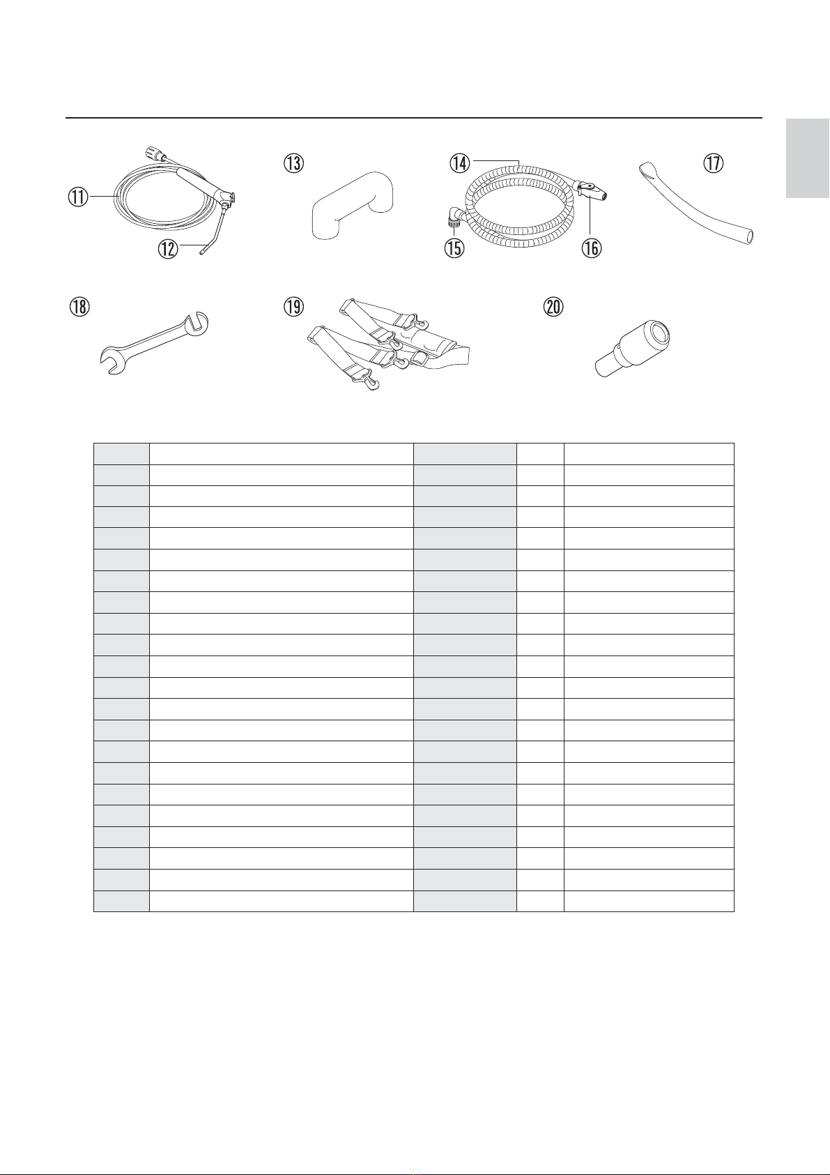
3. Package Contents ......................................................... 6
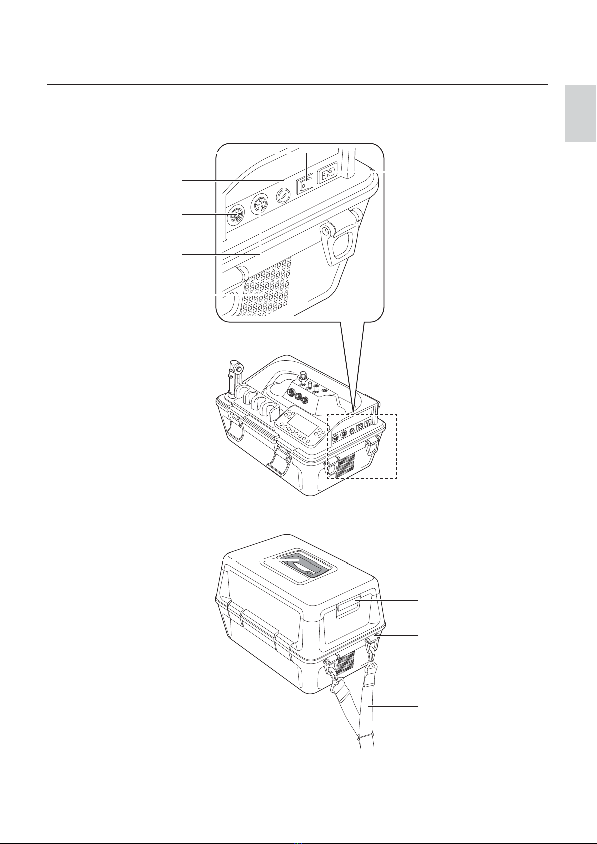
4. Part Names ................................................................... 8
4-1 Control unit .................................................................................8
4-2 Control Panel ............................................................................10
5. Preparation for Use ......................................................12
5-1 Preparation of Control Unit.........................................................12
5-2 Connecting the Syringe .............................................................13
5-3 Connecting the Motor................................................................14
5-4 Connecting the Scaler ...............................................................14
5-5 Installing the Vacuum Bottle.......................................................15
5-6 Installing the Vacuum Hose........................................................16
5-7 Installing the Water Bottle..........................................................16
5-8 Connecting the Foot control.......................................................17
5-9 Connecting the AC Power Cord ..................................................17
5-10 Check before treatment .............................................................18
6. Operation Procedure..............................................................19
6-1 Motor........................................................................................19
6-2 Motor <Endodontic treatment> .................................................20
6-3 Ultrasonic Scaler.......................................................................22
6-4 Vacuum ....................................................................................23
6-5 Light Probe ...............................................................................24
6-6 3way Syringe ............................................................................24
6-7 When the Water Bottle is empty or the Vacuum Bottle is
filled with liquid during use ........................................................25
6-8 Sound Volume...........................................................................26
6-9 Last Memory Function...............................................................27
6-10 Initialization Program (Factory Setting) .......................................27
6-11 Protection Circuit.......................................................................28
7. Post-use Maintenance................................................. 29
7-1 Preparation ...............................................................................29
7-2 Maintenance for Between Each Patient ......................................30
7-3 Maintenance After Close ...........................................................33
7-4 Sterilization ...............................................................................43
7-5 Maintenance Before Use............................................................44
7-6 Maintenance of the Water Line ..................................................45
8. Storage Procedure.................................................................48
9. Transportation .......................................................................50
10. Maintenance........................................................................50
10-1 Replacing the gasket (Water Bottle) .......................................50
10-2 Replacing the filter, gasket, O-ring (Vacuum Bottle) ...............51
10-3 Replacing the O-rings (Vacuum Valve)....................................51
10-4 Replacing the O-rings (Vacuum Hose)....................................51
10-5 Replacing the O-ring (Vacuum Connector)..............................51
10-6 Replacing the O-ring (Syringe) ...............................................52
10-7 Replacing the fuse ................................................................52
10-8 Drainage of Air Filter .............................................................53
10-9 Replacing the Water Plug ......................................................53
10-10 Periodical Maintenance Checks .............................................54
11. Troubleshooting .................................................................. 55
11-1 Error Code.............................................................................55
11-2 Problems and Solutions..........................................................57
12. Specifications ......................................................................58
12-1 Specifications........................................................................58
12-2 Classification of Equipment ....................................................58
12-3 Symbol ................................................................................ 59
13. After-sales Service ..............................................................60
13-1 Warranty...............................................................................60
13-2 Spare Parts List.....................................................................60
13-3 Option Parts List....................................................................61
13-4 Disposing product..................................................................61
14. EMC Information
(Electromagnetic Compatibility Information)
....................................62
* The basic function of this product is Vacuum and Syringe.
Additional function is available by purchasing optional parts (VIVA ace Motor Kit, VIVA ace Scaler Kit).
Refer to the attached Operation manuals for further information.
Operation procedure of this product is introduced in a movie.
Check the URL or the QR Code.
URL
http://www.nsk-dental.com/support/videos/
Contents
English

2
User and Indications for Use
1
Precautions for handling and operation
2
User : Dentist, Dental hygienist
Indications for Use : The device is a dental suction system intended for dental treatment. The device is equipped with the functions of vacuum
and irrigation and used by connecting motor and ultrasonic scaler.
The motor is intended for teeth and denture cutting, polishing and root canal treatment.
The ultrasonic scaler is intended for use in dental applications such as scaling, root canal treatment, periodontal and cavity preparation by
generating ultrasonic waves.
Please read these precautions carefully and use only as intended or instructed.
Safety instructions are intended to avoid potential hazards that could result in personal injury or damage to the device.
Safety instructions are classified as follows in accordance with the seriousness of the risk.
DANGER Hazard that could result in personal death or serious injury if the safety instructions are not correctly
followed.
Class Degree of Risk
WARNING Hazard that could result in serious injury or damage to the device if the safety instructions are not
correctly followed.
CAUTION Hazard that could result in light or moderate injury or damage to the device if the safety instructions
are not correctly followed.
NOTICE General product specification information highlighted to avoid product malfunction and performance
reduction.

3
English
Precautions for handling and operation
DANGER
• To prevent secondary infection due to droplet/air of the Vacuum do not use these products for patients with significant infection.
• Do not attempt to disassemble the product nor tamper with the mechanism except as recommended by NSK in this Operation Manual.
This may result in an injury, electric shock or fire.
• Do not handle the power cord, motor cord and scaler cord with wet hands. Wet hand contact with electricity may result in an electric shock.
• Do not use power cords other than genuine products made by NSK. Use of other cords may result in electric shock, fire or breakdown.
Do not connect any other accessories that are not specified by NSK.
• Stop using the product and contact your Authorized NSK Dealer immediately if deformation, damage, or discoloration of the exterior of the
control unit is observed. This may result in an electric shock and fire.
• If the product overheats or smells of burning, immediately turn off the power and disconnect the AC power cord.
Contact your Authorized NSK Dealer. This may result in an electric shock and fire.
• Take care not to get water or liquid disinfectant in the control unit during use. This could cause short circuits and lead to an electric shock.
• Always check the Vacuum operates thoroughly and test suctioning. Adjust the suction force and the water amount according to
the patient’s condition. Refer to P58 “12-1 Specifications” for the suction force and suction amount for the Vacuum.
WARNING
• Do not use the product when the patient or the operator is using cardiac pacemakers as there is a danger that it may affect the pacemaker.
• Keep away from explosive substances and flammable materials. Also, keep away from patients whom a flammable anesthetic
(eg. laughing gas) is administered as this may cause fire.
• Keep away from devices that generate electromagnetic waves as electromagnetic waves may cause malfunction of the product.
Turn off the product around ultrasonic generators (excluding the product) or electrical scalpels.
Keep away from communication equipment or elevators that generate electromagnetic waves.
• Do not turn the lighting of the handpiece, motor cord, or scaler cord directly to the eyes of the patients or the operators.
There is a danger that this may damage the eyes.
• Never touch the connecting parts (the terminal parts) of the scaler handpiece, scaler cord, motor, motor cord, and control unit.
This could cause an electric shock.
• This product is a precision instrument. During transportation of the product, do not allow any strong impact or shock to the product, or do
not drop the product. This may cause product breakage, leading to an electric shock or failure.
• Before replacing the fuse, be sure to turn off the power switch and remove the AC Power Cord. (Reference:10-7 Replacing the fuse)
If you touch the patient and the contact point inside the fuse insertion port simultaneously without taking the procedures above,
it may lead to an electric shock.

4
CAUTION
• When operating the product always consider the safety of the patient.
• Use only as indicated.
• The end user shall be responsible for any judgment that relates to the application of this product to a patient.
• Users are responsible for the operational control, maintenance and periodical maintenance checks of this product.
• This device is for indoor use only.
• Wait before turning on and using the VIVA ace, until it has adapted to the ambient temperature (E.g. after a cold night in the car).
Note the admissible operation conditions (Reference: 12-1 Specifications).
• Keep the product on a level surface.
• Do not place nor leave the product in high-temperature places such as in direct sunlight, inside a car under blazing sun,
and near the heaters. This could cause discoloration and deformation.
• Use of the product outside its use environment and condition may cause breakdown. (Reference : 12-1 Specifications)
• Operators and all others in the area must wear eye protection, a mask, and gloves when operating this product.
• Turn off the product after using. Unplug the product when not using for a long-time period.
• If the product is not used for a long period, check it is functioning correctly before using on a patient.
• Immediately wipe off any liquid medicine, solvent, or liquid disinfection on the control unit and cords.
Failure to do may cause discoloration and deformation.
• Hold the plug when unplugging the cords. Unplugging holding the cords may cause breaking down of the cord.
• Should the product function abnormally, cease operation immediately and contact your Authorized NSK Dealer.
• Place the product with approximately 15cm space around the product and in a position where power cords can be
promptly unplugged from the power outlet in case of an emergency.
• Do not block the air outlets on both sides of the control unit as this may cause malfunction.
• The power cord is 2 meters long. Pay attention that the operator and the patient do not carelessly step on the cord.
• Do not clean, immerse, or wipe with electrolyzed-oxidizing water (strong acidic water, super acidic water),
strong acidic and strong alkaline liquid medicine, solvent containing chlorine, benzene, or thinner. (Reference : 7 Post-use Maintenance)
• Do not use tap water for the product as water tubes will get clogged with impurities in tap water. Be sure to use drinking water.
• The Syringe Nozzle and the Suction Tube are delivered in a non-sterile condition and must be autoclaved prior to use. Follow any additional
local directives, standards, and guidelines for cleaning, disinfection, and sterilization.
• Perform regular function and maintenance checks. (Reference : 10-10 Periodical Maintenance Checks)
Precautions for handling and operation

5
English
CAUTION
• The use of ACCESSORIES, other than those specified by the manufacturer, may result in performance degradation of electromagnetic
compatibility (EMC), increased EMISSIONS*1 or decreased IMMUNITY*2, of the product.
*1: Electric noise (Mainly electromagnetic wave)
*2: Not to be obstructed by the electromagnetic wave generated by the electrical equipment.
• This product is rated Medical Electrical equipment. EMC (Electromagnetic compatibility) is described in the documentation included.
• Installation and use of this product requires special precautions regarding EMC according to the EMC information.
• Portable and mobile RF communications equipment can affect Medical Electrical equipment. Do not use RF equipment near the product.
• This product should not be used adjacent to, or stacked with, other equipment. If adjacent or stacked use is necessary, this product should
be observed to verify normal operation in the configuration in which it will be used.
NOTICE
• Before the first use of the product, check the operation and storage of the product.
• Perform an operation check before visiting treatment.
• The compressor will be turned on when turning on the power and during idling to maintain the setting pressure. This is not a failure.
• When idling, the Vacuum constantly performs weak suction. This is not a breakdown.
• Contact your Authorized NSK Dealer for repairing. The service staff of the company will take care of the product in accordance with the
service manual.
• No special training is required for this device.
• For the cautions, operation procedures and the maintenance of the optional products; VIVA ace Motor Kit, VIVA ace Scaler Kit, refer to the
Operation Manual attached to each product.
• This product cannot connect an amalgam separator to the disposal system. When performing amalgam filling/removing, use a suction device
with amalgam separation function.
Precautions for handling and operation

6
Package Contents
3

7
English
No. Part Name Order Code Quantity Remarks
1TopCaseCover -1-
2 AC Power Cord U439550 1 -
3TopCase -1-
4 Foot Control Z1008006 1 FC-70S (For Vacuum)
5 Foot Control Z1082005 1 FC-76S (For Motor and Scaler)
6 Vacuum Bottle Set U1146070 1 -
7 Vacuum Cap A U1144750 1 White, Convex shape
8 Vacuum Cap B U1144751 1 White, Concave shape
9 Water Bottle Set U1146080 1 -
10 Control Unit - 1 -
11 3way Syringe - 1 -
12 3way Syringe Nozzle U1144046 1 Sterilizable
13 Vacuum Junction Hose U1144753 1 -
14 Vacuum Hose U1144076 1 -
15 Hose Cap U1144752 1 Black
16 Vacuum Valve U1144079 1 -
17 Suction Tube - 10 Sterilizable
18 Spanner Z103119 1 -
19 Shoulder Belt U1144370 1 With a pad
20 Cleaning Adaptor U1144097 1 -
21 Quick Operation Guide - 1 *Not in the illustration.
22 Operation Manual - 1 *Not in the illustration.
Package Contents
Please specify the order code listed above when ordering the spare parts. Other spare parts are listed on Page 60.
(Reference : 13-2 Spare Parts List)

8
Water Plug (OUT)
[Blue Tube]
Water Plug (IN)
[Clear Tube]
Syringe Water Adjuster
Motor Water Adjuster
Vacuum Connector
Scaler Connector
Holder Bar
Holder Bar Lock
Scaler Water Adjuster
Holder Arm Lock
Syringe Connector
Holder
Control Panel
Motor Connector
Holder Arm
Buckle
(4 Places)
4-1 Control Unit
Part Names
4

9
English
Power Inlet
Latch
(2 Places)
Shoulder Belt
Belt Hook
(4 Places, For Shoulder Belt)
Power Switch
Fuse Holder
Foot Control Connector
(For Vacuum)
Foot Control Connector
(For Motor/Scaler)
Handle
Outlet
(For internal cooling)
*The outlet on the other
side is for Vacuum
Part Names

10
Keys of the Control Panel
Liquid Crystal Display of the Control Panel
*The illustration above shows all the marks.
NOTICE
• A protective sheet is applied on the liquid crystal display to prevent flaws during shipping. Remove the sheet before using the product. When
removing the sheet, minor change on the liquid crystal display may be noticed. It will soon get back to normal. This is not a failure.
Part Names
4-2 Control Panel

11
English
No. Key Name Display Function
MOTOR Key Selecting the suitable mode and the gear ratio (1:1, 1:5) for general
cutting and tooth surface cleaning.
ENDO Key Selecting the suitable mode for root canal treatment.
LIGHT PROBE Key Selecting Light Probe Mode
SCALER Key
Selecting Ultrasonic Scaler
At the same time, selecting the Treatment Mode (P, E, G)
(P : PERIO Mode, E : ENDO Mode, G : GENERAL Mode)
Motor/Scaler
ON/OFF Key Switching ON/OFF of Motor and Scaler Operation.
MEMORY Key
It stores five setting programs (speed, torque, and auto reverse setting)
during ENDO Mode.
(Reference : 6-2 Motor <Endodontic treatment>)
AUTO REV Key
Setting and cancellation of auto reverse function during the ENDO Mode
AUTO REVERSE FORWARD AUTO REVERSE
AUTO STOP
(Reference : 6-2 Motor <Endodontic treatment>)
FWD/REV Key
Selecting the direction of rotation during MOTOR, ENDO Mode
Forward Rotation
Reverse Rotation
(Clockwise rotation) (Counter Clockwise rotation)
LIGHT Key Selecting ON/OFF of lighting during MOTOR and ENDO, Light Probe Mode
SPRAY Key Selecting ON/OFF of Water Pouring functions during MOTOR, ENDO,
and SCALER Mode.
VACUUM Key
Selecting the Vacuum suction power in three levels.
Selecting Linking/Unlinking of the Vacuum with Motor and Scaler
(Linking : Sync, Unlinking : No display)
VACUUM
ON/OFF Key ON/OFF of the Vacuum function
TORQUE Key
During the ENDO Mode Torque Setting (0.3 - 3.0N ·cm)
During the SCALER Mode Power Setting (1- 10)
When selecting the Light
Probe Mode Sound Volume Setting (High/Low/Silent)
SPEED Key
During the MOTOR Mode Speed Setting
During the ENDO Mode Speed Setting
When selecting the Light
Probe Mode Light Quantity Setting
Part Names

12
No. Action Fig.
1
Open the Latch at the left and right of the Top Case Cover
and take the Top Cover Case off.
2
Take out the AC Power Cord and Foot Control
(FC-76S, FC-70S).
3
Unlock the 4 buckles on the front and back of the Control
Unit and remove the Top Case from the Control Unit.
4
Take out the Water Bottle Set and the Vacuum Bottle Set.
5
Pull down the Holder Bar Lock and stretch the Holder Bar
upward.
6
Press the Holder Arm Lock and turn the holder forward.
The position can be set at four points.
7
Face the holder forward so that it is easy to place the
handpieces.
4
3
6
7
2
1
Preparation for Use
5
5-1 Preparation of Control Unit
5Holder
Bar Lock
Holder
Arm Lock
CAUTION
• Do not hold the Top Case Cover Latch when carrying the Control Unit.
There is a risk that the Control Unit would fall as shown in the illustration,
and cause injuries or breakage.
The Latch is for taking off/putting on the Top Cover Case, not for carrying.

13
English
Preparation for use
CAUTION
• Be careful not to get fingers caught when turning the holder
while pressing the Holder Arm Lock. It may cause injuries.
• The holder cannot be turned to the direction shown in the
illustration. Turning by force could cause breakage and
deformation.
• Do not put excessive load to the holder to prevent from breaking down and deformation.
5-2 Connecting the Syringe
No. Action Fig.
1
Aligning the mark of the syringe hose plug and the shape
of the terminal as shown below, insert the plug deep into the
syringe connector.
2Turn the Plug Cover for tightening.
3
Insert the syringe nozzle firmly until a clicking sound is
heard.
*The syringe nozzle has already been inserted at the shipping.
Move on to the next step.
4Pull and push the syringe nozzle to confirm it is surely
connected.
5Place the Syringe on the Holder.
*For easy handling, avoid pushing in the syringe when placing.
5
3
2
1
CAUTION
• Be sure to tighten the plug cover firmly. If tightening is insufficient, water and air will leak and the compressor will not stop.
• If the syringe nozzle comes out easily when connecting to the syringe, stop operating and replace the O-rings.Continuous use of the syringe
nozzle in the above conditions could cause the nozzle to stick out. (Reference: 10-6 Replacing the O-ring (Syringe) )
Loosen
Tighten
mark

14
Preparation for use
* VIVA ace Motor Kit (Optional)
5-3 Connecting the Motor
No. Action Fig.
1
Aligning the hole on the back of the Motor and the pin on
the Motor Cord Connector,
insert the pin straight into the hole and tighten the Motor
Cord Nut firmly.
2
Aligning the mark of the Motor Cord Plug and the shape
of the terminal as shown below, insert the Plug deep into
the motor connector.
3
Turn the Plug Cover to tighten.
4
Place the Motor on the holder.
3
2
1Hole Pin
Motor
Tighten
Loosen
Motor Cord NutMotor Cord Connector
4
mark
* VIVA ace Scaler Kit (Optional)
5-4 Connecting the Scaler
No. Action Fig.
1
Aligning the mark of the scaler cord and the shape of
the terminal as shown below, insert the cord deep into
the scaler connector.
2
Turn the Plug Cover to tighten.
3
Place the Scaler Cord Plug on the Holder.
2
1
3
mark
Tighten
Loosen
Tighten
Loosen

15
English
Preparation for use
5-5 Installing the Vacuum Bottle
No. Action Fig.
1
Remove the Vacuum Cap A/B.
2
Remove the Vacuum Bottle Lid and confirm that there is no
foreign substance inside.
3
Aligning the filter guide pin and the notch of the filter, insert
the filter until it meets the end.
*The filter has already been inserted at the shipping.
Move on to the next step.
4
Check that the float spindle moves smoothly
and it does not stick to the lid.
5
Tightly close the Vacuum Bottle lid.
6
Confirm again that the float spindle is not stuck to the lid
and in the state of . If it is in the state of , press the
top.
7
Place the Vacuum Bottle in the Control Unit.
8
Insert the Vacuum Junction Hose to the Vacuum Connector
firmly.
2
1
4
6
8
3
5
7
Vacuum
Cap B Loosen
Vacuum
Cap A
Filter Guide
Pin
Notch
Filter
Float Spindle
Tighten
CAUTION
• Do not operate the Vacuum without the filter as sucked liquid (saliva, blood, etc.) will stick to the float spindle and prevent the float spindle
from moving. This may cause the sucked liquid to enter the control unit and result in abnormal smell and breakage.
• Incomplete connection may result in lowering the suction power.
Vacuum
Junction Hose
Vacuum
Connector

16
CAUTION
• Incomplete connection may cause the leakage of sucked liquid (saliva, blood, etc.)
5-6 Installing the Vacuum Hose
Preparation for use
No. Action Fig.
1
Remove the Hose Cap and insert the Vacuum Hose to the
Vacuum Bottle Lid until it meets the end.
2
Insert the Vacuum Valve to the Vacuum Hose until it meets
the end.
*The Vacuum Valve has already been inserted at the shipping.
3
Insert the Suction Tube to the Vacuum Valve until it meets
the end.
4
Place the Vacuum on the Holder.
2
1
4
3
Vacuum Hose
5-7 Installing the Water Bottle
No. Action Fig.
1
Remove the Water Bottle lid and check that there is no
foreign substance inside.
Fill with drinking water until it reaches below the maximum
line (350 ml).
2
Tightly close the Water Bottle lid and place the Water Bottle
in the Control Unit.
3
Insert the Water Plug (OUT) [Blue Tube] and the Water Plug
(IN) [Clear Tube]
to the lid until hearing a clicking sound.
2
1
3
Maximum line
Tighten
Water Plug (OUT)
[Blue Tube]
Water Plug (IN)
[Clear Tube]

17
English
Preparation for use
CAUTION
• Be sure to use drinking water only.
• Use of Saline, liquid medicine, high acid water may cause a failure.
• Incomplete installation may cause leakage of air and water.
• Do not place the Water Bottle anywhere other than the designated place as this may cause water leakage.
• Be sure to tighten the bottle lid firmly. If it is loose, the air will leak and the compressor will not stop.
• Do not tilt or set the bottle down with water inside. The water may be spilled.
5-8 Connecting the Foot Control
5-9 Connecting the AC Power Cord
No. Action Fig.
1
Aligning the mark as shown below, insert the FC-76S Foot
Control Plug (Black) into the Connector on the right until it
meets the end.
2
Aligning the mark as shown below, insert the FC-70S
Foot Control Plug (White) into the Connector on the left until
it meets the end.
2
1mark mark
No. Action Fig.
1
After checking that all the accessories have been
connected, confirm that the Power Switch is OFF ( side).
2
Insert the AC Power Cord into the inlet until it meets the
end, and then insert it to the commercial power outlet.
2
1

18
Perform the following checks before using the product on a patient to confirm that there are no abnormalities. If abnormal vibration, noise, or
overheating is detected, stop using the product and contact your Authorized NSK Dealer.
Preparation for use
5-10 Check before treatment
CAUTION
• Wait before turning on and using the VIVA ace, until it has adapted to the ambient temperature (E.g. after a cold night in the car). Note the
admissible operation conditions (Reference: 12-1 Specifications).
• If the power switch is turned on without connecting the syringe to the control unit, water and air will blow out from the syringe connector.
Be sure to turn on the power switch after connecting.
No. Action
1Check that there is no abnormal deformation or damage in the appearance.
2Supply drinking water into the Water Bottle.
3Confirm that all the accessories are properly connected.
4Turn the Power Switch ON (l side), and confirm that the product is in the state of stand-by as defined below.
• The compressor is activated and stops after a few seconds.
• The liquid crystal display of the control panel lights and notification sound rings.
5Start the Vacuum and confirm that it vacuums.
6Activate the Syringe for about 5 seconds by pressing both the air button and the water button.
7If VIVA ace Motor Kit (optional) is connected, connect the handpieces to the motor, attach the bur, and then activate the
motor for about 10 seconds while applying water. Also, confirm the points below.
• Check if there is any abnormal vibration, noise or overheating.
• Check that the handpiece supplies water properly.
• Check that the light on the motor is on.
8If VIVA ace Scaler Kit (optional) is connected, connect the handpieces to the scaler cord plug, attach the tip, and then
activate the scaler for about 10 seconds while applying water. Also, confirm the points below.
• Check that the tip is vibrating properly.
• Check if there is any abnormal looseness, vibration, noise, or overheating with the tip.
• Check that the tip supplies water properly.
• Check that the light on the handpiece is on.

19
English
Interval (min-1)
5,000
1,000
1:5
1:1
5,000 - 200,000
1,000 - 40,000
*When the motor is running, it displays the actual speed. When the
motor is not running, it displays the maximum set speed.
*The speed can be continuously changed during operation.
(The value increases/decreases by holding down the button.)
*This can be switched during
operation.
*This can be adjusted during operation
*The speed can be controlled by the stepping-in
pressure when using FC-76S Foot Control.
*Long press works
only for ON
• Forward Rotation
• Reverse Rotation
Two ways to activate/stop
the Motor are shown below:
When using FC-76S Foot Control Manually Operation ON/OFF
Step on the pedal Activate
Release the pedal Stop
Press more than
2 seconds
Light ON/OFF
For light quantity setting, refer
to “6-5 Light Probe”
The water amount can be adjusted
by turning the knob.
For Vacuum function, refer to
“6-4 Vacuum”
Motor Water Adjustment
6
Operation Procedure
6
Select the gear ratio
Select the direction
of rotation
Activate/Stop the Motor
Water ON/OFF
Set the speed
Gear Ratio Speed (min-1)
CAUTION
• Operating without connecting the Motor will cause the Motor Connector to blow out water and air.
6-1 Motor
12
35
4
7
Other manuals for Viva Ace
2
Table of contents
Other NSK Dental Equipment manuals

NSK
NSK Pana-Max PLUS PAP-MU 5H User manual

NSK
NSK FX15 User manual

NSK
NSK Ti-Max Ti-SG65L User manual

NSK
NSK FPB Series User manual

NSK
NSK Endo-Mate TC2 User manual

NSK
NSK EX-5B User manual

NSK
NSK Ti-Max X205L User manual

NSK
NSK EX Series User manual

NSK
NSK Ti-Max A 500 User manual

NSK
NSK Pana-Max2 M4 User manual