OCULUS Easyfield User manual

Copyright by S/56930/0102/e
Easyfield
Service manual

Service manual Easyfield
page 2
0Table of contents
0 Table of contents...................................................................................................... 2
1 Safety Precautions.................................................................................................... 3
2 Component description.............................................................................................. 3
3 System requirement .................................................................................................. 4
3.1 PC .................................................................................................................... 4
3.2 Mains power ...................................................................................................... 4
4 System setup........................................................................................................... 4
4.1 PC connection .................................................................................................... 4
4.2 Wiring ............................................................................................................... 4
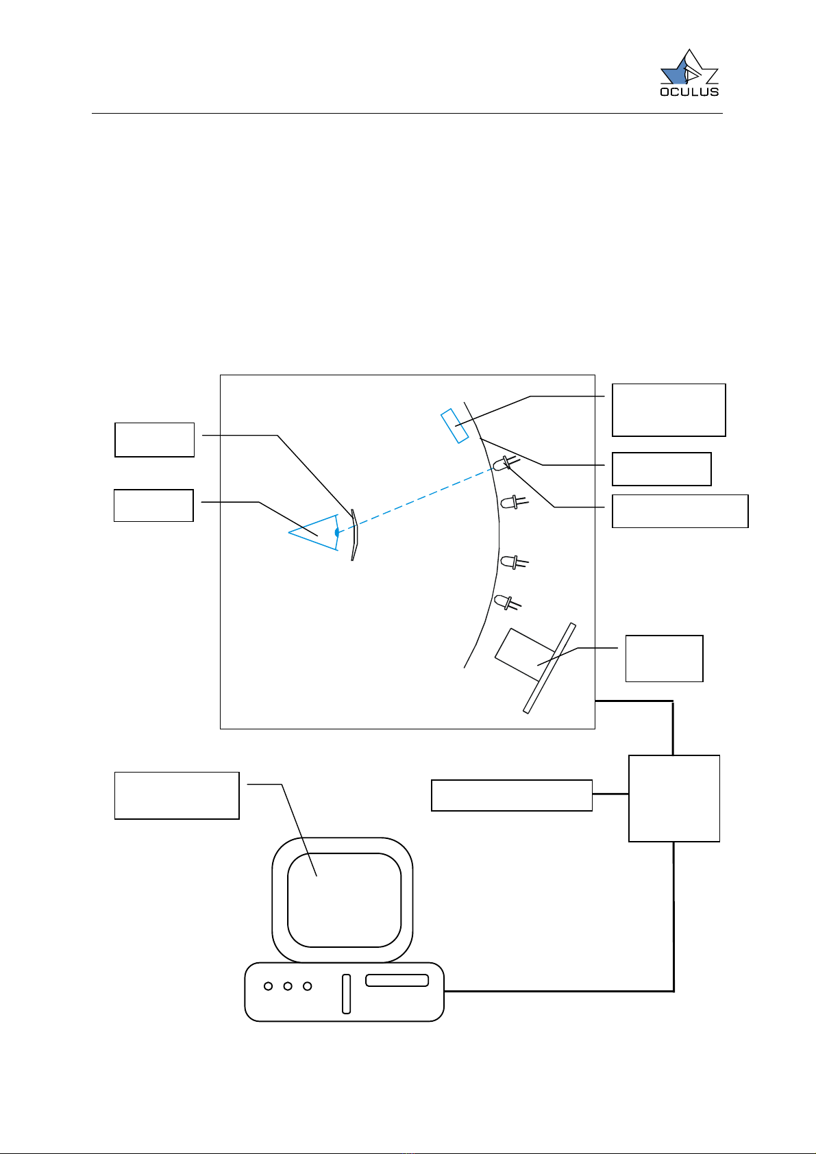
5 The basic operation principal of the system .................................................................. 5
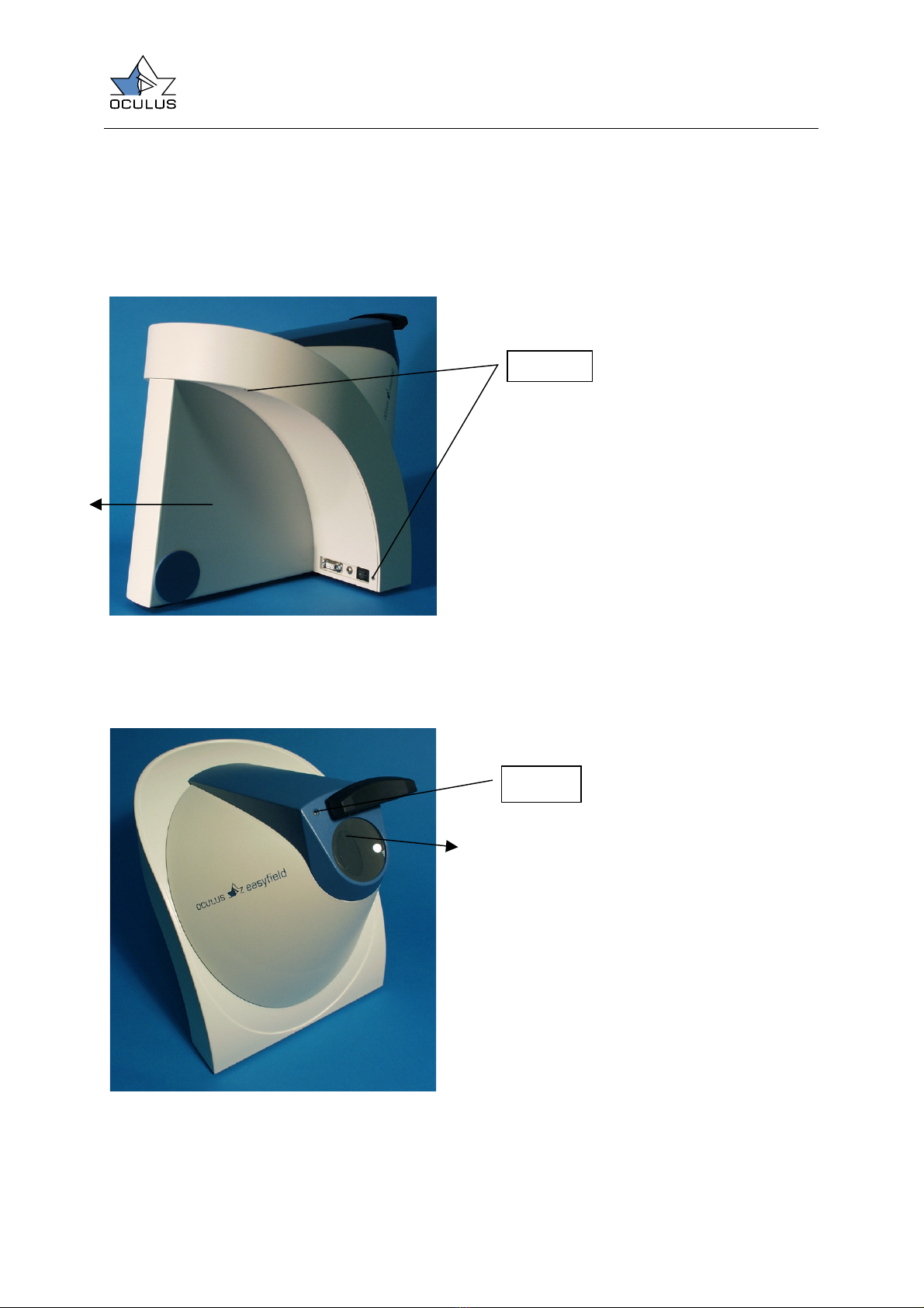
6 Easyfield.................................................................................................................. 6
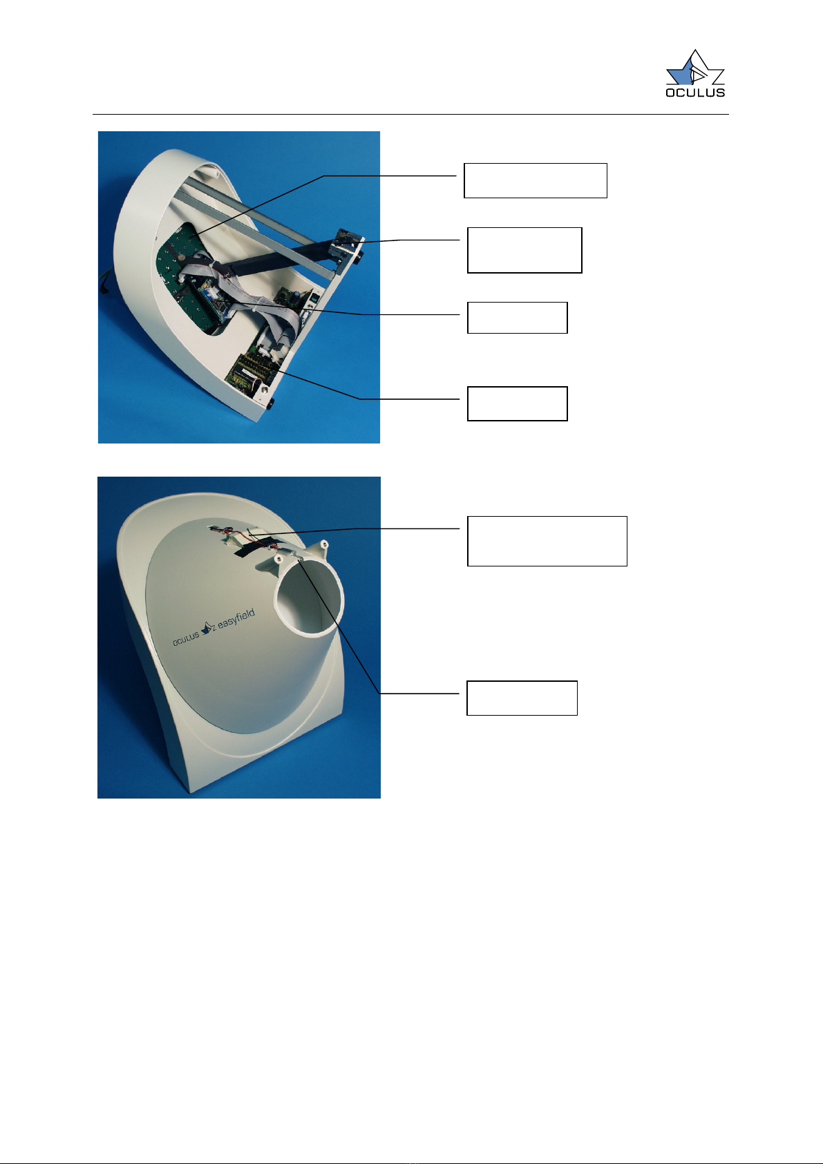
6.1 Opening the housing ........................................................................................... 6
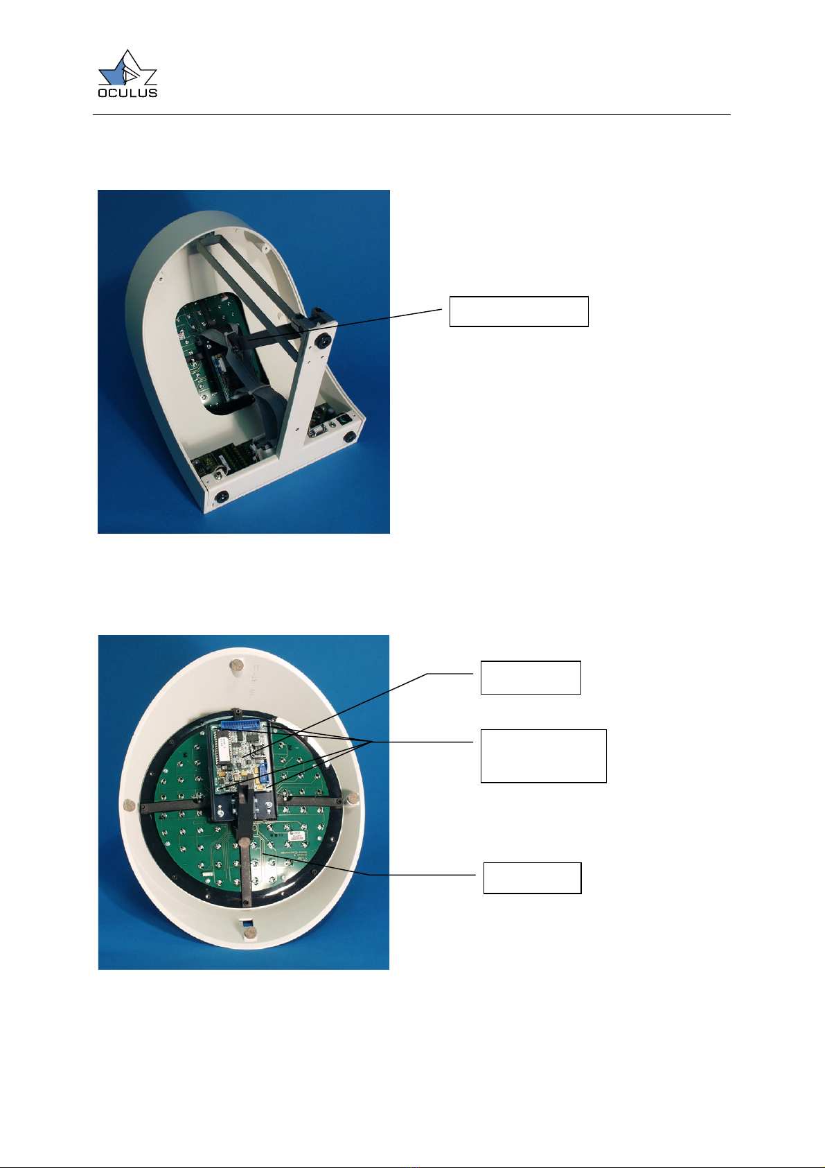
6.2 Remove the cupola ............................................................................................. 8
6.2.1 Set up the CCD image ...................................................................................... 9
6.2.2 Dismounting the CCD board ............................................................................ 10
6.2.3 Board description ........................................................................................... 11
6.2.4 EF01 board ................................................................................................... 11
6.2.5 CCD board.................................................................................................... 12
6.2.6 LED board..................................................................................................... 13
6.3 Power supply ................................................................................................... 14
6.4 Hand held unit.................................................................................................. 14
6.4.1 Opening the housing ...................................................................................... 14
6.4.2 Control board ................................................................................................ 15
7 Troubleshooting...................................................................................................... 16
8 Appendix............................................................................................................... 17
8.1 List of parts ..................................................................................................... 17

page 3
Service manual Easyfield
1Safety Precautions
The OCULUS Easyfield is a sensitive
measuring instrument. Repairs must be done
by authorized persons and with original parts
from OCULUS only.
•Read the Users Manual first. The user
must be trained before starting the
system.
•The user must be educated in using
medical devices.
•The system shall be installed at a safe
place where it is be protected from direct
sunshine, flammables and high humidity.
•Protect the unit also from dust, extreme
temperatures, and water.
•The unit must be used with the proper
electrical voltage and frequency only.
•Do not use other cables for connecting
the device.
•Users are not allowed to open the system
and to make any changes.
•When the system does not operate
normally, users are requested to inform
the manufacturer or the distributor.
2Component description
Figure 1
Figure 2
Head rest
PC: serial port
RS232
Power switch
Plug for power
su
pp
l
y
Response button

Service manual Easyfield
page 4
3System requirement
3.1 PC
The device EASYFIELD is controlled by a
standard PC or with the handheld unit. If
controlled by a PC (or Laptop) it must have
the following requirements:
•PC 486DX4 min. 100 MHz
•RAM 16 Mbytes
•Harddisk min. 1.7 Gbyte
•Windows NT/2000/XP, Windows
95/98/ME
•VGA 640*480 Pixel with min. 256
Colors
3.2 Mains power
The power supply needs AC Voltage 100-
240 Volt ~, 50Hz - 60Hz, 0,75A – 0,35A.
Output: +12V =, 2,75A.
4System setup
4.1 PC connection
The Easyfield works with a standard RS232
serial interface with 115200Baud.
4.2 Wiring
Caution: Do not connect or disconnect any
cable while the PC or the Easyfield is
switched on!
If the Easyfield should work with the PC
connect the unit with the PC by using a
9 pin (one to one) extention cable (D plugs).
Connect the Easyfield unit with the power
supply.

page 5
Service manual Easyfield
5The basic operation principal of the system
•A LED-bar (3) illuminates the cupola (4)
indirectly.
•A testpoint (5) is presented to the
surface of the cupola by switching on a
testpoint-LED.
•The patient’s eye (1) sees a virtual
image of the cupola through the lens (2)
•The CCD-Camera (6) observe the eye of
the patient while the examination is
running.
•Using the response button (8) the
patient signals seeing or not seeing the
testpoint.
•Data is compressed by a Microcontroller
(7) and is transferred to the PC or to the
hand held unit (9).
•The PC or the hand held unit evaluates
all data and shows a colored map of the
viewfield.
1 (Eye)
2 (Lens)
3 (Background
illumination)
4 (Cupola)
6 (CCD
Camera)
5 (Testpoint LED)
7 (Micro-
controller)
8 (Response button)
9 (PC or
Hand held unit)

Service manual Easyfield
page 6
6Easyfield
6.1 Opening the housing
Before opening the perimeter disconnect all
plugs it is connected to.
Figure 3
Unscrew the four screw at the back of the
unit and remove the back part of the
housing by pulling it in the direction as
marked on the picture.
Figure 4
Dismount the lens holding part of the
housing by moving the forehead rest and
remove the two screws under it. Remove
the housing by pulling it in the direction as
marked on the picture.
Screws
Screws

page 7
Service manual Easyfield
Figure 5
Figure 6
LED-board
CCD-board
EF01 board
Cupola
moving axis
Infrared diode
LED row for back-
ground illumination

Service manual Easyfield
page 8
6.2 Remove the cupola
Figure 7
Unplug the flat ribbon cables from the EF01
board to the testpoint board and cut the
cable ties.
Figure 8
Two Allen screws
CCD board
LED board
Screws holding
the CCD board

page 9
Service manual Easyfield
6.2.1 Set up the CCD image
The CCD camera has been set up by
OCULUS for best picture. If the unit has to
be dismount for repairing it is possible that
the picture gets blur or disoriented after
mounting it together. You have to set up the
CCD manually. Mount the device completely
but the back of the holding and connect it to
the hand held unit or the PC until you have a
picture on the CCD. Be sure to connect both
cables to the CCD board! – Connecting one
cable only will destroy the board. The
pictures position can be changed by
unlocking the screws 1 (cf. Figure 9) and
moving the CCD board (The CCD board in
this figure has been removed from the unit
for better sight). The sharpness can be
adjusted by unlocking screws 2 (both sides)
and moving the board towards (or
backwards) the cupola.
Figure 9
CCD board mounted on cross holder
Screws 1 for
CCD position
Screws 2 for
CCD sharpness

Service manual Easyfield
page 10
6.2.2 Dismounting the CCD board
Remove the screws described in Figure 8
and pick up the CCD board from its holder.
Figure 10 (Front side)
Figure 11 (Back side)
Figure 12 (Back side without CCD chip)
If the camera picture looks like a chessboard
or has got vertical or horizontal stripes the
CCD board may have a malfunction. If the
Camera picture is black only the CCD chip
can be defect. In case of the CCD chip has
to be replaced be sure to put it the correct
direction inside the base (cf. Figure 12).
Pin 1

page 11
Service manual Easyfield
6.2.3 Board description
6.2.4 EF01 board
The internal functions of the measuring
device are controlled by a PIC
Microcontroller. It controls perimetric
measurement, data transmission and
measuring procedure. Because of the
individual brightness of the testpoint LEDs
on the LED board (cf. 6.2.6, page 13) the
unit has to be calibrated. The calibration
values are stored on the EF01 boards
Eeprom.
Caution: If the EF01 board has to be
replaced it is not enough to change the
eeprom to get the correct calibration data.
The device has to be completely
recalibrated.
Figure 13
To LED board
right connector
To LED board
left connector
To CCD board
To CCD board
Eeprom
containing the
calibration data

Service manual Easyfield
page 12
6.2.5 CCD board
This board has a single CCD chip which
produces a picture of the patient’s eye. This
½ inch CCD (Sony ICX039BLA) uses a
resolution of 582x752 Pixel The board is
directly connected with the EF01 board.
To EF01
board
To EF01
board

page 13
Service manual Easyfield
6.2.6 LED board
This board contains all the testpoint LEDs
and fixation marks which are projected
inside the cupola. This board is connected
directly to the EF01 board which controls
the testpoints. Also this board has got a
connector for the background illumination
and the infrared LED which illuminates the
patients eye.
Figure 14
To EF01 board
upper connector
To EF01 board
bottom connector

Service manual Easyfield
page 14
6.3 Power supply
The power supply type SW172 needs 100-
240V with 50-60Hz input. The output
voltage is +12V, 2,75A.
6.4 Hand held unit
6.4.1 Opening the housing
To open the housing just remove the printers
cover by pulling it in the direction described
on Figure 15. Unscrew the four screws on
the bottom of the unit and remove the plate.
Figure 15
Figure 16
LC Display
Printer
Control buttons
Control knob
Printer
Serial plug
to Easyfield

page 15
Service manual Easyfield
Figure 17
6.4.2 Control board
The control board as it named controls the
perimeter completely. It contains the whole
examination program and has got space for
40000 examinations.
Control board
Control button board
Control
knob
RS232
Connector
Buttons
near LCD
Software Up-
date Jumper
To printer
Button,
Right
Button, Left
To inverter
To LCD

Service manual Easyfield
page 16
7Troubleshooting
Malfunction Possible cause Remedy
CCD picture looks like a
chessboard or has got vertical
or horizontal stripes
CCD board is defect The CCD board has to be
exchanged (cf. 6.2.2, page 10)
CCD picture is dark Brightness is not set up
correctly
Set up the CCD brightness
(cf. Users manual)
Infrared LED for illumination of
patient’s eye is defect
Replace the infrared LED
(cf. Figure 6)
CCD chip is defect Replace the CCD Chip
(cf. 6.2.2, page 10)
Testpoint LED does not
illuminate
LED is defect LED has to be replaced.
Caution! The LED has to be
recalibrated!
CCD picture is blur CCD board is not set up
correctly
Install the CCD board
(cf. 6.2.1, page 9).
CCD picture is disoriented CCD board is not set up
correctly
Install the CCD board
(cf. 6.2.1, page 9).
One of the hand held units
control buttons does not work
The button is defect Replace this button by a new
one (cf. Figure 17, page 15)

page 17
Service manual Easyfield
8Appendix
8.1 List of parts
piece construction no. Name material
1 56930-03-000 Easyfield
1 56930-03-001 Basis
1 56930-03-003 Lever AlMg3
1 56930-03-005 Axis Nirosta
1 56930-03-009 Cross carrier
1 56930-03-010 Interface holder St37K
1 56930-03-011 Brace St37K
1 56930-03-012 Flat support Zinkcor
1 56930-03-013 Reflector PS + 0.1% yellow
1 56930-03-014 Cross carrier raw
1 56930-03-015 Bearing holder St37K
1 56930-03-016 Bearing holder, raw St37K
1 56930-03-017 EF01
1 56930-03-018 Background-board
1 56930-03-019 LED-board
1 56930-03-020 Cable for response button
1 56930-03-021 COM-Cable
2 56930-03-022 Flat ribbon cable 14-pol.
1 56930-03-023 Background-cable
1 56930-03-024 12V-Cable
2 56930-03-025 Felt t3 d12 0.28g/ccm
1 56930-03-026 Camera holder AlMg3
2 56930-03-027 Camera angle AlMg3
1 56930-03-030 Funnel, complete
1 56930-03-031 Additional Facing, complete
1 56930-03-032 Housing back, complete
1 56930-03-033 Basis, complete
1 56930-03-034 Basic unit, complete
1 56930-03-036 IR LED
1 56930-03-037 fix-o-moll
4 56930-03-038 Felt t4 d12 0.36g/ccm Le basic white
12 05170390 LED white, 2.8cd, 20°, d=3 WU-7-730SWC
1 05310110 CCD-Chip ICX039BLA-6
1 56900-11-002 CCD-Camera board
1 56950-13-007 Flat ribbon cable 10-pol.
1 56900-10-004 Flat ribbon cable 26-pol.
1 56950-01-026 Meniscus lens +3dpt BK7
4 05320030 Spacer d3.5,D7,h3 NYL
2 56950-01-042 Clamp 10 Hostaform C9021
2 56950-01-043 Clamp 26 Hostaform C9021
3 05222100 Cable clamp
1 05270220 Flat ferrite EFC-40MN-2
1 04049206 Cylinder bolt 2m6x6 Nirosta
3 05330295 Pedestal
2 05350150 Latch
2 05320285 Spacer

Service manual Easyfield
page 18
4 05400050 Cup spring 10x5.2x0.5x0.75 SN2000
2 04020775 Hexagonal nut M4 DIN934 zinc-coated
4 04030030 Washer A3.2 DIN125
2 04030070 Washer A4.3 DIN125 zinc-coated
1 04030105 Washer 6.3x10x0.8
2 04060160 Locking pin 4x18 DIN1481
4 04119150 Counter-sunk screw M3x8 DIN965 Nirosta
2 04119150 Counter-sunk screw M3x8 DIN965 Nirosta
4 04190230 Cylinder head screw M2x8 DIN84
4 04210002 Allen M3x6 with integrated washer DIN912 zinc-coated
3 04210002 Allen M3x6 with integrated washer DIN912 zinc-coated
2 04210002 Allen M3x6 with integrated washer DIN912 zinc-coated
4 04210002 Allen M3x6 with integrated washer DIN912 zinc-coated
4 04210006 Allen screw M3x16 DIN912
4 04210011 Allen screw M3x8 DIN912
2 04210035 Allen screw M4x12 DIN912
2 04210065 Allen screw M4x20 DIN912
2 04219408 Allen screw M4x8 DIN912 Nirosta
3 04219408 Allen screw M4x8 DIN912 Nirosta
2 04240310 Tapping screw B2.2x6.5 DIN7981 Ni-coated
2 04210050 Allen screw M4x16 DIN912
2 04210035 Allen screw M4x12 DIN912 zinc-coated
Table of contents
Other OCULUS Medical Equipment manuals

OCULUS
OCULUS Corvis ST User manual

OCULUS
OCULUS Easygraph 70620 User manual

OCULUS
OCULUS Pentacam User manual

OCULUS
OCULUS Myopia Master Advanced User manual

OCULUS
OCULUS GramaDerm User manual

OCULUS
OCULUS BIOM ready User manual

OCULUS
OCULUS Pentacam AXL User manual

OCULUS
OCULUS UB 4 User manual

OCULUS
OCULUS ImageCam 3 User manual

OCULUS
OCULUS Myopia Master Basic User manual