2
Operating Instructions and Parts Manual 24495
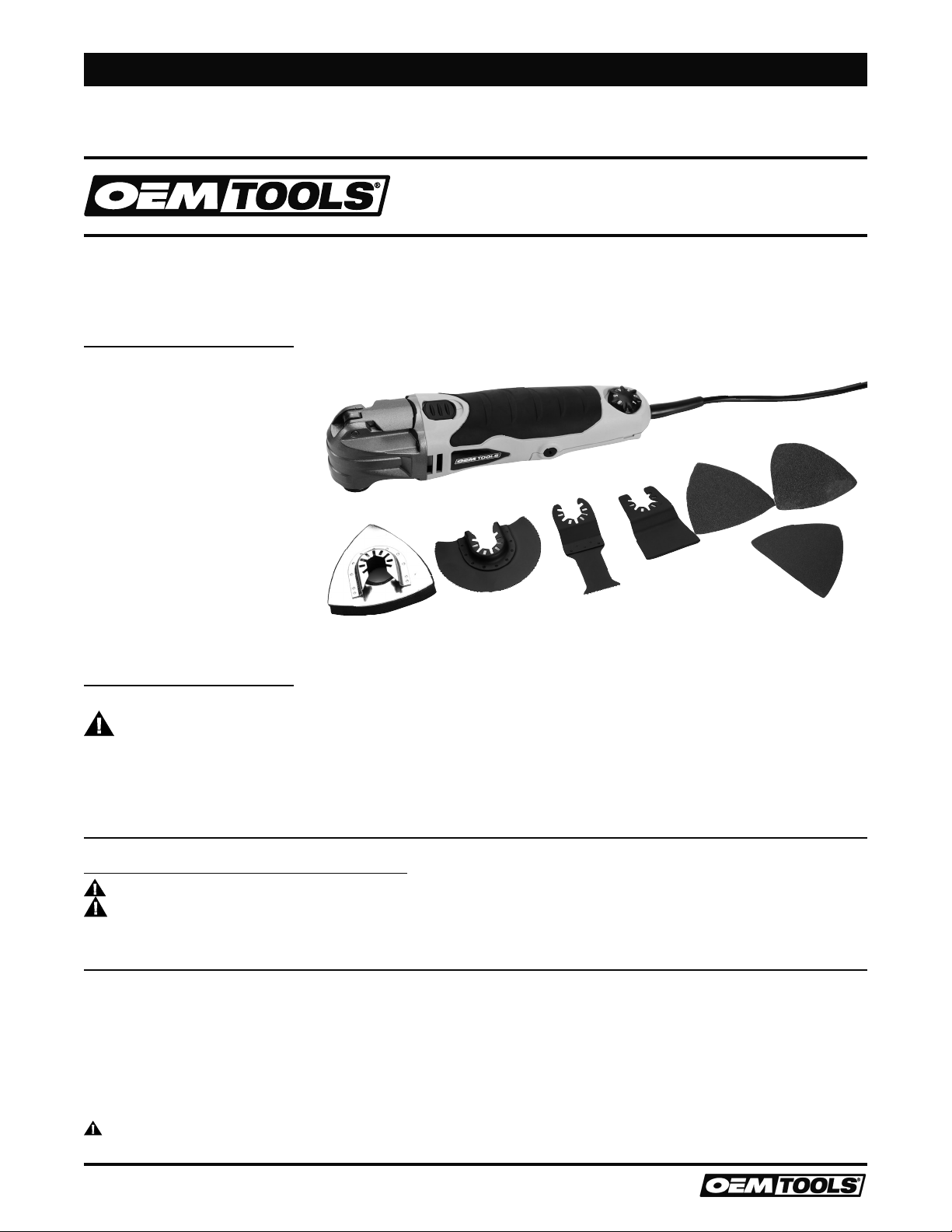
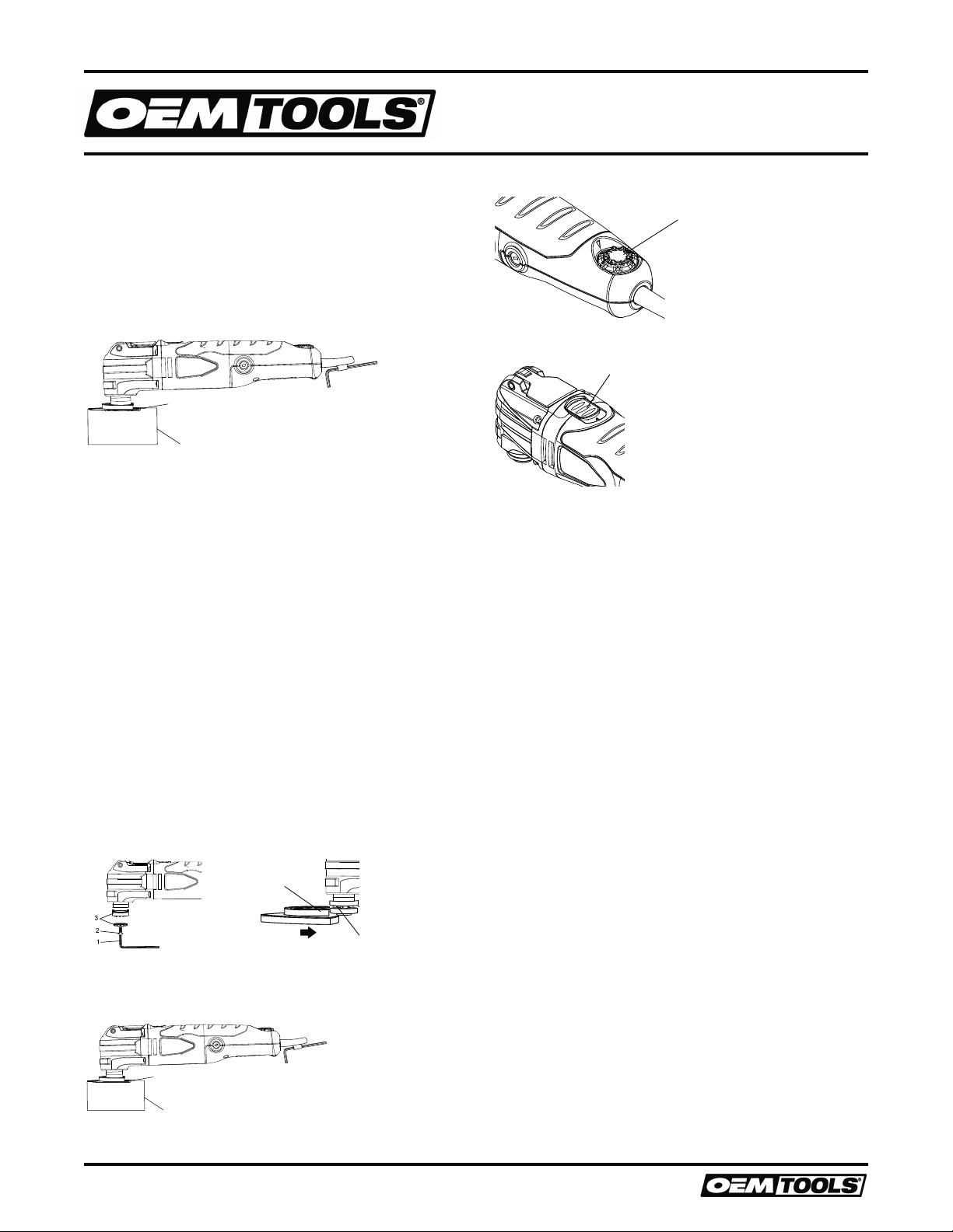
OSCILLATING TOOL
1/17
2017 OEMTOOLS®
POWER TOOL SAFETY
Read and understand all safety warnings and instructions. Failure to
follow the warnings and instructions may result in electric shock, fire and/
or serious injury. Save all warnings and instructions for future reference.
WARNING
WORK AREA SAFETY
1. Keep work area clean and well lit. Cluttered or dark areas invite
accidents.
2. Do not operate power tools in explosive atmospheres, such as in the
presence of flammable liquids, gases or dust. Power tools create sparks
which may ignite the dust or fumes.
3. Keep children and bystanders away while operating a power tool.
Distractions can cause you to lose control.
ELECTRICAL SAFETY
1. Power tool plugs must match the outlet. Never modify the plug in any
way. Do not use any adapter plugs with earthed (grounded) power tools.
Unmodified plugs and matching outlets will reduce risk of electric shock.
2. Avoid body contact with earthed or grounded surfaces such as pipes,
radiators, ranges and refrigerators. There is an increased risk of electric
shock if your body is earthed or grounded.
3. Do not expose power tools to rain or wet conditions. Water entering a
power tool will increase the risk of electric shock.
4. Do not abuse the cord. Never use the cord for carrying, pulling or
unplugging the power tool. Keep cord away from heat, oil, sharp edges
or moving parts. Damaged or entangled cords increase the risk of
electric shock.
5. When operating a power tool outdoors, use an extension cord suitable
for outdoor use. Use of a cord suitable for outdoor use reduces the risk
of electric shock.
6. If operating a power tool in a damp location is unavoidable, use a
residual current device (RCD) protected supply. Use of a ground fault
circuit interrupter (GFCI) reduces the risk of electric shock.
PERSONAL SAFETY
1. Stay alert, watch what you are doing and use common sense when
operating a power tool. Do not use a power tool while you are tired
or under the influence of drugs, alcohol or medication. A moment of
inattention while operating power tools may result in serious personal
injury.
2. Use personal protective equipment. Always wear eye protection. Protective
equipment such as dust mask, non-skid safety shoes, hard hat, or hearing
protection used for appropriate conditions will reduce personal injuries.
3. Prevent unintentional starting. Ensure the switch is in the off-position
before connecting to power source and/or battery pack, picking up or
carrying the tool. Carrying power tools with your finger on the switch or
energizing power tools that have the switch on invites accidents.
4. Remove any adjusting key or wrench before turning the power tool on.
A wrench or a key left attached to a rotating part of the power tool may
result in personal injury.
5. Do not overreach. Keep proper footing and balance at all times. This
enables better control of the power tool in unexpected situations.
6. Dress properly. Do not wear loose clothing or jewelry. Keep your hair,
clothing and gloves away from moving parts. Loose clothes, jewelry or
long hair can be caught in moving parts.
7. If devices are provided for the connection of dust extraction and
collection facilities, ensure these are connected and properly used. Use
of dust collection can reduce dust-related hazards.
POWER TOOL USE AND CARE
1. Do not force the power tool. Use the correct power tool for your
application. The correct power tool will do the job better and safer at the
rate for which it was designed.
2. Do not use the power tool if the switch does not turn it on and off. Any
power tool that cannot be controlled with the switch is dangerous and
must be repaired.
3. Disconnect the plug from the power source and/or the battery pack from
the power tool before making any adjustments, changing accessories,
or storing power tools. Such preventive safety measures reduce the risk
of starting the power tool accidentally.
4. Store idle power tools out of the reach of children and do not allow
persons unfamiliar with the power tool or these instructions to operate
the power tool. Power tools are dangerous in the hands of untrained
users.
5. Maintain power tools. Check for misalignment or binding of moving
parts, breakage of parts and any other condition that may affect the
power tool’s operation. If damaged, have the power tool repaired before
use. Many accidents are caused by poorly maintained power tools.
6. Keep cutting tools sharp and clean. Properly maintained cutting tools
with sharp cutting edges are less likely to bind and are easier to control.
7. Use the power tool, accessories and tool bits etc. in accordance with
these instructions, taking into account the working conditions and the
work to be performed. Use of the power tool for operations different
from those intended could result in a hazardous situation.
8. Hold power tool by insulated gripping surfaces, because the blade may
contact its own cord. Cutting a “live” wire may make exposed metal
parts of the tool “live” shock the operator.
9. Use clamps or another practical way to secure and support the
workpiece to a stable platform. Holding the work by hand or against
your body leaves it unstable and may lead to loss of control.
SERVICE
Have your power tool serviced by a qualified repair person using only
identical replacement parts. This will ensure that the safety of the power
tool is maintained.
SPECIFIC SAFETY RULES
WARNING
1. Know your oscillating tool. Do not plug the tool into the power source
until you have read and understand this Instruction Manual. Learn the
tool’s applications and limitations, as well as the specific potential
hazards related to this tool. Following this rule will reduce the risk of
electric shock, fire, or serious injury.
2. ALWAYS wear eye protection. Any power tool can throw foreign
objects into your eyes and cause permanent damage. ALWAYS wear
safety goggles (not glasses) that comply with ANSI safety standard
Z87.1. Everyday glasses have only impact resistant lenses. They ARE
NOT safety glasses.
3. Glasses or goggles not in compliance with ANSI Z87.1 could cause
serious injury when they break.
4. Always keep hands out of the path of the saw blade. Avoid awkward
hand positions where a sudden slip could cause your hand to move into
the path of the saw blade.
5. Secure workpiece. Use clamps or a vice to hold the workpiece. It is safer
than using your hand and it frees both hands to operate the tool.
6. Make sure there are no nails or foreign objects in the part of the
workpiece to be cut or sanded.
7. To avoid injury from accidental starting, always remove the plug from
the power source before installing or removing an accessory.
8. Never use dull blades in the tool. They will cut slower, leave rough cuts
and break easily due to added pressure and excessive heat. They will
also overload the motor and cause premature failure of the tool.
9. Never use damaged or bent blades. They will be brittle and break easily
possibly causing injury to the operator.
10.Never touch a saw blade immediately after using the tool. The blade will
be extremely hot and will burn your hand.
11.Only use accessories designed for use with this tool.