ENGLISH
CHAPTER................................................. 1
Chapter for the technician and operator
1.1 GENERAL WARNINGS ..................................... Page GB-3
1.2 REFERENCE NORMATIVE...............................Page GB-4
1.3 DESCRIPTION OF THE SYMBOLS .................. Page GB-4
1.4 OVEN COMPOSITION ...................................... Page GB-4
1.5 PREARRANGEMENTS AT PURCHASER’S
CHARGE............................................................Page GB-5
1.6 EMERGENCY OPERATIONS IN CASE
OF FIRE.............................................................Page GB-5
1.7 EXPLOSION RISK.............................................Page GB-5
1.8 ACOUSTIC PRESSURE LEVEL ....................... Page GB-5
CHAPTER................................................. 2
Chapter for the technician
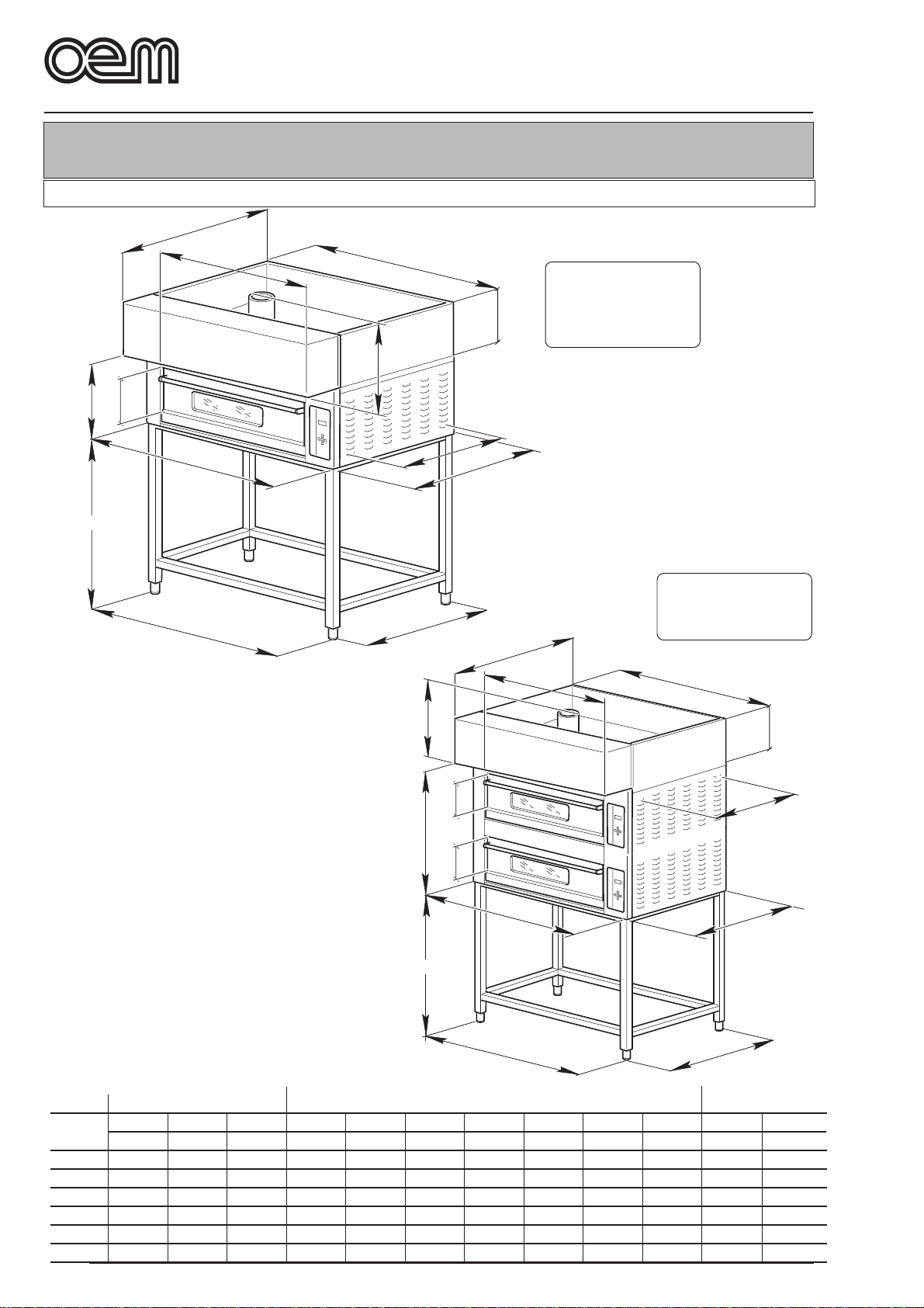
-OVERALL DIMENSIONS........................................ Page GB-6
2.1
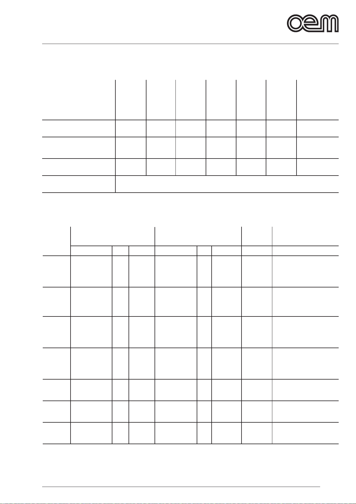
TECHNICAL FEATURES
................................. Page GB-7
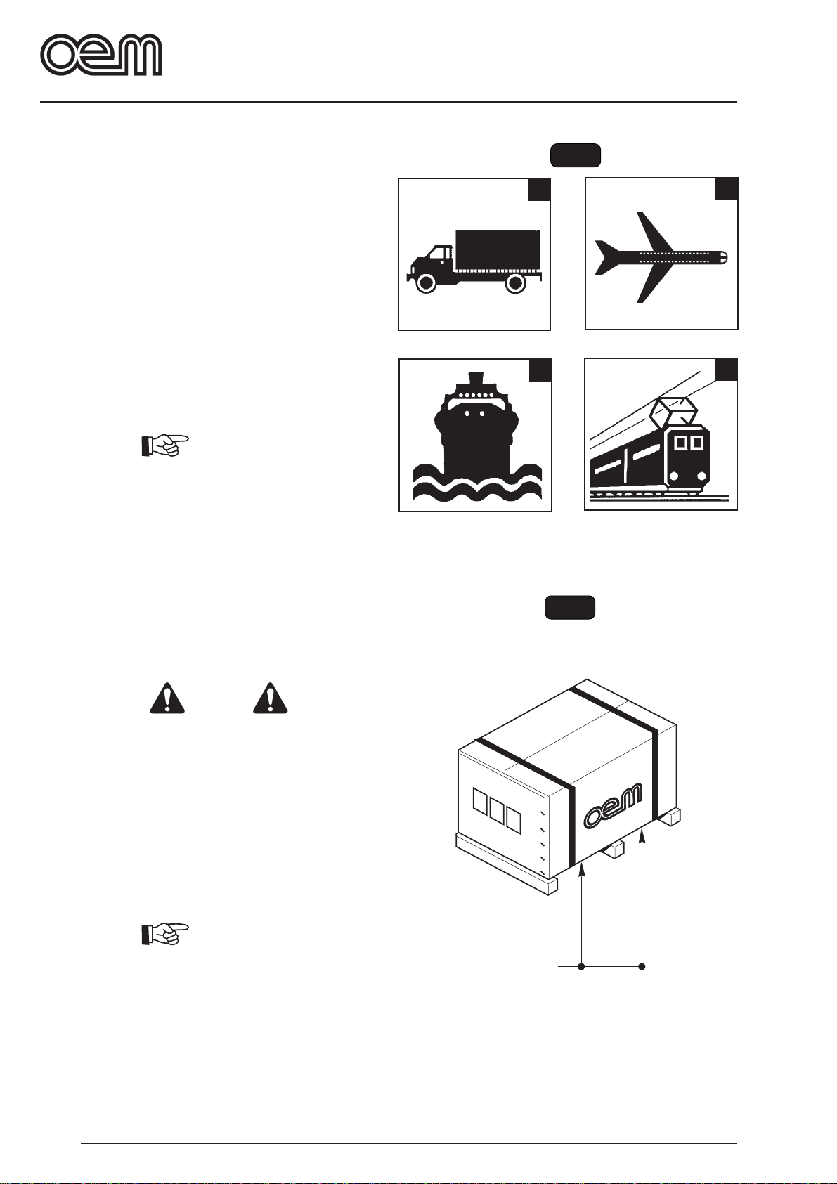
2.2 TRANSPORT..................................................... Page GB-8
2.2.a Shipment...................................................Page GB-8
2.2.b Lifting of the packing................................. Page GB-8
2.2.c Storage ..................................................... Page GB-8
2.3 RECEPTION OF THE MACHINE ...................... Page GB-9
2.4 UNPACKING ......................................................Page GB-9
2.5 IDENTIFICATION OF THE COMPONENTS ....Page GB-10
2.6 OVEN IDENTIFICATION................................. Page GB-10
CHAPTER................................................. 3
Chapter for the technician
3.1 OVEN LIFTING ................................................ Page GB-11
3.2 ASSEMBLING OF THE COMPONENTS.........Page GB-11
3.3 ELECTRICAL CONNECTION..........................Page GB-13
3.3.a Electric oven connection ......................... Page GB-13
3.3.b Electric hood connection ........................ Page GB-14
3.3.c Unipotential connection...........................Page GB-14
3.4 OVEN POSITIONING ......................................Page GB-14
3.4.a Chimney connection ............................... Page GB-14
3.5 FIRST STARTING ............................................Page GB-14
CHAPTER................................................. 4
Chapter for the technician and operator
4.1 TYPE OF USE AND CONTRAINDICATIONS.. Page GB-15
4.2 SAFETY PLATES.............................................Page GB-15
4.3 SAFETY DEVICES .......................................... Page GB-16
4.4 USER’S AREAS...............................................Page GB-16
4.5 RESIDUAL DANGER AREAS.......................... Page GB-16
CHAPTER................................................. 5
Chapter for the technician and operator
5.1 CONTROL BOARD AND PILOT LIGHTS ON
DIGITALLY CONTROLLED OVENS................. Page GB-17
5.2 MANUAL OVEN CONTROL BOARD...............Page GB-18
5.3 OVEN PREPARATION ..................................... Page GB-19
5.3.a General rules to bake on refractory
surfaces ..................................................Page GB-19
5.3.b General rules to bake in baking-tin ......... Page GB-19
5.3.c Oven starting .......................................... Page GB-20
5.4 PIZZA BAKING ................................................ Page GB-21
5.5 ALARM CONDITIONS DURING OVEN
FUNCTIONING ................................................Page GB-21
5.5.a ATemperature feeler alarm is damaged or
disconnected ................................................... Page GB-21
5.6 SELF-CLEANING CYCLE ............................... Page GB-22
5.7 CUTTING OFF.................................................Page GB-22
5.8 MALFUCTIONING,CAUSE AND CURE ..........Page GB-23
5.9 SAFETY THERMOSTAT RECHARGE............. Page GB-23
CHAPTER................................................. 6
Chapter for the technician and operator
6.1 ROUTINE AND PLANNED MAINTENANCE ...Page GB-24
6.1.a In general ...............................................Page GB-24
6.1.b Ordinary maintenance ........................... Page GB-24
6.1.b - a Outer cleaning
(to be carried out every day) ........................... Page GB-24
6.1.b - b Fireproof surface cleaning (to be
carried out every day) ..................................... Page GB-24
6.1.c Planned maintenance ............................Page GB-25
6.1.c - a Every 600 hours a careful
chamber cleaning .............................Page GB-25
6.1.c - b Every 2 years.................................... Page GB-25
6.1.d Maintenance in case of need.................Page GB-25
6.1.d - a Lamp holder replacement.................Page GB-25
6.1.d - b Lamp replacement............................Page GB-26
6.1.d - c Ceiling or bedplate resistance
replacement...................................... Page GB-26
6.1.d - d Door spring replacement .................. Page GB-27
6.1.d - e Door pane replacement .................... Page GB-28
CHAPTER................................................. 7
Chapter for the technician
7.1 OVEN DISASSEMBLY .................................... Page GB-29
7.2 OVEN SCRAPPING ........................................ Page GB-29
7.3 DISPOSING OF HARMFUL SUBSTANCES.... Page GB-29
WIRING DIAGRAM MM/D-E 435 - V400-230
Three-phase/V230 Single-phase ................... Page. GB-30
WIRING DIAGRAM MB/D-E 835 - V400 ............... Page. GB-31
WIRING DIAGRAM MB/D-E 835 - 230V
Three-phase ................................................... Page. GB-32
WIRING DIAGRAM MM/MB/E-D - 635S/L - 935 -
1235S/L - 230V Three-phase ......................... Page. GB-33
SCHEMA WIRING DIAGRAM MM/MB/E-D - 635S/L - 935 -
1235S/L - 400V .............................................. Page. GB-34
OVEN CAPTION MM435 E/D .............................. Page. GB-35
OVEN CAPTION MB 835 E/D ............................... Page. GB-35
OVEN CAPTION MM.E.D.-635S-635L-935 +
MB.E.D.-1235S-1235L ................................... Page. GB-35