Oki C9300 Series User manual


i
Contents
Introduction. . . . . . . . . . . . . . . . . . . . . . . . . . . . . . . . . . . . . . 1
Section 1
Finisher Installation . . . . . . . . . . . . . . . . . . . . . . . . . . . . . . 3
Primary Procedures . . . . . . . . . . . . . . . . . . . . . . . . . . . . . . . 3
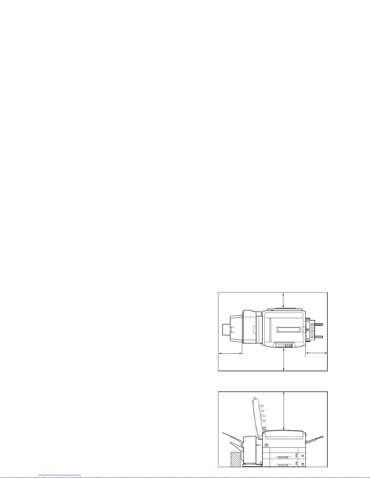
Checking installation space . . . . . . . . . . . . . . . . . . . . . . . . . 4
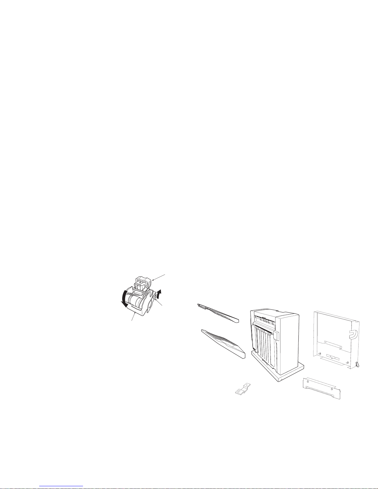
Unpacking the Finisher . . . . . . . . . . . . . . . . . . . . . . . . . . . . 5
Activating the Stapler .......................................................5
Identifying component items (Finisher) . . . . . . . . . . . . . . . 6
Finisher Height Requirements .......................................... 7
Supply List........................................................................ 7
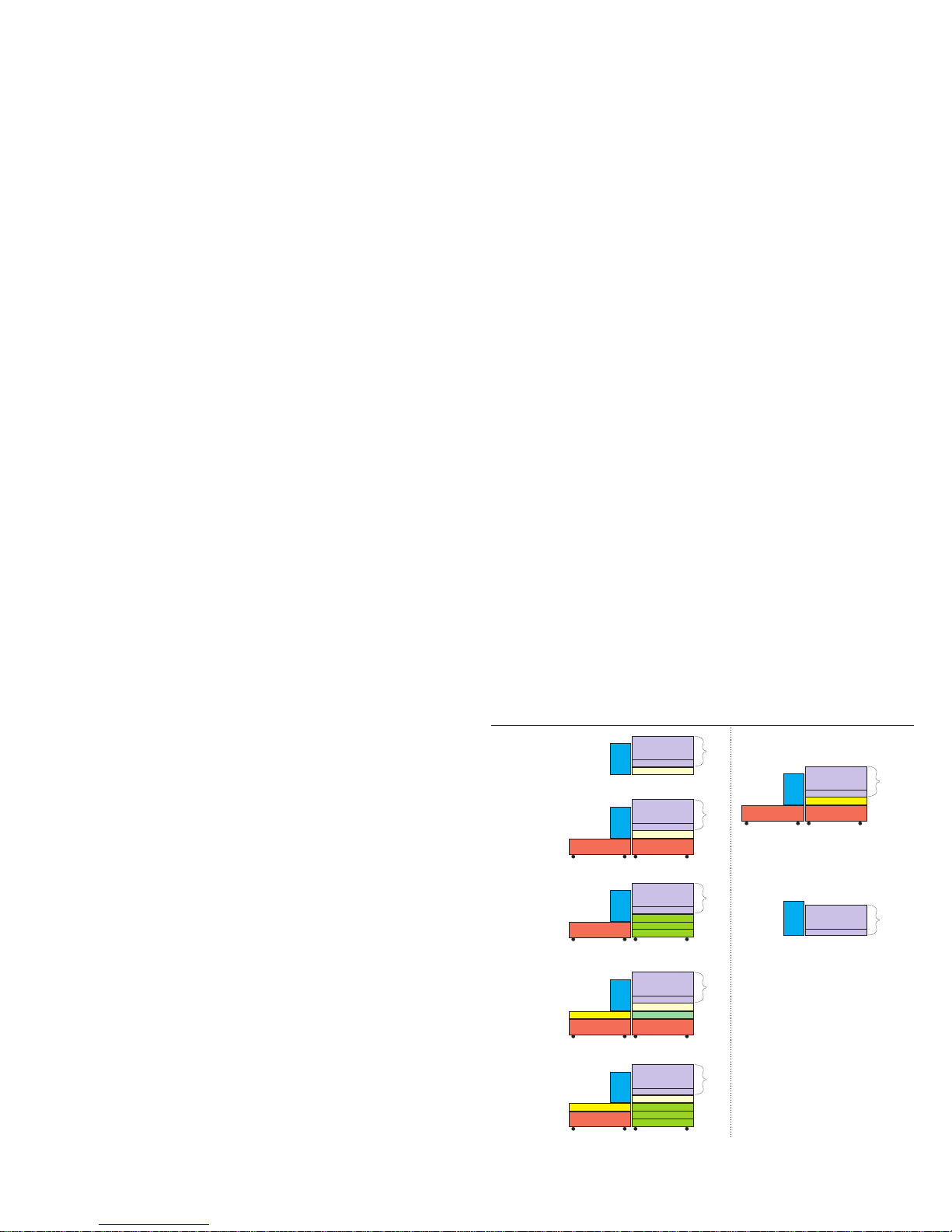
Configuration Options ............................................................. 7
Installing the Finisher . . . . . . . . . . . . . . . . . . . . . . . . . . . . . 8
Checking the Finisher. . . . . . . . . . . . . . . . . . . . . . . . . . . . . . 12
Checking the Finisher Settings. . . . . . . . . . . . . . . . . . . . . . . 12
Printing a Menu Map . . . . . . . . . . . . . . . . . . . . . . . . . . . . . . 13
Printing a Demo Page. . . . . . . . . . . . . . . . . . . . . . . . . . . . . . 13
Checking the Finisher Operation . . . . . . . . . . . . . . . . . . . . . 13
Section 2
Identifying component items . . . . . . . . . . . . . . . . . . . . . . . 14
Finisher . . . . . . . . . . . . . . . . . . . . . . . . . . . . . . . . . . . . . . . . . 14
Overall configuration . . . . . . . . . . . . . . . . . . . . . . . . . . . . . . 15
Finisher Usage . . . . . . . . . . . . . . . . . . . . . . . . . . . . . . . . . . . . 16
Before you begin . . . . . . . . . . . . . . . . . . . . . . . . . . . . . . . . . 16
General . . . . . . . . . . . . . . . . . . . . . . . . . . . . . . . . . . . . . . . . . 16
Stacker summary information........................................... 16
Punching information . . . . . . . . . . . . . . . . . . . . . . . . . . . . . 17
Allowable paper sizes....................................................... 17
Allowable paper weight ................................................... 17
Hole positions................................................................... 17
Punching procedure.......................................................... 17
Stapling information . . . . . . . . . . . . . . . . . . . . . . . . . . . . . . 17
Allowable paper sizes....................................................... 17
Allowable paper weight ................................................... 17
Staple position .................................................................. 18
Stapling procedure ........................................................... 18
Job offset information . . . . . . . . . . . . . . . . . . . . . . . . . . . . . 18
Allowable paper sizes....................................................... 18
Job offset position ............................................................ 18
Job offset procedure ......................................................... 18
Printer Control Panel Settings . . . . . . . . . . . . . . . . . . . . . . 19
PRINT MENU options..................................................... 19
USAGE MENU options................................................... 20
Print Driver Setting . . . . . . . . . . . . . . . . . . . . . . . . . . . . . . . 20
Finisher-related settings . . . . . . . . . . . . . . . . . . . . . . . . . . . . 20
Windows 95/98/Me .......................................................... 21
PostScript printer driver 21
PCL Printer Driver 22
Windows 2000/XP ........................................................... 23
PostScript printer driver 23
PCL Printer Driver 24
Windows NT .................................................................... 25
PostScript printer driver 26
PCL Printer Driver 27
Macintosh OS X ............................................................... 28
Macintosh OS Classic (OS 8.6-9.2.2) .............................. 28

ii
Troubleshooting . . . . . . . . . . . . . . . . . . . . . . . . . . . . . . . . . . 30
Counteracting paper curl . . . . . . . . . . . . . . . . . . . . . . . . . . . 30
Setting the Decurler Lever................................................ 31
Clearing a paper jam. . . . . . . . . . . . . . . . . . . . . . . . . . . . . . . 31
Locations 361 and 362 32
Locations 363 and 364 33
Locations 365 and 367 34
Location 366 34
Removing jammed staples . . . . . . . . . . . . . . . . . . . . . . . . . . 35
Maintaining the Finisher . . . . . . . . . . . . . . . . . . . . . . . . . . . 37
Replenishing the staple cartridge unit . . . . . . . . . . . . . . . . . 37
Removing the punch chips . . . . . . . . . . . . . . . . . . . . . . . . . . 40
Appendix A - Specification. . . . . . . . . . . . . . . . . . . . . . . . . . 42
Main characteristics . . . . . . . . . . . . . . . . . . . . . . . . . . . . . . . 42
Configuration diagram...................................................... 43
Appendix B - Paper feed and ejection rules . . . . . . . . . . . . 43
Printer paper feed details . . . . . . . . . . . . . . . . . . . . . . . . . . . 43
Duplex Qualifications ....................................................... 43
Paper ejection details . . . . . . . . . . . . . . . . . . . . . . . . . . . . . . 44
Finisher Face Up stacker ..................................................44
Finisher Face Down stacker.............................................. 44
Printer Face Down stacker................................................ 45
Appendix C - Error and warning messages . . . . . . . . . . . . 45
Appendix D - Consumables . . . . . . . . . . . . . . . . . . . . . . . . . 46
Staples. . . . . . . . . . . . . . . . . . . . . . . . . . . . . . . . . . . . . . . . . . 46

1
Introduction
The C9300/C9500 Finisher option adds document production
functionality to the C9300/C9500 color printers by providing:
• Automated stapling
• Automated punching
• Offset paper position capability for job and copy unit (collated
printing) separation
Notes, cautions and warnings
Note: A note appears in this manual like this. A note provides
additional information to supplement the main text which
may help you to use and understand the product.
CAUTION:
A caution appears in this manual like this. A caution pro-
vides additional information which, if ignored, may result
in equipment malfunction or damage.
WARNING:
A warning appears in this manual like this. A warning
provides additional information which, if ignored, may
result in a risk of personal injury.

2
How to use this Guide
This User’s Guide describes the C9300/C9500 Finisher. The
printer is described in a separate document.
The contents of this Guide are arranged to take you through the
following steps to make the best use of the Finisher:
• Awareness of safety issues
• Finisher Components
• Finisher Installation
• Using the Finisher
• Troubleshooting
• Maintenance
Note: You are advised to read the sections of this document in
the order in which they are presented. Once you are
familiar with the equipment you can refer to specific
sections in isolation via the Table of Contents or Index.
For further information regarding general Printer functions,
please refer to the C9300/C9500 User’s Guide.
Safety instructions
This machine has been carefully designed to provide years of
safe, reliable performance. As with all electrical equipment,
however, there are a few basic precautions that should be taken to
avoid personal injury or damaging the machine:
•Read this guide carefully and save it for future reference.
•Read and follow all warning and instruction labels on the
machine itself.
•Disconnect the machine before cleaning. Use only a damp cloth.
Do not use liquid or aerosol cleaners to clean the machine.
•Do not use the machine near water, or spill liquid of any kind into
it.
•Make sure that the power source matches the rating listed on the
back of the machine. If you are not sure, check with your dealer
or with your local power company.
• To avoid damaging the power cable, do not put anything on it or
place it where it will be walked on. If the cable becomes damaged
or frayed, replace it immediately.
• The power outlet into which the machine is connected must
remain accessible at all times.
• Aside from the routine maintenance described in this user’s
guide, do not try to service the machine yourself. Opening a
cover may expose you to shocks or other hazards.

3
• Do not make any adjustments other than those outlined in this
user’s guide as damage may be caused to the machine.
• The machine employs a grounded plug as a safety feature, and
it will only fit into a grounded outlet.
• If you can not plug it in, you probably have an older, non-
grounded outlet; contact an electrician to have the outlet
replaced. Do not use an adapter to defeat the grounding.
Section 1
Finisher Installation
This section explains how to:
• Install a C9300/C9500 Finisher with its supporting Cabinet
• Functionally test the Finisher.
The C9300/C9500 printer can be configured up to five paper
trays before starting installation of the Finisher and Cabinet. The
trays include: the original tray (Tray 1), an additional tray (Tray
2) and an additional HCF unit (Trays 3 through 5). The
minimum configuration required for installation of the Finisher is
one extra Auxiliary tray. If required, details of fitting and
configuring these trays are found in the printer’s User’s Guide.
Primary Procedures
The main steps involved in the Finisher installation are listed
below and expanded as required in the following sections.
1. Check that sufficient space is available for the installation
(See “Checking installation space” on page 4.).
2. Unpack the Finisher (See “Identifying component items
(Finisher)” on page 6.
3. Attach the Finisher to the printer (See “Section 1 Finisher
Installation” on page 3.)

4
4. Carry out the Finisher functional checks from the printer
control panel (See “Checking the Finisher” on page 12.) Checking installation space
Check that sufficient space is available for the installation as
indicated in the following diagrams:
70cm/
27.56
20cm/7.87
100cm/
39.37
60cm
23.62
60cm
23.62

5
Unpacking the Finisher
1. Remove the fastening bands from the box.
2. Open the box and remove all the items and packaging until
only the Finisher and its base packaging remain.
3. Lift the box sides away from the base, leaving the Finisher and
its base packaging exposed in the base.
WARNING:
The Finisher weighs 55 lbs. (25kg). Do not attempt to lift it
without assistance.
4. Remove the Finisher from its packaging and place it in a
position where you have easy access to it. Since the Finisher is
mounted on casters, ensure that it is in a stable position before
proceeding.
5. Carefully remove all of the adhesive tape, polystyrene and
cardboard packing materials from the Finisher. Activate the
stapler referring to the following section.
6. Carry out a final visual check that all of the adhesive tape and
packing material has been removed from the Finisher.
7. Retain the packaging for possible future shipping of the
Finisher.
Activating the Stapler
1. Remove the tape and metal bracket holding the Staple Cover
(1).
2. Open the Staple Cover (1) to expose the Staple Unit (2).
3. Remove the adhesive tape from the outside of the Staple Unit
(2).
1
1
2

6
4. Lift the blue lock lever (1) and
rotate the Staple Unit (2) in the
direction of the arrow.
5. Remove the adhesive tape
retaining the Staple Cartridge Unit
(3).
6. Rotate the Staple Unit back to its
original position and close the
Staple Cover.
Identifying component items (Finisher)
Check the following items have been unpacked from the Finisher
box:
1. Face Up Stacker
2. Face Down Stacker
3. Finisher
4. Bridging Assembly
5. Blanking Plate - not required for installation for C9300/
C9500 models.
6. Bracket (and 5 screws - 4 to fit the Bridging Assembly to the
printer and 1 to fit the Finisher telescopic slide to the Bridging
Assembly)
3
2
1
1
2
34
5
6

7
The rest are not shown.
7. Interface Cable
8. Power Cable
Note: The Finisher is supplied with one staple cartridge (3000
staples) pre-installed.
Finisher Height Requirements
When installing the Finisher, it is absolutely necessary to
maintain the proper height ratio with respect the printer. A good
rule of thumb to remember is that the height of the Finisher is
equal to the height of the printer plus 2 trays. As long as you
maintain that perspective, the Finisher will install correctly.
Supply List
Part OKI #
Finisher..............................................41883001
Cabinet ..............................................70046601
Spacer ................................................70046801
Staple Pack for Finisher ....................41970303
Configuration Options
Engine
1st Tray
2nd Tray
Finisher
Printer
CabinetCabinet
Engine
1st Tray
2nd Tray
Finisher
Printer
CabinetCabinet
3rd TraySpacer
Engine
1st Tray
2nd Tray
Finisher
Printer
Cabinet
Spacer
Hi-Capacity
Engine
1st Tray
2nd Tray
Finisher
Printer
Engine
1st Tray
Finisher
Printer
Cabinet Hi-Capacity
Config 3
!
Requires 2 printer
cabinets
and a spacer under
the
Config 2
!
Requires 2 printer
cabinets - same part
number.
Config 1
Config 4
!
Requires 1 printer
cabinet
Config 5
!
!
Requires 1 printer
cabinet
Requires 1 spacer
under Finisher
Engine
1st Tray
Spacer
Finisher
Printer
CabinetCabinet
Invalid 1
!
Spacer cannot be
used under printer.
Engine
1st Tray
Finisher
Printer
Invalid 2
!
Finisher requires a
2nd Paper Tray for
proper connection
Valid Configuration Invalid Configuration
(Note: The Color Copy System and
Rack can be used with Configs 2 thru 5)

8
Installing the Finisher
1. Ensure that the printer is switched OFF (0).
Note: In the following sections, printer paper trays are
numbered from the top down. Thus Tray 1 is the original
tray, Tray 2 is an additional tray and Trays 3 through 5
comprise the HCF unit. For simplicity, the HCF is not
shown. Also, the supplied Blanking plate is not necessary
for the C9300/C9500 printers.
2. Pull down the printer Face Up Stacker (1) in the three stages
shown (2) and peel off the seal (3) to expose the connector (4).
3. Fit the Bridging Assembly to the printer using the four screws,
with the longer screws in the lower positions.
4. At the opposite end of the printer, open the printer cover and
Tray 2 cover that give access for paper jam removal. Remove
the printer cover retaining screw from position (1), and pull
1
3
4
2
1

9
down the cover while pressing on the front of the tab (2) with
a flat blade screwdriver to remove the printer cover.
5. Remove the two screws. Fit the bracket (1) using these two
screws. This will stabilize the lower Auxiliary tray with the
printer.
6. Refit the printer access cover previously removed by clicking
it into place and then refitting the retaining screw.
WARNING:
The Finisher weighs 55 lbs. (25kg.) Do not attempt to lift it
without assistance.
7. Mount the Finisher on the Cabinet as shown in the Cabinet
Installation Guide or on a flat surface (not illustrated). Extend
the telescopic slide (1) from the Finisher to its limit.
2
1
1

10
8. Push the Finisher until you are able to connect the slide to the
Bridging Assembly with the tabs at the end of the slide, and
then secure it with the small screw.
9. Fit the Face Down Stacker (1) and Face Up Stacker (2) to the
Finisher.
10. If necessary and available, adjust the height of the Cabinet so
that the Finisher alignment marks correspond with the Bridging
Assembly (1) to within the 2mm range indicated and ensure the
Cabinet is level.
2
1
1

11
11. Push the Finisher towards the printer and check that the Finisher
inserts correctly into the Bridging Assembly. Check that you
can turn the Decurler Lever (1) to the horizontal position.
12. Check that the Finisher can be detached from the printer by
rotating the Decurler Lever (1) to point vertically downwards,
lifting the Release Lever (2) and pulling the Finisher away from
the printer.
13. Push the Finisher towards the printer until the Finisher is re-
attached to the printer.
1
1
2

12
14. Confirm that the printer power switch is set to OFF (0). Connect
the Interface Cable (1) between the Finisher and the printer.
Connect the Power Cable from the electrical source (3) to the
Finisher (2).
15. Switch the printer power switch to ON (1). Power is applied to
both the printer and the Finisher.
CAUTION:
When you set the printer power to OFF (0), the Finisher
is also turned off.
Checking the Finisher
This section explains how to check the Finisher functions from
the printer control panel. The built-in print documents are used to
check that these functions actually work.
Checking the Finisher Settings
The addition of the Finisher to your printer system installs a
number of additional menu settings. This section guides you
through these settings and checks that they are all available and
can be selected. The settings enabled in the Control Panel will
always be overridden by the printer driver. For a list of Control
Panel options, see “Printer Control Panel Settings” on page 19.
1. Ensure that the printer is switched ON (1).
2. Press Menu (0) until Print Menu appears.
3. Press Item (1). The display prompts for number of copies
required. Press Value (2) to increase the number of copies to
1
2
3
Cancel
Online
Menu Item Value Select
Ready
Attenti n Cancel
Online
Menu Item Value Select
Ready
Attenti n
1
03
2
5
47
6

13
some value greater than 1, then press Select (3) to confirm
your selection.
4. Press Item (1) until Output Bin appears. Press Value (2) to
cycle through the available options and press Select to enable
the desired choice. The standard bin is the bin on top of the
printer, the first option bin is the Finisher’s face-up stacker,
and the second option bin is the Finisher’s face-down (staple)
stacker.
5. Press Item (1) until Hole Punch appears. Press Value (2) to
see either On or Off and press Select to enable the desired
choice.
6. Press Item (1) until Staple appears. Press Value (2) to see
either On or Off and press Select to enable the desired choice.
7. Press Item (1) until Job Offset appears. Press Value (2) to see
either On or Off and press Select to enable the desired choice.
8. Press Item (1) until Paper Feed appears. The display will
prompt you for your preferred feed tray. Press Value (2)
several times to cycle through the available trays. When the
tray you wish to feed from is displayed, press Select (3) to
confirm your selection.
9. Press Online to exit the menu system and return the printer to
standby operation.
Printing a Menu Map
This function prints a map of all the menu settings and shows all
the new settings now available with your Finisher installed.
1. Press Menu (0) to access the Information Menu.
2. Press Item (1) and then press Select (3) to confirm that you
wish to print the menu map. After a few seconds the menu
map appears over two pages. These may be punched and/or
stapled, depending on the selections you made in the previous
section.
Printing a Demo Page
The built-in demo page can also be used to check that the various
functions of your Finisher perform correctly.
1. Press Menu (0) to access the Information Menu. If you have a
hard disk installed you will need to press Menu (0) twice to
access the Information Menu.
2. Press Item (1) several times until prompted to print a demo
page, press Select (3) to print the page.
Checking the Finisher Operation
1. Changing the output bin.
Use the procedure described earlier to choose each of the Fin-
isher settings, print a menu map or multiple copies of demo
pages using each of the available output bins to ensure that
paper is stacked in the correct bin.
Note that the size of paper which can be accommodated in
each bin is restricted, so be sure to choose an appropriate
paper size for each bin. (All bins can accommodate A4 or Let-
ter sizes, so these might be the most convenient sizes for test-
ing.)

14
2. Checking the punch operation.
Select either of the two option bins and turn the Punch Mode
to ON. Print a menu map or multiple copies of demo pages
and verify that these are correctly punched.
Note that the size of paper which can be accommodated in
each option bin is restricted, so be sure to choose an appropri-
ate paper size for each bin. (Both bins can accommodate A4
or Letter sizes, so these might be the most convenient sizes for
testing.)
3. Checking the stapler operation.
Note: The Finisher has been supplied with a staple cartridge pre-
installed.
Set the output bin to the second option bin and turn the Stapler
Mode to ON. Print a menu map or multiple copies of demo
pages (must be more than 1 copy) and verify that these are
correctly stapled.
Note that if you choose to test this function with a menu map
only one copy of the map will be printed regardless of how
many copies you choose.
4. The Finisher physical installation and checking is now
complete.
Section 2
Identifying component items
Finisher
The component parts of the Finisher identified in the diagram
opposite are referred to as:
1. Face Down Stacker
2. Face Up Stacker
3. Finisher Cover
4. Decurler Lever
5. Release Lever
6. Finisher Guide
7. Finisher Entry Plate
8. Chip Box (to catch the small circular paper punchings
produced when the paper is punched)
9. Staple Unit
10. Staple Cover

15
Overall configuration
• For possible configuration options, See “Configuration
Options” on page 7. The minimum configuration needed to
install a Finisher is one Auxiliary tray when both the printer
and finisher are supported by a desktop.
• When carrying out troubleshooting or maintenance work on
the Finisher, it can be detached from the printer.
• Paper trays are numbered from top to bottom:
Trays 1, 2, 3, 4, and 5 (where Tray 1 is the original tray sup-
plied with the printer, Tray 2 is the additional second tray and
Trays 3 through 5 are part of the additional high capacity feed
paper tray unit.)
5
4
2
1
6
7
8
9
10
3
Cabinet
Finisher
Printer
Hi-Capacity
Feeder
Auxiliary ray

16
Finisher Usage
Note: It is assumed that the Finisher has been mechanically
installed. Refer to the previous section for further details.
Before you begin
The Finisher can handle only certain sizes, weights and types of
media in its punching, stapling and offsetting operations. Refer to
the following summary information to help you ensure that you
make correct use of the Finisher.
For detailed information, see “Appendix A - Specification” on
page 42 and “Appendix B - Paper feed and ejection rules” on
page 43.
General
When the Finisher is being used:
• The straight-through paper exit path feeds the Finisher.
• Custom width is 3.94" to 11.69" (100 to 297mm) and length is
5.83" to 35.43" (148 to 900mm). Paper size must be set to
Portrait.
• Envelope 1 (Portrait No 3), Envelope 2 (Portrait No 4),
Envelope 3 (Landscape No 4), Com-9, Com-10, DL, C4 and
Monarch envelopes cannot be used.
• To enable the Face Down stacker to move up and down freely,
do not position any objects under it.
• Error and warning messages that appear on the printer control
panel display are given in “Appendix C - Error and warning
messages” on page 45.
Stacker summary information
Stacker Features
Face up
(upper
stacker)
• Capacity: 100 sheets (at 20 lb. US Bond or 80g/m2)
• Size: B to Microfiche, A6 to A3
• Punching, short or long side
Face down
(lower
stacker)
• Capacity: 1000 sheets (at 20 lb. US Bond or 80g/m2)
• Size: Letter, A4
• Punching, long side
• Stapling
• Offsetting for job or copy unit separation

17
Punching information
Allowable paper sizes
For long side binding:
• Letter (landscape)
• A4 (landscape)
• B5 (landscape)
Allowable paper weight
• Only normal paper of 17 to 27 lb. US Bond (64 to 104g/m2)
can be used.
• Post card, Envelope, Label stationery and OHP sheets cannot
be punched.
Hole positions
The Finisher is supplied with 3-hole punching capability. The
hole positions are shown for 3-hole long-side binding.
Punching procedure
• Each sheet is punched individually.
Stapling information
Allowable paper sizes
• Letter (landscape)
• A4 (landscape)
Allowable paper weight
• Only normal paper of weight 17 to 27 lb. US Bond (64 to
104g/m2) can be used.
• Post card, Envelope, Label stationery and OHP sheets cannot
be stapled.
• Maximum paper per staple is 30 sheets or .12" (3mm) total
thickness. The number of sheets that can be stapled for
different paper weights is:
11”
4.25”1
.25”
.375”
4.25”
1
.25”
Paper weight Number of sheets
17 to 19 lb. US Bond
(64 to 74g/m2)
30
20 to 23 lb. US Bond
(75 to 90g/m2)
25
24 to 27 lb. US Bond
(91 to 104g/m2)
22
Other manuals for C9300 Series
13
This manual suits for next models
8
Table of contents
Other Oki Printer Accessories manuals

Oki
Oki proColor pro900DP User manual

Oki
Oki C 3200 User manual

Oki
Oki C5150n User manual

Oki
Oki CX 1145 MFP User manual

Oki
Oki OKIPAGE 12i Series User manual

Oki
Oki B4200 User manual

Oki
Oki B721dn User manual

Oki
Oki C831 Operating and maintenance instructions

Oki
Oki CCS Copier Unit User manual

Oki
Oki B6100n User manual