Oki ML670100 User manual

1
11
1
OKI ML670100 CPU BOARD
User’s Guide (Preliminary)
Oki ARM7TDMI Emulation Kit
First Edition, February 2000
5

Copyright 2000 Oki Electric Industry Co., Ltd.
Notes
1. The contents of this Document are subject to change without prior notice for reasons of
product or technological improvement. Before using this Document, make sure that you have
the latest edition.
2. The operational descriptions and sample application circuits contained in this Document are
meant to illustrate the product’s standard operation and use. When using the product for an
actual application, therefore, design the circuitry and installation so as to take external
conditions into consideration.
3. Make sure that designs observe the maximum ratings, operating supply voltage range,
heat dissipation characteristics, and other guaranteed ranges. Oki Electric Industry
shall not be liable for adverse results when the product is operated outside its
guaranteed range or in any other incorrect or inappropriate fashion.
4. Use of this product or information or drawings contained in this Manual does not constitute a
warranty or a usage license for any third-party industrial rights, intellectual property rights, or
other rights. Oki Electric Industry shall therefore be in no way held responsible for violation of
such third-party rights arising from the use thereof.
5. Although every effort has been made to ensure the quality and reliability of the Product, the
nature of parts is such that there is a finite, unavoidable risk of defects or breakdown.
Equipment and system designs based on Oki Electric Industry products should therefore
ensure that such failures do not risk death, personal injury, or property damage.
6. The Product described in this Document is intended for use in the development and
evaluation of programs for controlling equipment and systems. Those contemplating use
outside this range (e.g., incorporation or attachment to actual equipment) should first contact
Oki Electric Industry Sales.
7. The product described in this Manual qualifies as strategic materials under the Foreign
Exchange and Foreign Trade Control Law of Japan. The export, in whole or in part, of this
product shall therefore require obtaining an export license from the Japanese government
under the provision of that Law.
8. Although every reasonable effort has been made to ensure the accuracy of this Manual,
please report any errors or discrepancies to your nearest Oki Electric Industry
representative.
9. The contents of this Manual shall not be copied or reproduced without the express written
permission of Oki Electric Industry.
10. MS-DOS is a registered trademark of Microsoft Corporation.
11. APM, EmbeddedICE, Multi-ICE, ARM7TDMI, and ARMPOWERED are registered
trademarks of ARM Inc.
12. UNIX is a registered trademark in the United States and other countries and is licensed by
X/Open Company Limited.

CONTENTS
CHAPTER 1 READ ME FIRST ........................................................... 1
1.1 Precaution for Safe and Proper Use ...................................................................2
1.2 Important Safety Notes.........................................................................................3
1.3 Notation..................................................................................................................5
1.4 For Further Information ........................................................................................6
1.5 Verify Package Contents ......................................................................................7
CHAPTER 2 OVERVIEW ................................................................... 1
2.1 What is it? ..............................................................................................................2
2.2 System Components ............................................................................................4
2.3 Main Components .................................................................................................7
2.4 Main Components ...............................................................................................10
2.4.1 Angel Debugging ...........................................................................................10
2.4.2 Normal Debugging .........................................................................................11
2.4.3 Indicators (POWER & ANGEL)......................................................................12
2.5 Hardware Specifications ....................................................................................13
2.6 Operating Conditions .........................................................................................14
CHAPTER 3 SETUP AND OPERATION............................................ 1
3.1 Switches and Settings ..........................................................................................2
3.1.1 System Reset Switch (RESET) .......................................................................3
3.1.2 Operating Mode Switch (MODE) .....................................................................4
3.1.3 Clock Selection Switch (OSCSEL) ..................................................................5
3.1.4 Vref Selection Switch (VREFSEL).....................................................................7
3.1.5 Serial Interface Switch (RS232C) ....................................................................8
3.1.6 Memory Mask Jumpers (J1 to J4) .................................................................10
3.1.7 EIR0 and EFIQ Input Selection Jumpers (EIR0 and EFIQ)...........................12
3.2 Connecting Power Supply Cable.......................................................................13
3.3 Connecting to User Application System ..........................................................16
3.4 Connecting to Host .............................................................................................19
3.4.1 Angel Mode....................................................................................................19
3.4.2 Normal Mode .................................................................................................20
3.5 Procedures...........................................................................................................23
3.5.1 Angel Debugging ...........................................................................................23
3.5.1.1 Switch Setting ................................................................................................24

3.5.2 Normal Debugging .........................................................................................25
3.5.2.1 Switch Setting ................................................................................................26
3.5.3 Checking Switch Settings...............................................................................26
3.5.4 Applying Power ..............................................................................................26
3.5.5 Angel Debugging............................................................................................27
3.5.6 Loading Debugger..........................................................................................27
3.5.7 Normal Debugging .........................................................................................31
3.5.8 Loading Oki ICE Server .................................................................................32
3.5.9 Loading Debugger..........................................................................................34
CHAPTER 4 USER INTERFACE........................................................ 1
4.1 Overview.................................................................................................................2
4.2 User Interface.........................................................................................................3
4.2.1 User Interface Connectors (CNU1 to CNU4) ...................................................3
4.2.2 User Connector Board (USRCN) .....................................................................6
4.3 User Cable............................................................................................................10
4.4 User Application System Connector Layout ....................................................11
CHAPTER 5 NOTES ON DEBUGGING ............................................. 1
5.1 Chip Differences ....................................................................................................2
5.1.1 User Interface...................................................................................................2
5.1.2 Memory Maps ..................................................................................................5
5.2 Other Notes ............................................................................................................7
5.2.1 System Reset Switch (RESET)........................................................................7
5.2.2 User Cable .......................................................................................................7
5.2.3 External Clock ..................................................................................................7
5.3 Angel resources requirements introduce a number of restrictions on
application development under Angel. ..............................................................8
CHAPTER 6 APPENDICES ................................................................ 1
6.1 ML670100 Pin Assignments .................................................................................2
6.2 ML670100 Package Layout...................................................................................3

Chapter 1 Read Me First
This chapter describes the procedures to be
followed upon receipt of the ML670100 CPU Board.
Verify the items described in this chapter before
applying power to the ML670100 CPU Board.

Chapter 1 Read Me First
Page 1-2
1.1 Precaution for Safe and Proper Use
This User’s Guide uses various labels and icons that serve as your guides to operating
this product safely and properly so as to prevent death, personal injury, and property
damage. The following table lists these labels and their definitions.
Labels
This label indicates precautions that, if ignored
or otherwise not completely followed, could
lead to death or serious personal injury.
This label indicates precautions that, if ignored
or otherwise not completely followed, could
lead to personal injury or property damage.
Icons
A triangular icon draws your attention to the presence of a
hazard. The illustration inside the triangular frame indicates the
nature of the hazard—in this example, an electrical shock
hazard.
A circular icon with a solid background illustrates an action to
be performed. The illustration inside this circle indicates this
action—in this example, unplugging the power cord.
A circular icon with a crossbar indicates a prohibition. The
illustration inside this circle indicates the prohibited action—in
this example, disassembly.
Caution
Warning
Chapter 1 Read Me First
Page 1-3
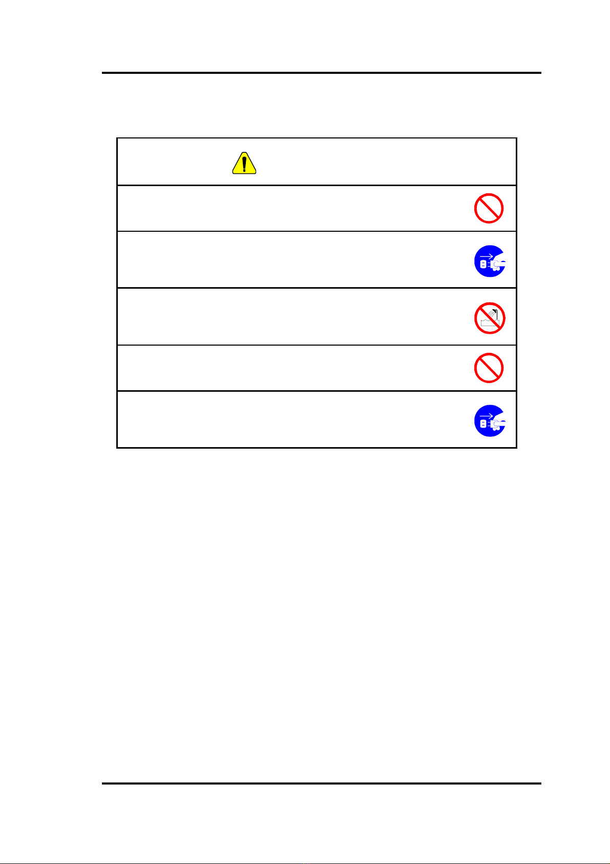
1.2 Important Safety Notes
Please read this page before using the product.
Use only the specified voltage.
Using the wrong voltage risks fire and electrical shock.
At the first signs of smoke, an unusual smell, or other problems,
unplug the emulator and disconnect all external power cords.
Continued use risks fire and electrical shock.
Do not use the product in an environment exposing it to moisture or
high humidity.
Such exposure risks fire and electrical shock
Do not pile objects on top of the product.
Such pressure risks fore and electrical shock.
At the first signs of breakdown, immediately stop using the product,
unplug the emulator, and disconnect all external power cords.
Continued use risks fire and electrical shock.
Warning
Chapter 1 Read Me First
Page 1-4
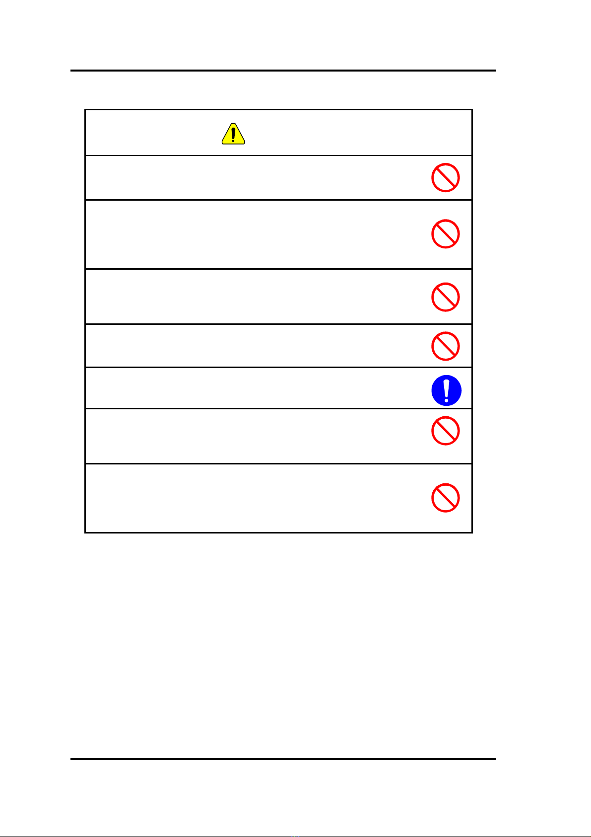
Please read this page before using the product.
Do not use this product on an unstable or inclined base as it can fall or
overturn, producing injury.
Do not use this product in an environment exposing it to excessive
vibration, strong magnetic fields, or corrosive gases.
Such factors can loosen or even disconnect cable connectors,
producing a breakdown.
Do not use this product in an environment exposing it to temperatures
outside the specified range, direct sunlight, or excessive dust.
Such factors risk fire and breakdown.
Use only the cables and other accessories provided.
Using non-compatible parts risks fire and breakdown.
Always observe the specified order for turning equipment on and off.
Using the incorrect order risks fire and breakdown.
Do not use the cables and other accessories provided with other
systems.
Such improper usage risks fire.
Before connecting or disconnecting the cables and the accessories,
the power source for the emulator must be turned OFF.
Connections or disconnections performed while the power source is
ON risk fire and damage to the system.
Caution

Chapter 1 Read Me First
Page 1-5
1.3 Notation
This manual utilizes the following notational conventions for convenience.
!Caution !A “caution” indicates a section of the manual that
requires special attention.
!Reference !A “reference” provides information related to the
current topic and indicates the page number of a
related section of the manual.
!Application Example !An “application example” indicates an example
related to the current topic.
(note ×)“(note ×)” is a reference to a numbered note that
provides supplementary information lower on the
same page.
!Note x !“Note ×:” provides supplementary information
related to the passage marked with “(note ×).”

Chapter 1 Read Me First
Page 1-6
1.4 For Further Information
Thank you for purchasing the Oki ML670100 CPU Board.
Please direct any questions or comments regarding this product to your Oki distributor or
the nearest Oki Electric Sales Office.
Table of contents
Other Oki Printer Accessories manuals


