Oki MC770 series User manual

MC770 / MC770+ / MC780 / MC780+
MB760dn / MB770dnf / B721dn / B731dn
MPS3537mc / MPS3537mc+
MPS4242mc / MPS4242mc+
LCF Unit
Maintenance Manual
102213A

Copyright Information
Copyright © 2013 by Oki Data. All Rights Reserved
Disclaimer
Every effort has been made to ensure that the information in this document is complete, accurate, and up-to-
date. The manufacturer assumes no responsibility for the results of errors beyond its control. The
manufacturer also cannot guarantee that changes in software and equipment made by other manufacturers and
referred to in this guide will not affect the applicability of the information in it. Mention of software products
manufactured by other companies does not necessarily constitute endorsement by the manufacturer.
While all reasonable efforts have been made to make this document as accurate and helpful as possible, we
make no warranty of any kind, expressed or implied, as to the accuracy or completeness of the information
contained herein.
The most up-to-date drivers and manuals are available from the web site:
http://www.okiprintingsolutions.com

45393301TH Rev.1 3 /
Oki Data CONFIDENTIAL
This manual explains the maintenance methods of LCF unit optionally installed in the MC760/
MC770/MC780/MB760dn/MB770dnf/B721dn/B731dn.
This manual is prepared for the maintenance person. In regard to the handling methods of
MC760/MC770/MC780/MB760dn/MB770dnf/B721dn/B731dn, please refer to the User’s
Manual.
Note! • Contentsofthismanualissubjecttochangewithoutnotice.
• While all reasonable efforts have been made to make this document
as accurate and helpful as possible, we make no warranty of any kind,
expressed or implied, as to the accuracy of the information contained
herein. Oki Data assumes no responsibility to the damages caused or
claimedtohavebeencausedbytheuserasaresultofrepair,adjustment
and/or change using this manual.
• Parts of this product are delicate and can be damaged unless properly
handled. We strongly recommend the user to maintain the product at the
hand of the registered maintenance person of our company
• Beforestartingthemaintenancework,pleaseneutralizethestaticelectricity.
PREFACE
PREFACE

Oki Data CONFIDENTIAL
1.
REPLACEMENT OF PARTS
This chapter describes the procedures of the field replacement of parts, assemblies and units. The procedures are to detach them. Reverse
the procedures to attach them.
The reference part numbers used in this manual (such as and ) do not identical to the part numbers in the maintenance disassembly
configuration diagram (45393301TL) and RSPL (45393301TR) for the manual.
1.1 Notes on replacement of parts ........................................................5
1.2 Part replacement procedure............................................................7

45393301TH Rev.1 5 /
Oki Data CONFIDENTIAL 1.REPLACEMENT OF PARTS
1.1 Notes on replacement of parts
(1) Prior to replacing a part, unplug the AC cord and the interface cable.
(a) Be sure to use the following procedure to unplug the AC cord:
Turn off the printer [the power switch to the off (O) position].
Pull out the AC plug of the AC cord from the AC power source.
Unplug the AC cord and the interface cable.
(2) Do not disassemble the printer so long as it operates properly.
(3) Minimize disassembly. Do not detach parts not shown in the part replacement
procedure.
(4) Use the replacement tools specified.
(5) Conduct disassembly in the order instructed, or part damage may occur.
(6) Removed small parts, such as screws or collars, should be tentatively installed in
their original positions.
(7) Do not use static-prone gloves when handling integrated circuits (ICs), including
microprocessors, and ROM and RAM chips, or circuit boards.
(8) Do not place printed-circuit boards (PCBs) directly on the printer or a floor.
Remo
ve
Install
(b) Always use the following procedure to reconnect the printer:
Connect the AC cord and the interface cable to the printer.
Insert the AC plug into the AC power source.
Turn on the printer [the power switch to the on (I) position].
Warning
Electric shock hazard
When replacing the low-voltage power supply, electric shock may occur. Wear insulated
gloves, or be careful not to touch the conductors or terminals of the power supply directly.
After the AC cord is unplugged, the capacitor may take about one minute to discharge
completely or, due to PCB breakdown, could not discharge. Use caution about electric shock.

45393301TH Rev.1 6 /
Oki Data CONFIDENTIAL 1.REPLACEMENT OF PARTS
Maintenance Tools:
Table 1-1-1 shows the tools necessary to replace printed-circuit boards and units:
Table 1-1-1: Maintenance Tools
No. Maintenance Tool Quantity Use Remarks
1
Phillips
screwdriver with
magnetic tip, No.
2-200
13- to 5-mm
screws
2Screwdriver No.
3-100 1
3Digital multimeter 1
4Pliers 1
5E-ring pliers 1 E-shaped ring
removal

45393301TH Rev.1 7 /
Oki Data CONFIDENTIAL 1.REPLACEMENT OF PARTS
1.2 Part replacement procedure
This section describes the procedure for replacing the parts and assemblies shown in the
disassembly diagrams below.
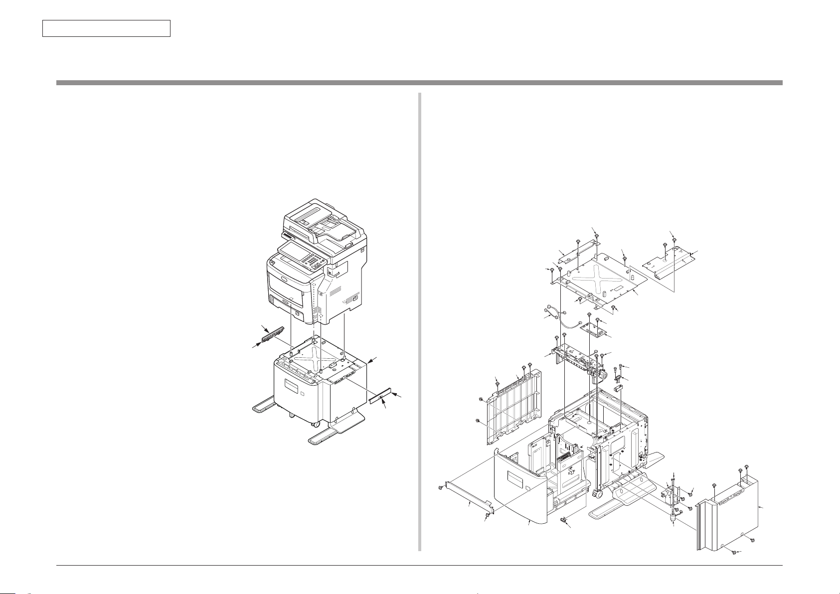
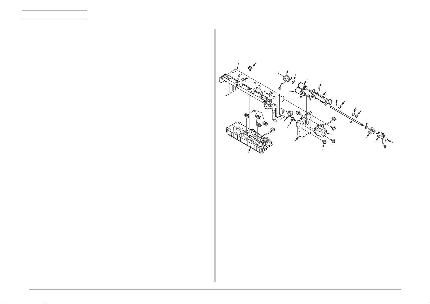
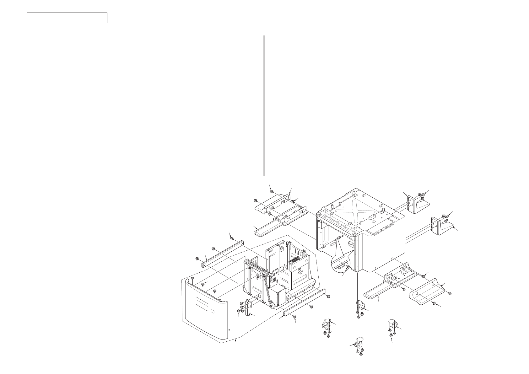
1.2.1 Board-GOI,Frame.Assy-Hop etc
(1) Remove the Screw (silver,No:41723901) ①and remove the Joint ②(2 places),and
remove the LCF Unit ③from the MFP.
(This procedure unnecessary for B721/B731)
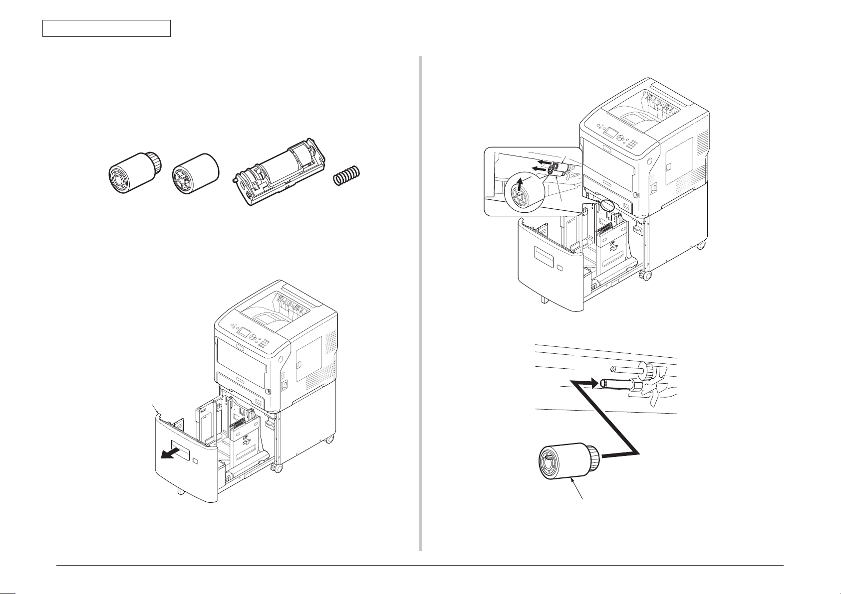
(2) Draw out the Cassette ④from LCF Unit.
④
⑦
⑧×2
⑨⑩
⑬
⑪
⑪
⑪
⑭
⑤×5
⑧
×2
⑫
⑫
⑮⑯×2
⑲×4
⑳㉑×2
㉒
⑥
⑤×5
㉓
㉖×2
㉗
㉔×4
㉕
⑰×2
⑱
①
①
②
②
③
(3) Remove the ten screws (silver,No:42920408) ⑤and remove the Cover-
Side(L) ⑥,Cover-Side(R) ⑦.
(If the LCF for B721/B731, remove the four screws)
(4) Remove the four screws (silver,No:42920408) ⑧and remove the Plate-
Joint(L) ⑨,Plate-Joint(R) ⑩.
(This procedure unnecessary for B721/B731)
(5) Remove the three screws (silver,No:42920406) ⑪and two screws
(black,No:44883906) ⑫and remove the Plate-Top ⑬.
(If the LCF for B721/B731, remove the seven screws (silver,No:42920406) and two
screws (black,No:44883906))
(6) Remove all cables ⑮and connectors from the Board ⑭.
(7) Remove the two screws (black,No:44883906) ⑯and remove the Board-GOI ⑭.
(8) Remove the two screws (silver,No:42920406) ⑰and remove the Plate-Front ⑱.
(9) Remove the four screws (black,No:44883906) ⑲and remove the Frame.Assy-
Hop ⑳.
(10) Remove the two screws (silver,No:43497603) and remove the Connector .
(11) Remove the Claw and remove the Switch .
(12) Remove the four screws (black,No:44883906) and remove the Liftup-Motor-
Assy . Remove the two screws(silver,PSW2W2.6-5C)and remove the motor .

45393301TH Rev.1 8 /
Oki Data CONFIDENTIAL 1.REPLACEMENT OF PARTS
1.2.2 Photo sensor
(1) Remove the Frame.Assy-Hop(See 1.2.1)
(2) Remove the E-ring ①and remove the Hopping Clutch ②.
(3) Remove the three screws (silver,No:42920406) ③and remove the Plate-Assy-
Motor ④.
(4) Remove the two screws (silver,No:42920406) ⑤and remove the Motor ⑥.
(5) Remove the Gear-Z21-56 ⑦and Gear-Hopping ⑧and Bearing-Metal ⑨.
(6) Remove the Hopping roller ⑩and Pickup roller ⑪.
(7) Remove the two E-ring ⑫and pin ⑬and Gear-Feed ⑭.
(8) Remove the Bearing-Metal ⑮and Bush ⑯and remove the shaft ⑰.
(9) Remove the Frame-Assy-Pickup ⑱.(Pay attention to spring to lose)
(10) Remove the screw (Black,No:42932708) ⑲and remove the Plate-Hopping ⑳.
(11) Remove the claw and remove the photo sensor .(Four places)
(12) Remove the E-ring and remove the Regist Clutch .
【Attention for assembling】
・
Wiring the white cable of the photo sensor to the mark ”W”of Guide-Hop.
・When assembling the regist Clutch, same position the notch of the clutch and
bulge of the Plate-Motor.
・
Wiring the cable of the Hopping clutch(Black cable) to the mark ”BK”of Plate-Motor.
When assembling the Hopping Clutch, same position the notch of the clutch and
bulge of the Plate-Motor.
・When assembling the Motor, four emboss put into hole of Plate-Motor.The direction
of the Motor Cable should ” ↑”mark of Plate-Motor.
・To check the three claws and two claws of is hold by ⑳.
㉑
③×3
②
①
⑲
⑳
④⑧
⑦⑰
⑨
⑪
⑩⑫
⑫
⑬
⑱
⑮
⑭
⑯
⑤×2 ⑥
㉒
㉓
㉔
spring

45393301TH Rev.1 9 /
Oki Data CONFIDENTIAL 1.REPLACEMENT OF PARTS
①
②×3
②×3
④
④
⑦×4 ⑧
⑨×1 2
⑪
⑩
⑪
⑩
⑫×2
⑬
⑫
×2 ⑬
⑭×2
⑮
⑭×2
⑮
⑯×3
⑯×3
⑰
⑰
⑤×3
⑥
③×6
1.2.3 Caster etc
(1) Draw out the Casstte ①,remove the six screws
(silver, D4-6HH)② and remove
the Cassette ①from LCF Unit.
(2) Remove the six screws
(silver, D4-6HH)③ and remove the Slide-Rail ④.
(2 places)
(3) Remove the three screws
(silver, No:42920406)⑤ and remove the Cover-
Front(LCF) ⑥.
(4) Remove the four screws
(silver, No:42920406)⑦ and Caster-Assy-Tray ⑧.
(5) Remove the twelve screws
(silver, No:42937208)⑨ and remove the two
Casters(with lock) ⑩ and remove the two Casters(without lock) ⑪. (Pay attention
to the position of caster, when assembling.)
(6) Remove the four screws
(silver, No:42937210)⑫ and remove the Cover-Leg-
Side ⑬.(2 places)
(7) Remove the four screws
(silver, No:42937210)⑭ and remove the Plate-Leg-
Assy ⑮.(2 places)
(8) Remove the six screws
(silver, No:42937210)⑯ and remove the Leg-Rear ⑰.
(2 places)

45393301TH Rev.1 10 /
Oki Data CONFIDENTIAL 1.REPLACEMENT OF PARTS
1.2.4 Pickup roller
If the hopping jam occurs frequently, to change the pickup roller and separation roller.
Model name: RS-C4B
separation roller spring
feed roler
(with gear)
pickup roler
(without gear)
Notes! •Ifchangetheroller,tochangeallrollers.
(1) Draw out the paper tray after the power off the printer.
P
aper Cassette
(2) Remove the latch and remove the roller ①,②
②
①
(3) Put the new roller
(with gear)① to the shaft.
①

45393301TH Rev.1 11 /
Oki Data CONFIDENTIAL 1.REPLACEMENT OF PARTS
(4) Put the new roller
(with gear)② to the shaft.
②
(5) Check the roller.
(6) Push the claws of cover and open the cover.
Tab Cover
Tab
③
(7) Remove the Retard Roller ③and spring ④.
③
④
(8) Assemble the spring ④to the new Reatard Roller ③.
③
④
(9) Set the spring ④of the Reatard Roller ③to the mark of the cassette.
③
④

45393301TH Rev.112 / 12
Oki Data CONFIDENTIAL 1.REPLACEMENT OF PARTS
(10)Set the position groove of Retard Roller ③to boss of Cassette.
Notes! Don't assemble the groove and boss this procedure.
(13) To p u s h a r o u n d t h e c o v e r, and check the Retard Roller moving up and down.
Cassette
boss
groove ③
(11) Assemble the Retard Roller ③to push the Retard Roller ③to Cassette, and push
up front side.
Cassette
boss
groove
③
(12) Close the Cover.
Notes!To assemble again, if the cover cannot close.
Cover
Claw
Claw
(14) Return to the cassette to LCF.
Other manuals for MC770 series
2
This manual suits for next models
8
Table of contents
Other Oki Printer Accessories manuals