Oki B4100 User manual

Oki Data CONFIDENTIAL
123456
Rev Date DCO No. Contents Design Approval
BOM Use for Certification Body
Approval
Check
Date Drawing No.
Name
Design
.....................................................................................................
.....................................................................................................
B4100
Monochrome LED Page Printer
Maintenance Manual
ODA
040623A
No.01
42640901TH
B4100
Maintenance Manual
186
2004-04-14
Hisao Ono Hisao Ono

42640901TH Rev.1 2 /
Oki Data CONFIDENTIAL
1 2004-04-01 ISSUE ME5 Ono
Rev.No. Date No.
Corrected items
Page Description of change Person in
charge
Document Revision History

42640901TH Rev.1 3 /
Oki Data CONFIDENTIAL
PREFACE
This Maintenance Manual describes the field maintenance methods for B4100 Monochrome LED Page
Printers.
This manual is written for use by service persons. Please note that you should refer to the Printer Handbook
for the handling and operating methods of the equipment.

42640901TH Rev.1 4 /
Oki Data CONFIDENTIAL
CONTENTS
1. CONFIGURATION.................................................................................................... 6
1.1 System Configuration ....................................................................................... 6
1.2 Printer Configuration......................................................................................... 7
1.3 Specification ..................................................................................................... 8
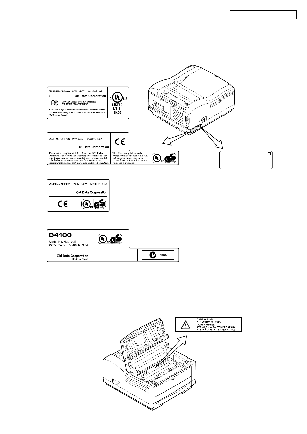
1.4 Safety Standards ............................................................................................ 10
1.4.1 Certification Label...................................................................................................... 10
1.4.2 Warning Label ........................................................................................................... 10
1.4.3 Warning/Caution Marking .......................................................................................... 11
2. PARTS REPLACEMENT........................................................................................ 12
2.1 Precautions for Parts Replacement................................................................ 12
2.2 Parts Layout.................................................................................................... 14
2.3 How to Change Parts...................................................................................... 17
2.3.1 Upper Cover Assy ..................................................................................................... 18
2.3.2 LED Head .................................................................................................................. 19
2.3.3 Operator Panel Assy ................................................................................................. 20
2.3.4 Lower Base Unit ........................................................................................................ 21
2.3.5 Pulse Motor (Main/Drum) .......................................................................................... 22
2.3.6 Pulse Motor (Registration)......................................................................................... 23
2.3.7 Face Up Stacker Assy ............................................................................................... 24
2.3.8 Eject Roller Assy ....................................................................................................... 25
2.3.9 Motor Assy.................................................................................................................26
2.3.10 Hopping Roller Shaft Assy......................................................................................... 27
2.3.11 Stacker Cover Assy ................................................................................................... 28
2.3.12 Registration Roller ..................................................................................................... 29
2.3.13 Roller Transfer Assy .................................................................................................. 30
2.3.14 Fusing Unit ................................................................................................................ 31
2.3.15 Back-up Roller ........................................................................................................... 32
2.3.16 Sensor Plate (Inlet).................................................................................................... 33
2.3.17 Sensor Plate (Outlet), Sensor Wire Assy .................................................................. 34
2.3.18 Manual Feed Guide Assy .......................................................................................... 35
2.3.19 Sensor Plate (Paper Supply) ..................................................................................... 36
2.3.20 GRG-5, 7 PCB........................................................................................................... 37
2.3.21 Power Supply Board and High Voltage/Sensor Board .............................................. 38
2.3.22 Cassette Guide L Assy .............................................................................................. 39
2.3.23 Cassette Guide R Assy ............................................................................................. 40
3. ADJUSTMENT........................................................................................................ 41
3.1 Adjustment Types and Functions ................................................................... 41
3.1.1 Status Monitor ........................................................................................................... 41
3.1.2 Maintenance Utility .................................................................................................... 41
3.2 Adjustment When Replacing a Part................................................................ 41
3.2.1 Uploading/Downloading EEPROM data .................................................................... 41
4. PERIODICAL MAINTENANCE .............................................................................. 42
4.1 Periodical Replacement Parts ........................................................................ 42
4.2 Cleaning.......................................................................................................... 42
4.2.1 Cleaning of LED Lens Array ...................................................................................... 42
4.2.2 Cleaning Page Function ............................................................................................ 43

42640901TH Rev.1 5 /
Oki Data CONFIDENTIAL
5. TROUBLESHOOTING PROCEDURES ................................................................. 44
5.1 Troubleshooting Tips ...................................................................................... 44
5.2 Check Points Before Correcting Image Problems .......................................... 44
5.3 Notes When Correcting Image Problems ....................................................... 44
5.4 Preparation Before Troubleshooting............................................................... 44
5.5 Troubleshooting.............................................................................................. 47
5.5.1 Status Monitor Message List ..................................................................................... 47
5.5.2 Status Message Troubleshooting .............................................................................. 51
5.5.3 Image Troubleshooting.............................................................................................. 58
6. WIRING DIAGRAM................................................................................................ 67
6.1 Interconnect Signal Diagram .......................................................................... 67
6.2 PCB Layout and Connector Signal List .......................................................... 68
6.3 Resistance Check........................................................................................... 75
APPENDIX A CENTRONICS PARALLEL INTERFACE (ODA230V/OEL/AOS ONLY) .... 77
APPENDIX B UNIVERSAL SERIAL BUS (USB)....................................................... 83

42640901TH Rev.1 6 /
Oki Data CONFIDENTIAL
1. CONFIGURATION
1.1 System Configuration
B4100 consists of control and engine blocks in the standard configuration, as shown in Figure 1-1.
Figure 1-1
Operrator Panel LED : 4
SW : 1
Drum
Motor
Paper
Cassette
ID
Unit
Paper Feeding
Mechanism
(First Tray Unit)
Hopping/
Registration
Motor
LED Head
Electrophotogarphic
Processing Unit
Fuser Unit
Halogen-Lamp
High Voltage Unit
and Sensor Board
IEEE1284
(ODA230V/OEL/AOS)
USB
AC
INPUT
Power Supply
Board
Face Down
Stacker
FAN
Main Control Board

42640901TH Rev.1 7 /
Oki Data CONFIDENTIAL
1.2 Printer Configuration
The printer unit consists of the following hardware components:
• Electrophotographic Processor
• Paper Feeder
• Controller
• Operator Panel
• Power Supply Unit
The printer unit configuration is shown in Figure 1-2.
Figure 1-2
Upper cover
Operator panel assy
Stacker assy
Legal/universal paper cassette
Image drum unit(Type9)
(consumable)
Toner-cartridge(Type9)
(consumable)
Power supply
High Voltage / sensor board
Main control board

42640901TH Rev.1 8 /
Oki Data CONFIDENTIAL
1.3 Specification
(1) Type Desktop
(2) External dimensions Height 7.9”(200 mm)
Width 14.0”(355 mm)
Depth 15.7”(400 mm)
(3) Weight Approx. 9 kg
(4) Developing method Dry electrophotography
Exposing method LED stationary head
(5) Paper used <Type>
•Standard paper
–Xerox 4200 (20 lbs)
•Application paper (manual face-up feed)
–Label
–Envelope
–OHP paper (transparency)
<Size>
•Standard sizes
–Letter
–Legal
–Legal-13
–Executive
–COM-9 *
–COM-10* [* Manual feed only]
–Monarch*
–DL*
–C5*
–A4
–A5
–B5 (JIS)
–A6
•Applicable sizes
–Width : 3.5”to 8.5”(90 to 216 mm)
–Length : 5.8”to 14”(148 to 355.6 mm)
<Thickness>
–Automatic feed : 16 to 28 lbs (60 to 105 g/m2)
–Manual feed : Label, OHP paper (transparency)
Envelope (24 to 28 lbs)
(6) Printing speed Continuous printing : 19 pages per minute with Letter size paper.
18 pages per minute with A4 size paper.
Warm-up time : 35 seconds typical at room temperature
[68˚F (20˚C), AC 120/230 V].
First page print time : 6.0 seconds typical for the Letter size paper
(6.2 seconds for the A4 size) after warm-up.
(7) Paper feeding method Automatic feed or manual feed
(8) Paper delivery method Face down/face up
(9) Resolution 600 ×600 dots/inch
600 ×1200 dots/inch

42640901TH Rev.1 9 /
Oki Data CONFIDENTIAL
(10)Power input 110~127 VAC ±10%
220~240 VAC ±10%
(11)Power consumption 120VAC 230VAC
Peak : Approx. 700W Approx. 700W
Typical operation : Approx. 340W Approx. 350W
Idle : Approx. 66W Approx. 68W
Power save mode : Approx. 8W Approx. 9W
(12) Temperature and humidity
1. Storage conditions specified above apply to printers in packed condition.
2. Temperature and humidity must be in the range where no condensation occurs.
In operation Power off mode During Storage Unit
Temperature
Humidity
Maximum wet bulb
temperature
Minimum diference
between wet and dry
bulb temperatures
50-90
(10-32)
20-80
77
(25)
35.6
(2)
°F
(°C)
%RH
°F
(°C)
°F
(°C)
32-110
(0-43)
10-90
80.4
(26.8)
35.6
(2)
14-110
(–10-43)
10-90
(13) Noise During operation : 53 dB (A) or less
Standby : 38 dB (A) or less
Quiet mode : Back ground level
(14) Consumables Toner cartridge kit 2,500 (5% duty)
Image drum cartridge 25,000 (at continuouts printing)
17,000 (3 page/job) without Power Save
11,000 (1 page/job) without Power Save
7,000 (1 page/job) with Power Save
(Minimum)
10
28
32
Temperature
(
°
C)
20 80 Humidity (%)
Operation range

42640901TH Rev.1 10 /
Oki Data CONFIDENTIAL
1.4 Safety Standards
1.4.1 Certification Label
The safety certification label is affixed to the printer in the position described below.
1.4.2 Warning Label
The warning labels are affixed to the sections which may cause bodily injury.
Follow the instructions on warning labels during maintenance.
Serial No.
Made In China
ODA AC : 120V model
ODA AC : 230V model
OEL AC : 230V model
AOS AC : 230V model

42640901TH Rev.1 11 /
Oki Data CONFIDENTIAL
1.4.3 Warning/Caution Marking
The following warning and caution markings are made on the power supply/sensor board.
ENGLISH
Heatsink and transformer core present risk of electric shock. Test before touching.
CAUTION

42640901TH Rev.1 12 /
Oki Data CONFIDENTIAL
2. PARTS REPLACEMENT
The section explains the procedures for replacement of parts, assemblies, and units in the field. Only
the disassembly procedures are explained here. For reassembly, reverse the disassembly procedure.
2.1 Precautions for Parts Replacement
(1) Before starting to replace parts, remove the AC cord and interface cable.
(a) Remove the AC cord in the following sequence:
i) Turn off (“o”) the power switch of the printer
ii) Disconnect the AC inlet plug of the AC cord from the AC receptacle.
iii) Disconnect the AC cord and interface cable from the printer.
(b) Reconnect the printer in the following procedure.
i) Connect the AC cord and interface cable to the printer.
ii) Connect the AC inlet plug to the AC receptacle.
iii) Turn on (“l”) the power switch of the printer.
(2) Do not disassemble the printer as long as it is operating normally.
(3) Do not remove parts which do not have to be touched; try to keep the disassembly to a minimum.
(4) Use specified service tools.
(5) Whendisassembling,followthelaidoutsequences.Partsmaybedamagedifthesesequencesare
not followed.
(6) Sincescrews,collars andothersmallpartsarelikelytobelost,theyshouldtemporarilybe attached
to the original positions during disassembly.
(7) When handling IC’s such as microprocessors, ROMs and RAMs, or circuit boards, do not wear
gloves that are likely to generate static electricity.
(8) Do not place printed circuit boards directly on the equipment or floor.
Disconnect
Reconnect
OFF
ON

42640901TH Rev.1 13 /
Oki Data CONFIDENTIAL
[Service Tools]
Thetoolsrequiredforfieldreplacementofprintedcircuitboards,assemblies andunitsarelistedinTable
2-1.
Table 2-1 Service Tools
No. Q’ty Application RemarksService Tools
1
2
3
4
5
6
7
8
1
1
1
1
1
1
1
1
2~2.5 mm screws
3~5 mm screws
Cleans LED head
No. 1-100 Philips screwdriver
No. 2-100 Philips screwdriver
No. 3-100 screwdriver
No. 5-200 screwdriver
Digital multimeter
Pliers
Handy cleaner
LED Head cleaner

42640901TH Rev.1 14 /
Oki Data CONFIDENTIAL
2.2 Parts Layout
This section explains the layout of main components of the equipment.
[Lower base unit]
Figure 2-1
Fusing unit
Image drum unit (Type 9)
(consumable)
Toner cartridge (Type 9)
(consumable)
LED head
Stacker cover assy
View A
Pulse motor
(main/drum)
Pulse motor
(registration)
Stacker cover assy
Eject roller assy
Registration
roller Assy
Back-up roller
Diselectrification bar
Transfer roller
Lower base unit
Hopping roller rubber
Hopping roller shaft
Manual feed guide assy
View A

42640901TH Rev.1 15 /
Oki Data CONFIDENTIAL
[Upper cover unit]
Figure 2-2
Upper cover

42640901TH Rev.1 16 /
Oki Data CONFIDENTIAL
[Base unit]
Figure 2-3
Paper cassette
Cassette guide (L) Assy
Cassette guide (R) Assy
DC fan assy
Face up stacker assy
Operator panel assy
Power supply board
(Low voltage)
High voltage /
sensor board
Main control board

42640901TH Rev.1 17 /
Oki Data CONFIDENTIAL
2.3 How to Change Parts
This section explains how to change parts and assemblies listed in the disassembly diagram below.
Inthe parts replacement procedure,thosepartsmarked with the partnumberinside●with white letters
are RSPL parts.
Printer unit Upper cover assy
(2.3.1)
LED head
(2.3.2)
Transfer roller
(2.3.13)
Face up stacker assy
(2.3.7)
Lower base unit
(2.3.4)
Operator panel assy
(2.3.3)
Manual feed guide assy
(2.3.18) Pulse motor (main/drum)
(2.3.5)
Pulse motor (registration)
(2.3.6)
Eject roller assy
(2.3.8)
Motor assy
(2.3.9)
Sensor plate (inlet)
(2.3.16)
Sensor plate (outlet),
sensor wire assy
(2.3.17)
Sensor plate (paper supply)
(2.3.19)
GRG-5,7 PCB
(2.3.20)
1
Hopping roller shaft assy
(2.3.10)
Stacker cover assy
(2.3.11)
Registration roller
(2.3.12)
Fusing unit
(2.3.14) Back up roller
(2.3.15)
2
Power supply/sensor board,high voltage unit
(2.3.21) Cassette guide (L)
(2.3.22)
Cassette guide (R)
(2.3.23)
To
1
To
2

42640901TH Rev.1 18 /
Oki Data CONFIDENTIAL
2.3.1 Upper Cover Assy
(1) With the power switch turned off, unplug the AC power cord from the outlet.
(2) Disconnect the interface cable 1.
(3) Press the button 2on right side of the Upper cover and open the stacker cover assy 3.
(4) Take out the image drum unit 4.
(5) Open the manual feed guide assy 5. Unlock the latches at two locations on the front side. Lift the
frontside oftheupper cover6up andunlock the latchesat two locationson thebackside. Lift and
remove the upper cover assy 6.
Note :
When removing or reinstalling the upper cover, be careful not to get the motor cables tangled
or caught.
LATCH
LATCH
5
6
3
4
1
2

42640901TH Rev.1 19 /
Oki Data CONFIDENTIAL
2.3.2 LED Head
(1) Press the button on right side of the upper cover and open the stacker cover assy 1.
(2) Open the hook section on the left side of the head holder and remove the LED head 2.
(3) Remove the head cable 3from the head connector.
Note:
Be sure not to touch directly or push on the SLA part of the LED head.
1
2
3
SLA
(Seltoc Lens Array)

42640901TH Rev.1 20 /
Oki Data CONFIDENTIAL
2.3.3 Operator Panel Assy
(1) Unlock two latches on the upper cover from the rear side, lift the operator panel assy 1from the
back and remove it.
(2) Remove the Sumi card (operator panel) 2from the connector (CN1) 3.
Note :
Youcan remove the operatorpanelassy while the uppercoverinstalled on the unit. However,
it is much easier to remove the panel assy after removal of upper cover.
Unlock two latches with a tip of
screw driver. For the purpose,
insert a driver through faceup
paper outlet as shown.
Rear view
2
1
3
Other manuals for B4100
12
Table of contents
Other Oki Printer manuals

Oki
Oki B710n Quick start guide

Oki
Oki es7120 User manual

Oki
Oki C130n User manual

Oki
Oki ML6300FB Owner's manual

Oki
Oki C 9650dn User manual

Oki
Oki ML3410 User manual

Oki
Oki C711WT Quick start guide

Oki
Oki C8800dn User manual

Oki
Oki C3300n Installation and maintenance instructions

Oki
Oki PAGE 14ex User manual

Oki
Oki ML320 Epson/IBM User manual

Oki
Oki B4400 Series User manual

Oki
Oki C110 Specification sheet

Oki
Oki C6000dn Service manual

Oki
Oki ES1624n MFP Instruction Manual

Oki
Oki B710dn Operating and maintenance instructions

Oki
Oki B930d User manual

Oki
Oki 10i User manual

Oki
Oki C6100 Series User manual

Oki
Oki C5400 Series User manual