40718301TH Rev.6 2 /
CONTENTS
1. CONFIGURATION.................................................................................................. 5
1.1 System Configuration ..................................................................................... 5
1.2 Printer Configuration....................................................................................... 7
1.3 Optional Configuration.................................................................................... 8
1.4 Specification ................................................................................................... 11
1.5 Safety Standards ............................................................................................ 13
1.5.1 Certification Label................................................................................................... 13
1.5.2 Warning Label ........................................................................................................ 13
1.5.3 Warning/Caution Marking....................................................................................... 14
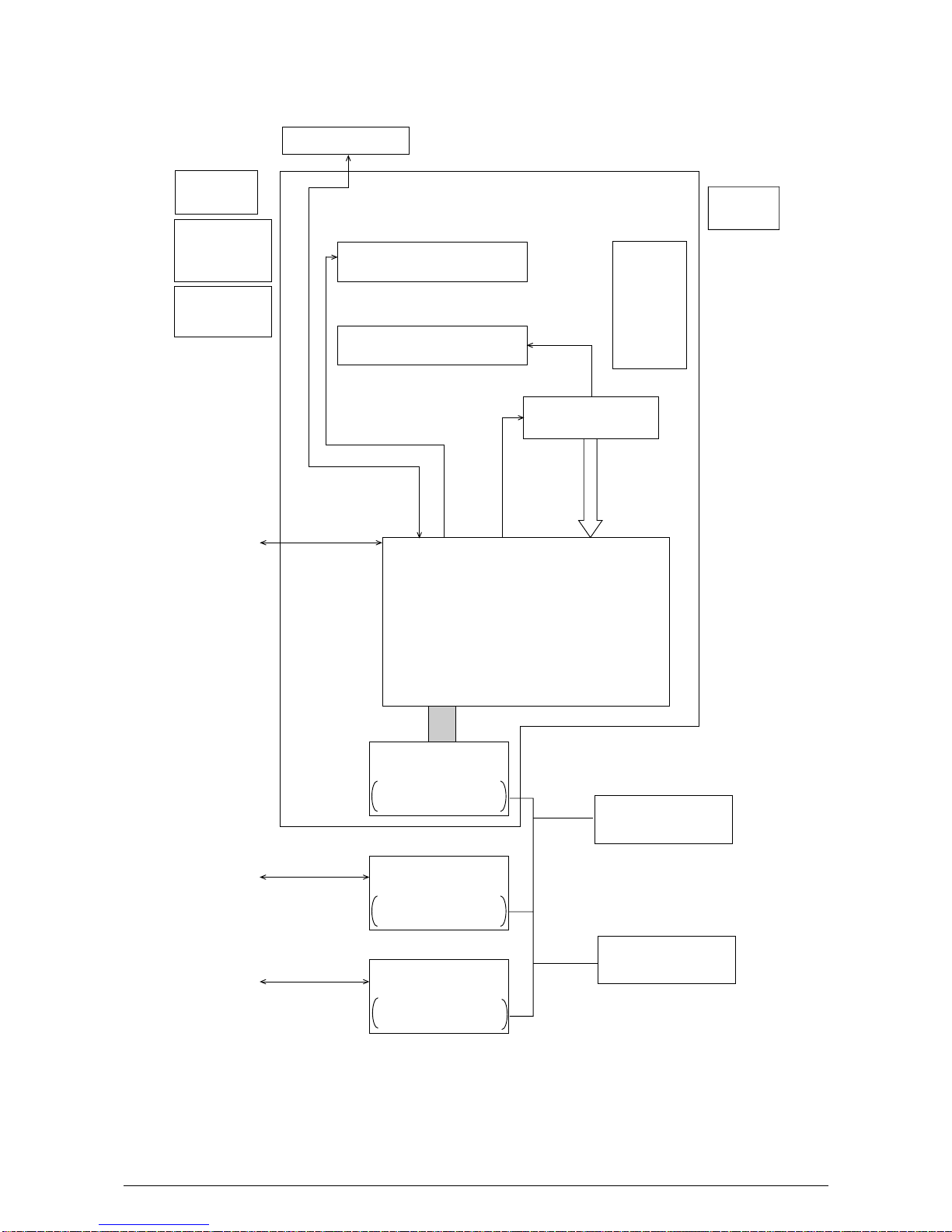
2. OPERATION DESCRIPTION ................................................................................. 15
2.1 Main Control Board......................................................................................... 17
2.2 Power Supply/Sensor Board........................................................................... 18
2.3 Electrophotographic Process.......................................................................... 20
2.3.1 Electrophotographic Process Mechanism .............................................................. 20
2.3.2 Electrophotographic Process ................................................................................. 23
2.3.3 Process Operation Descriptions............................................................................. 26
2.3.4 Revision of LED Head Illumination36
2.4 Paper Jam Detection ...................................................................................... 40
2.5 Cover Open .................................................................................................... 42
2.6 Toner Low Detection....................................................................................... 43
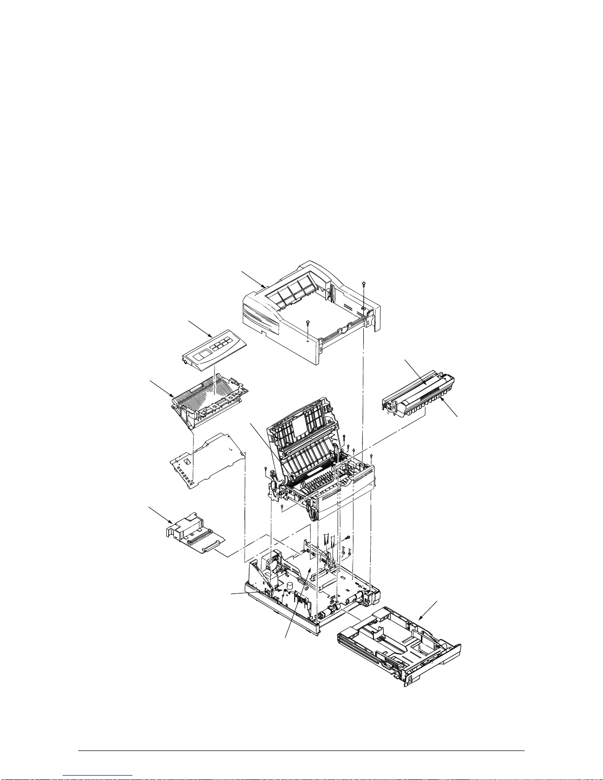
3. PARTS REPLACEMENT........................................................................................ 45
3.1 Precautions for Parts Replacement................................................................ 45
3.2 Parts Layout.................................................................................................... 47
3.3 How to Change Parts...................................................................................... 50
3.3.1 Upper Cover Assy .................................................................................................. 51
3.3.2 LED Head............................................................................................................... 52
3.3.3 Operator Panel Assy .............................................................................................. 53
3.3.4 Lower Base Unit ..................................................................................................... 54
3.3.5 Pulse Motor (Main/Drum) ....................................................................................... 55
3.3.6 Pulse Motor (Registration)...................................................................................... 56
3.3.7 Face Up Stacker Assy............................................................................................ 57
3.3.8 Eject Roller Assy .................................................................................................... 58
3.3.9 Motor Assy ............................................................................................................. 59
3.3.10 Hopping Roller Shaft Assy ..................................................................................... 60
3.3.11 Stacker Cover Assy................................................................................................ 61
3.3.12 Registration Roller.................................................................................................. 62
3.3.13 Roller Transfer Assy............................................................................................... 63
3.3.14 Fusing Unit ............................................................................................................. 64
3.3.15 Back-up Roller........................................................................................................ 65
3.3.16 Sensor Plate (Inlet)................................................................................................. 66
3.3.17 Sensor Plate (Outlet).............................................................................................. 67
3.3.18 Manual Feed Guide Assy ....................................................................................... 68
3.3.19 Sensor Plate (Paper Supply).................................................................................. 69
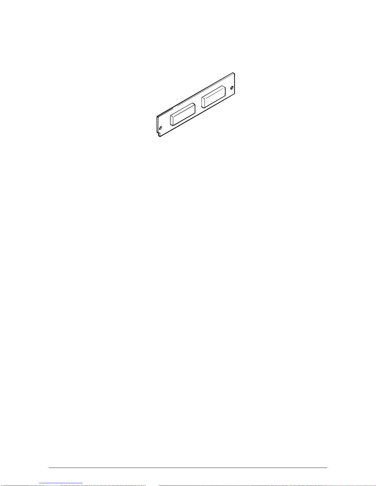
3.3.20 M5E-PCB ............................................................................................................... 70
3.3.21 Transformer............................................................................................................ 71
3.3.22 Power Supply/Sensor Board and Contact Assy ..................................................... 72
3.3.23 Cassette Guide L Assy........................................................................................... 73
3.3.24 Cassette Guide R Assy .......................................................................................... 74
3.3.25 Spacer Bearing (L/R).............................................................................................. 75