Oki PACEMARK 4410 User manual

40496501TH Rev.1 1 / 214
PACEMARK4410/
MICROLINE 4410
PRINTER
MAINTENANCE MANUAL
ODA/OEL/INT
1999. 3. 26 Rev.1

40496501TH Rev.1 2 /
Rev.No. Date Corrected items Person in
No. Page Description of change change

40496501TH Rev.1 3 /
PREFACE
This maintenance manual describes how to maintain the Pacemark 4410/Microline 4410 printer
in the field.
This manual is for customer engineers.
For further information, refer to the Users Manual for handling or operating the equipment.

40496501TH Rev.1 4 /
CONTENTS
1. CONFIGURATION ..................................................................................... 6
1.1 Basic System Configuration............................................................... 6
1.2 Printer Specifications......................................................................... 7
1.3 Option Specifications......................................................................... 8
1.4 Basic Specifications........................................................................... 9
2. THEORY OF OPERATION ........................................................................ 12
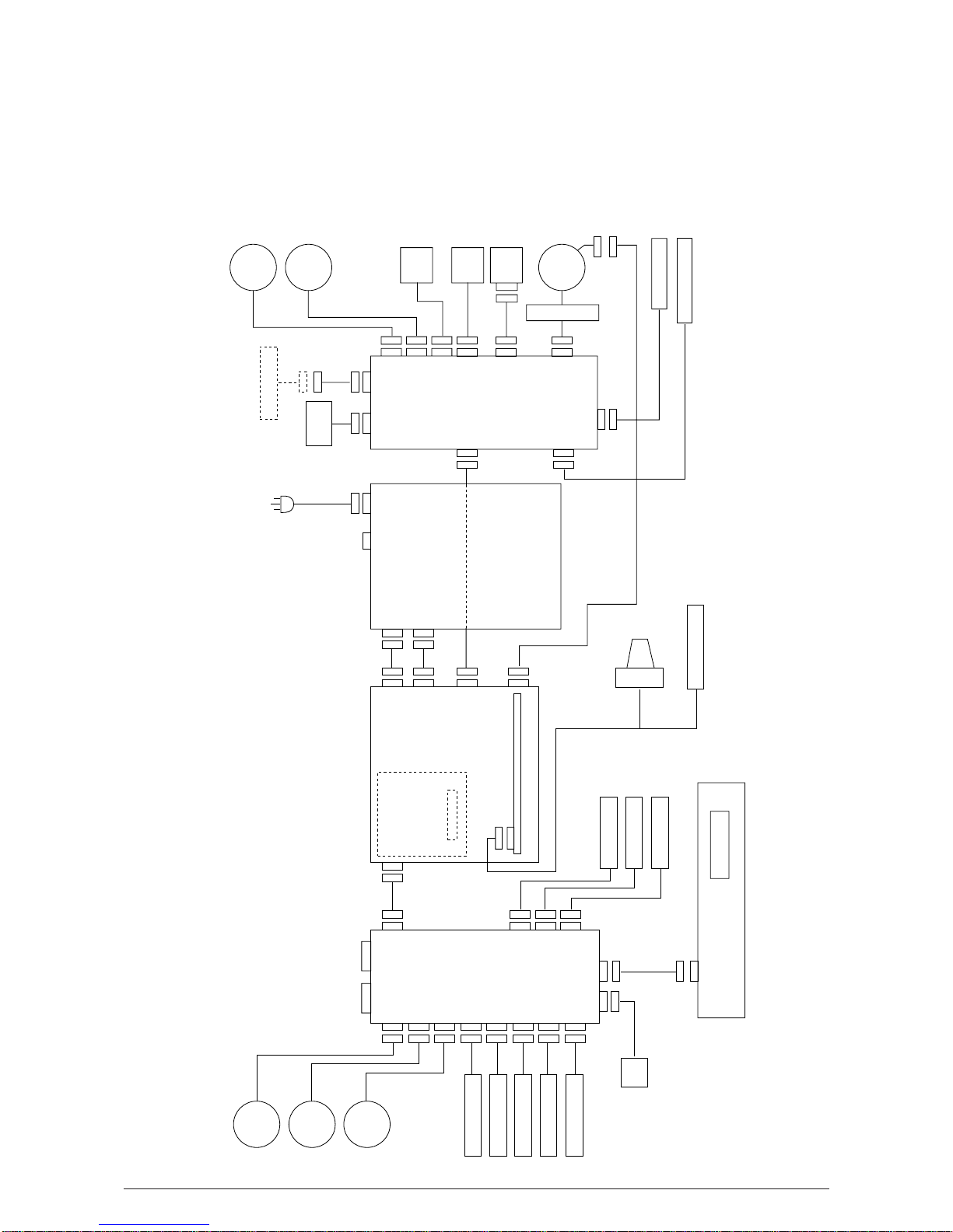
2.1 Electrical Operation ........................................................................... 12
2.1.1 Summary ................................................................................................. 12
2.1.2 Microprocessor and the peripheral circuit ............................................... 12
2.1.3 Initialization.............................................................................................. 21
2.1.4 Interface control....................................................................................... 22
2.1.5 Parallel Interface Control .........................................................................22
2.1.6 Serial Interface ........................................................................................ 23
2.1.7 Printing operation .................................................................................... 24
2.1.8 Printhead control ..................................................................................... 25
2.1.9 Print Compensation Control .................................................................... 27
2.1.10 Space motor control ................................................................................27
2.1.11 Line feed.................................................................................................. 28
2.1.12 Bail, tractor switching, AG, ribbon motor control .....................................29
2.1.13 Operation Panel ...................................................................................... 30
2.1.14 Alarm circuits ...........................................................................................32
2.1.15 Power supply circuit ................................................................................34
2.2 Mechanical Operation........................................................................ 35
2.2.1 Printhead mechanism and operation (See Figure 2-13) ......................... 35
2.2.2 Spacing operation (See Figure.2-15) ...................................................... 37
2.2.3 Head gap adjusting ................................................................................. 38
2.2.4 Ribbon drive (See Figure) .......................................................................41
2.2.5 Paper Feed Mechanism .......................................................................... 42
2.2.6 Bail Feed Mechanism (See Figure ) ........................................................ 46
2.2.7 Paper End Detection Mechanism (See Figure ) .....................................48
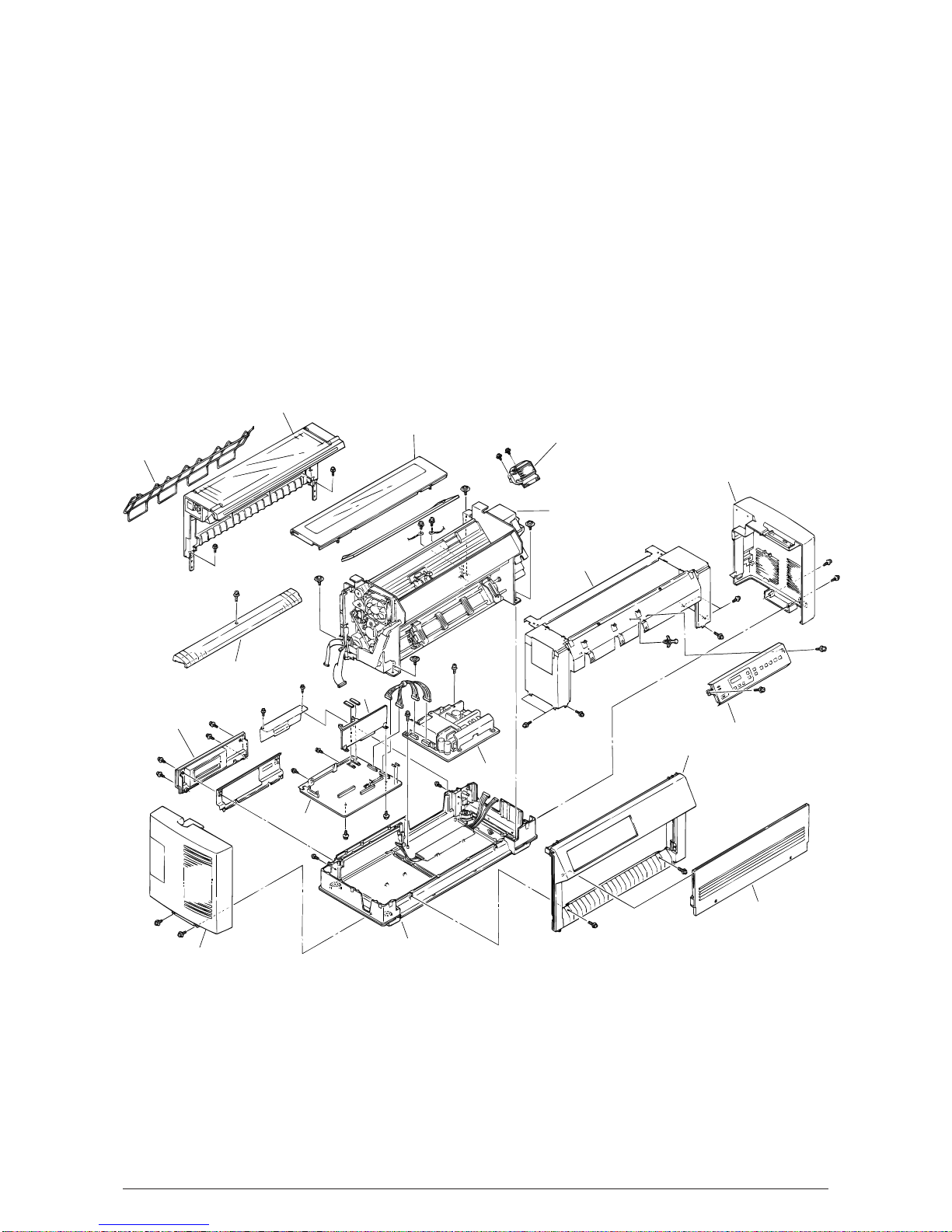
3. PARTS REPLACEMENT........................................................................... 50
3.1 Precautions for Parts Replacement................................................... 50
3.2 Parts Layout....................................................................................... 53
3.3 How to Change Parts......................................................................... 54
3.3.1 Cover-Assy-Access / Cover-Assy-Side (R) / Cover-Assy-Side (L)
/Cover-Assy-Front / Frame-Assy-Rear / Plate-Front (stuck) .................. 55
3.3.2 Printer Unit .............................................................................................. 56
3.3.3 Control Block [Control Board (PMA Printed Board),
Driver Board (PDA Printed Board)] ......................................................... 57
3.3.4 Power Supply Assy ................................................................................. 58
3.3.5 PG Cooling Fan ....................................................................................... 59
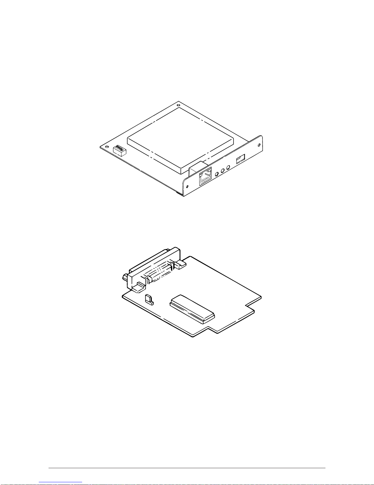
3.3.6 I/F Board (PHA Printed Board) ................................................................60
3.3.7 AG Board (PGA Printed Board) / Connector Cord .................................. 61
3.3.8 AG Motor Assy ........................................................................................ 62
3.3.9 Mini Pitch Belt.......................................................................................... 63
3.3.10 Tractor Change Motor Assy .................................................................... 64
3.3.11 Bail Motor Assy .......................................................................................65
3.3.12 LF Motor Assy .........................................................................................66
3.3.13 Head Cooling Fan 1 ................................................................................67
3.3.14 Head Cooling Fan 2 ................................................................................68
3.3.15 Space Motor ............................................................................................ 69

40496501TH Rev.1 5 /
3.3.16 Operator Board (POA Printed Board)...................................................... 70
3.3.17 Ribbon Feed Assy ................................................................................... 71
3.3.18 Printing Head........................................................................................... 72
3.3.19 Head Cable ............................................................................................. 73
3.3.20 Ribbon Protector ..................................................................................... 74
3.3.21 Space Motor Fan ..................................................................................... 75
3.3.22 Junction Board ........................................................................................ 76
3.3.23 Cover Open Switch Assy / Ribbon Rotation Sensor ............................... 77
3.3.24 Interlock Switch / Interlock Switch Cord Assy ......................................... 78
3.3.25 Knob Bracket Assy .................................................................................. 79
3.3.26 Space Belt ............................................................................................... 80
3.3.27 AG Sensor Frame / Start Searching Sensor ........................................... 81
3.3.28 Paper Jam Sensor Assy / Bail PE Sensor Assy ...................................... 82
3.3.29 Sprocket Assy (L) (R) (Front Tractor) ...................................................... 83
3.3.30 Sheet Feeder Assy (L) Rear / Sheet Feeder Assy (R) Rear ................... 84
3.3.31 Bail Assy.................................................................................................. 87
4. ADJUSTMENTS ........................................................................................ 88
5. CLEANIG AND LUBRICATION ................................................................ 95
5.1 Cleaning............................................................................................. 95
5.2 Lubrication ......................................................................................... 96
6. TROUBLESHOOTING AND REPAIR ....................................................... 104
6.1 Items to Check Before Repair............................................................ 104
6.2 Troubleshooting Table ....................................................................... 104
6.3 Lamp and LCD Display...................................................................... 105
6.4 Part Layout ........................................................................................ 110
6.5 Connection......................................................................................... 113
6.6 Troubleshooting Flow Chart............................................................... 130
7. PARTS LIST .............................................................................................. 161
APPENDIX A PCB LAYOUT.......................................................................... 202
APPENDIX B RS-232C SERIAL INTERFACE BOARD (OPTION) ............... 205
1. GENERAL.......................................................................................... 205
2. OPERATION DESCRIPTION............................................................ 206
2.1 Element Description ................................................................................ 206
2.2 Circuit Description ................................................................................... 206
2.3 Local Test................................................................................................ 209
APPENDIX C MAINTENANCE-SUPPORT FUNCTION ................................ 211
1. Normal mode ..................................................................................... 211
2. Maintenance mode 1 ......................................................................... 212
3. Maintenance mode 2 ......................................................................... 213

40496501TH Rev.1 6
Ribbon
feed
motor
AG
motor
Power supply
FAN
FUSE holder
HEAD
FAN
Motor/Sensor PCB
Power supply unit
Paper width sensor
Print head
Bail PE sensor
Head driver PCB
Main control/
Motor driver PCB
Interface board
(Option)
Interface/Motor
/Sensor PCB
RS232C
I/F
IEEE 1284
I/F
Bail
motor
Tractor
change
motor
LF
motor
Head
FAN
Bail position SW
Tractor change SW
Front PE SW
Rear PE SW
Paper jam sensor
Paper top sensor
AG sensor coil
LCD
Operation panel PCB
AC source
SP
FAN
SP
motor
Cover open SW
Ribbon jam sensor
AG
sensor
PCB
Inter lock SW
1. CONFIGURATION
1.1 Basic System Configuration
The basic system configuration of Pacemark 4410/ Microline 4410 is illustrated in Figure 1.1.
Figure 1.1

40496501TH Rev.1 7
1.2 Printer Specifications
This printer unit is composed with the following hardware.
• Printer mechanism
• Main control/Motor driver board
• Head driver board
• Interface/Motor/Sensor board (including IEEE 1284 bidirectional parallel interface and RS-
232C serial interface)
• Motor/Sensor and AG sensor boards
• Operation panel board
• Power supply unit
• Covers
Figure 1-2 show the printer unit configuration.
Figure 1.2
Sheet guide
Cover Assy Rear
Cover Assy Access Print head
Printer Unit
Cover-Assy-Side(R)
Operation panel Assy
Cover Assy Front
Door Assy Front
Cover Assy Lower
Cover Assy Side(L)
Control Board
Cover Rear B
Guide Paper B
Driver Board
Power Supply Assy
Plate Front
(stuk)

40496501TH Rev.1 8
1.3 Option Specifications
Options available for Pacemark 4410/ Microline 4410 are as follows.
(1) Interface boards
(a) Oki-HSP (MUPIS) Network card
(b) 300/500 Series Serial/ HSP Adapter
• RS232C
• RS422A
• Current Loop

40496501TH Rev.1 9
1.4 Basic Specifications
(1) Dimensions
Width: 768mm(30.24inches) Length: 385mm(15.16inches) Height: 358mm(14.09inches)
(2) Weight
Approx. 42kg (92.6lbs)
(3) Form
Continous Paper
One-part paper
Ream weight: 45 to 90g/m2(12 to 24 lb)
Multiple-part paper Max.0.79mm(0.031inches)total thickness(with front feed)
Max.0.36mm(0.014inches)total thickness(with rear feed)
Paper type Ream weight Number of sheet
Carbon-lined paper Ten sheet maximum including original
35 to 40 g/m2(with front feed)
Pressure-senstive (9 to 11 lbs) Six sheet maximum including original
paper (with rear feed)
Paper
35 to 52 g/m2Seven sheet maximum including original
Interleaf paper (9 to 14 lbs) (with front feed)
Corbon paper Four sheet maximum including original
34 g/m2(9 lbs) (with rear feed)
When 7p or more papers are used for the front tractor, "High Impact Copy" should be
selected in the menu mode to print these papers.
Continuous Envelope
Weight : Max. 90 g/m2(24lb)
Thickness : Max. 0.36mm (0.014 inch)
Width : 76.2 - 254mm (3 - 10 inches)
Media supply :Front paper feed only
Card Weight : Max. 375 g/m2(100lb)
Thickness : Max. 0.20mm (0.008 inch)
Size : 5 x 8 inches (separated)
Media supply :Front paper feed only
Label Thickness : Max 0.28mm (0.011 inch)
Size : Max. 381 x 83mm (15 x 3.25 inches)
Media supply :Front paper feed only
(4) Print speed
Print Mode Character Pitch
10 CPI 12 CPI 15 CPI 17.1 CPI 20 CPI
HSD 1066 CPS 1066 CPS 1066 CPS 1066 CPS 1066 CPS
NLQ 200 CPS 200 CPS 200 CPS 200 CPS 200 CPS
UTILITY 800 CPS 800 CPS 800 CPS 800 CPS 800 CPS

40496501TH Rev.1 10
(5) Maximum Number of Dot Columns per Line
a) Graphics
Single Density Double Density Quadruple Density
816 1,632 3,264
b) Text
Print Mode Character Pitch (CP)
10 CPI 12 CPI 15 CPI 17.1 CPI 20 CPI
ML, EPSON, IBM UTILITY 1,632 1,958 2,448 2,798 3,264
ML, EPSON, IBM NLQ 3,264 3,917 4,896 5,596 6,528
ML, EPSON, IBM HSD 1,224 1,468 1,836 2,098 2,448
(6) Maximun Number of Character per Line
Character Pitch (CPI) 5 6 7.5 8.5 10 12 15 17.1 20
ML EPSON IBM 68 81 102 116 136 163 204 233 272
(7) Printhead
Print method: Impact dot matrix
Number of dot wires: 9 wires x 2 rows
Dot wire diameter: 0.36mm(0.014inch)
(8) Line feed Speed
6 LPI spacing, one LF = 60 ms
8 LPI spacing, one LF = 52 ms
Continuous paper feed rate is 15 inches per second. (at head gap 1, 2)
(9) Line Feed Pitches
6 LPI 0.167 inch (4.23mm)
8 LPI 0.125 inch (3.175mm)
A variable line feed pitch of n/216 inch (integer n: 0 ≤n ≤255) can also be specified. Also,
7/72 inch and n/72 inch can be specified.
PROPRINTER n : 1 ≤n ≤255
EPSON n : 1 ≤n ≤255 (Cannot specify MSB : 1≤n ≤127)
(10) Power Requirements
a) Input power
Single-phase AC
Voltage : 120VAC +5.5%, -15%
230 VAC ±15%
Frequency : 50/60Hz ±2%
b) Power consumption
Local Test : Max. 295 W (Rolling ASCII, Utility)
Idle : Max. 15W (Energy Star compliant)
c) AC power cable
Length : Approximately 5.9 It (1.8 m)
Cable conforms to the UL, CSA, and European Standards.

40496501TH Rev.1 11
(11) Ambient temperature and relative humidity
Operating Non-operating Storage Transportation Unit
Temperature 41 to 95 32 to 109.4 14 to 122 -40 to 158 °F
(5 to 35) (0 to 43) (-10 to 50) (-40 to 70) (°C)
Relative 20 to 80 10 to 90 5 to 95 5 to 95 %RH
Humidity
Avoid condensation at all times.
(12) Vibration
Operating : Max. 0.3G (5 to 150 Hz) (except at resonant frequency)
Non-operating : Max. 1G (5 to 150 Hz) (except at resonant frequency)
(13) Impact (Drop Test)
Packing : 12" Drop
(14) Noise
The 8-second average noise is Max. 55 dBA in quiet utility mode. (ISO 7779)
(15) Ribbon
Genuine OKI cartridge ribbon
Ink color : Black
Ribbon life : Approximately 15 million characters (Characters in Utility mode)
(16) Reliability
a) MTBF (mean time between failures)
12,000 hours of power-on time at 25% duty cycle and 35% page density.
b) Printhead life
400 million characters (average) in 10 CPI Utility print mode at 25% duty cycle and 35%
page density.
c) Printer life
12,000 hours of power-on time at 25% duty cycle and 35% page density, or 5 years.
d) MTTR
30 minutes, major Sub-assembly level.
Definition of terms
• Duty cycle : Actual operation rate
• Page density : The proportion in area of characters and spaces within print head
PPmovable area.
• Power on Time : 8H/day, 25days/month and 12 months/year.

40496501TH Rev.1 12
2. THEORY OF OPERATION
2.1 Electrical Operation
The electrical operation of the printer circuit is described in this section.
2.1.1 Summary
Fig. 2-1 shows the block diagram of the printer.
Thecontrolboardismadeupofthemicroprocessors,peripheralcircuits,drivecircuits,sensorsand
interface connectors.
The power to the control board is supplied by the power board through the connector cord.
Thepwertootherelectricalpartsisalsodistributedthroughtheconnectorswithinthecontrolboard.
2.1.2 Microprocessor and the peripheral circuit
(1) Microprocessor (IC24: 80C186-16)
This processor is a CMOS single-chip computer with integrated peripheral device functions
and a 16 bit MPU core.
The processor has a 20 bit address bus and a 16 bit data bus.
It is capable of accessing up to 4M bit program memory and 4M bit of data memory.
The following characteristics are also provided:
• High-Speed DMA Channel x 2
• Programmable Interrupt Controller
• Programmable 16-bit Timer x 3
• Programmable Memory and Peripheral Chip-Select Logic
• Programmable Wait State Generator
• Local Bus Controller
And others.
The function of this microprocessor is to provide a central mechanism for the entire printer
by executing the control program through the LSI and driver circuits.

40496501TH Rev.1 13
Figure 2.1
to ALM circuit
LF motor
driver
Sub LSI #1
72V017
Sub LSI #2
72V017
AG motor
driver
Sensor, SW
DIP SW
Bail motor
driver
Paper path
switching
motor driver
to ALM circuit
to ALM
circuit
to ALM circuit
to ALM circuit
ALM circuit
Head/ motor driver POWEROFF-P
SP motor
SP motor driver
FL ROM
(8M)
+44V
Power Supply
Unit
CPU
80C186
32
MHz
+12V
Each part
+ 5V
-12V
0V
EP
POWOFF-P
POWDOWN-P
AC DOWN-P
POW ONRST-N
POWALM-P
CG,
ROM
(4M)
PRG,
ROM
(4M)
Slit sensor
IEEE1284
BUF
BUF
BUF
OPpanel
OPpanel
LSI
DRAM
(4M)
RS232
LSI
D/R
EEPROM
LCD
HEAD
Head driver
AG sensor
Ribbon motor
driver
SRAM
(1M)
NHDC LSI
2/2
NHDC LSI
1/2
Main LSI
BUF
MUPIS
card
(x1)
Extended slot
<OPTION>
LAN
ML300's/ 500's
OPTION
RS232C, TWINAX,
COAX, etc
to ALM circuit
to ALM circuit
AG slit sensor
P/S FANP/S FAN DV.
HD FAN DV.1
HD FAN DV.2
SP FAN DV.
FAN ALM
HD FAN 1
HD FAN 2
SP FAN
CB FAN
Continuous
paper cutter
(option)
Either of them
PM
PM
PM
DC
PM
PM
TFA. TFD.720S
ALE/ RD/ WR/ CS/ CLK
AD0~AD15
A16~A19/ BHE

40496501TH Rev.1 14
(2) PG ROM (IC46)
Thisisa256x16bits(4Mbit)EPROMwiththecontrolprogramfortheprinterstored.TheMPU
executes instructions under this program.
TheprogramROMisassignedtotheprogrammemoryareaoftheMPUandisfetchedbythe
RD signal of the MPU.
The following shows the operation of the memory access.
Figure 2.2
MPU CLOCK
ALE
A16~BHE
AD0~AD15
RD
CS
AD0~AD15
A16~BHE
MPU Main LSI PG ROM
NHDC LSI
A16-BHE
A0–A15 D0–D15
ALE
RD
WR
CS
CLK
BANK0
BANKS
CS
A17
A16
A0~A15
OE
CE
A1~A16

40496501TH Rev.1 15
Figure 2.3
(3) DRAM(IC28)
TheRAMisCMOSdynamicRAMwith(256Kx16bit)configuration,andusedasbuffers(such
as receiving buffer, printing buffer, DLL buffer and working buffer).
The following shows the examples of the memory access operation.
MPU CLOCK
ALE
A16~BHE
AD0~AD15
RD
AD0~AD15
WR
CS
AD0~AD15
A16~BHE
DRAMD0~D15
DRAMA0~A9
MPU NHDC LSI DRAM
A16~BHE
A0–A15 D0–D15
A0–A15 D0–D15
ALE
RD
WR
CS
CLK
RAS
CASU
CASL
RD
WR

40496501TH Rev.1 16
Figure 2.4
(4) CG ROM (IC48)
This is a 256K x 16 bits (4M bits) EPROM with the font data for the characters stored.
CGROMisassignedtotheprogrammemoryareaoftheMPUandisfetchedbytheRDsignal
of the MPU.
The following shows the memory access operation.
MPU CLOCK
ALE
A16~BHE
AD0~AD15
RD
CS
AD0~AD15
A16~BHE
MPU Main LSI CG ROM
NHDC LSI
A16-BHE
A0–A15 D0–D15
ALE
RD
WR
CS
CLK
BANK0
BANKS
CS
A17
A16
A0~A15
OE
CE
A1~A16

40496501TH Rev.1 17
(5) EEPROM(IC40)
TheEEPROMisaCMOSserialI/O typememory whichiscapableofelectricallyerasingand
writing 1,024 bits.
The EEPROM contains menu data.
The following shows the memory access operation.
Figure 2.5
NHDC LSI EEPROM
EEPROMWR-P
EEPROMCS-P
EEPROMRD-P
EEPROMCLK-P
DI
CS
DO
SK
,
,
,
,
,
,
,
ReadyBus
twp
D0D15A0A5
11 0
Start
code Operation
code Address Data
tCS
PRE = O
PE
Address
Start
code
Operation
code
EEPROMRD-P
EEPROMWR-P
EEPROMCLK-P
EEPROMCS-P
EEPROMRD-P
EEPROMWR-P
EEPROMCLK-P
EEPROMCS-P
D15 D0 D15 D0 D15
0
A0A5
0
11
tCS
PRE = O
PE = X Read cycle timing (READ)
Write cycle timing (WRITE)

40496501TH Rev.1 18
(6) Main LSI (IC38: MSM91U036)
MSM91U036iscontrol LSIforhead data,DCmotor andmodificationof printdata,which has
the following functions.
(a) Head data control
Itdistributesprint data stored intheDRAM over wire arrangementsofthe print head and
outputs it as dot data in synchronism with print timing. In this time, the distribution
complies with each print mode which is specified by the MPU.
(b) Print timing control
It outputs the signals which control the print timing of ODD and EVEN pins on the print
head.
(c) Space motor speed control function
It controls the space motor with micro-programs to accelerate/decelerate it.
This LSI also controls the speed of the space motor in agreement with each print mode.
(d) I/O port
This printer has 8-bit output port which is used for controlling the SRAM.
(e) Head position count
It counts the outputs from slit sensors (SPPHASE A, B) located on the space motor to
keep monitoring the current position of the print head.
(f) Print data modifying function
It modifies the print data stored in the DRAM with command inputs from the MPU.
(h) DMA control function
It outputs a DMA request to the MPU, simultaneously controlling the DMA.
This LSI is connected in multiplex to the MPU.

40496501TH Rev.1 19
Figure 2.6
MPU CLOCK
ALE
A16~BHE
AD0~AD15
RD
AD0~AD15
WR
CS
AD0~AD15
A16~BHE
MPU Main LSI
A16~BHE
A0–A15 D0–D15
A0–A15 D0–D15
ALE
RD
WR
CS
CLK

40496501TH Rev.1 20
(7) NHDC LSI(IC27: TC190G08CF-7036)
This LSI controls timer, interruption, memories, printing, external interface, motor drive
interface.
(a) Timer control
It controls the watchdog timer for detecting any out-of-control program, baud rate
generator for setting the baud rate of the serial interface, and pulse generation timer for
AG plus count.
(b) Interruption control
It controls LSI inside interruptions, external interruptions and interruptions from an
external interface as outputs for the MPU.
(c) Memory control
DRAMandSRAM control, chip select output controlofROM, flash memory and MUPIS,
and bank switch control for expanding their memory spaces.
(d) Print control
It creates a print timing corresponding to the print DPI to control the possition and print
correction for pins.
ThisalsocontrolstheprintMaskand DMACwhichreadsprintdatafromthe memoryand
transmits it to the print output buffer.
(e) External interface
It controls various interfaces for main LSI, IEEE1284, serial, MUPIS, OpePaneLSI,
EEPROM.
(f) Motor drive interface
Each control of OVDV pulse generation for AG motor, generation of pulse for switching
ribbon motor phase, and OVDV pulse generation for LF motor.
(8) Sub LSI (IC17, IC18: MSM72V017)
This LSI is the I/O port LSI which controls the input/output of various controlling signals with
command inputs from the MPU.
(a) Sub LSI #1 (IC17: MSM72V017)
Input/output control for controlling signals to various sensors, FAN controlling signals,
sensor slice level controlling signals, AG motor controlling signals, and LF motor
controlling signals.
(b) Sub LSI #2 (IC18: MSM72V017)
Input/output control for controlling signals to various sensors, SP motor current control-
lingsignals,externalinterfacecontrollingsignals,TRmotorcontrollingsignals,bailmotor
controlling signals, cutter motor (for optional connection) controlling signals.
(9) Serial I/F LSI (IC35: 85L30)
ThisLSIistheserialI/FLSIwhichcontrolstheinput/outputofserialI/Fcontrollingsignalswith
command inputs from the MPU.
Other manuals for PACEMARK 4410
2
This manual suits for next models
1
Table of contents
Other Oki Printer manuals

Oki
Oki ML420 Series User manual

Oki
Oki B721dn Original instructions

Oki
Oki C9650hn User manual

Oki
Oki GL408e User manual

Oki
Oki B6100n User manual

Oki
Oki C830dn Operation and maintenance manual

Oki
Oki C810n Quick start guide

Oki
Oki C9600hn User manual

Oki
Oki LE810DT Quick start guide

Oki
Oki B4100 User manual

Oki
Oki B2200 Service manual

Oki
Oki C6100dn Original instructions

Oki
Oki C9600hdn Configuration guide

Oki
Oki OKIPAGE14e User manual

Oki
Oki proColor Pro930 Series User manual

Oki
Oki B6250dn Installation instructions

Oki
Oki C9600hdn Use and maintenance manual

Oki
Oki C3200n User manual

Oki
Oki OKIPAGE 14i User manual

Oki
Oki C6050dn User manual