Oki OKIPAGE 8z User manual

Service Manual for OKIPAGE 8z
Chapter 0 Introduction
Page: 1
Front Cover
Service Guide
OKIPAGE 8z
Digital LED Page Printer
Adobe Acrobat printable reference copy
of the OKIDATA Service Training Manual.
07/18/2000
Note: This Adobe Acrobat version of the Okidata Service Training Manual was built with the pictures
rendered at 72 dpi, which is ideal for screen viewing. For future updates to this manual, and
more on-line information visit our Business Partner Exchange (BPX) at
http://bpx.okidata.com.
Copyright 2000, Oki Data, Division of OKI America, Inc. All rights reserved. See the Oki Data Business Partner Exchange
(BPX) for any updates to this material. (http://bpx.okidata.com)

Table of Contents Page
Service Manual for OKIPAGE 8z
0 Introduction
Preface 1
1 Configuration
Configuration 2
....1.1 System Configuration 3
....1.2 Printer Configuration 4
....1.3 Specification 5
....1.4 Safety Standards 6
........1.4.1 Certification Label 7
........1.4.2 Warning Label 8
2 Operation Description
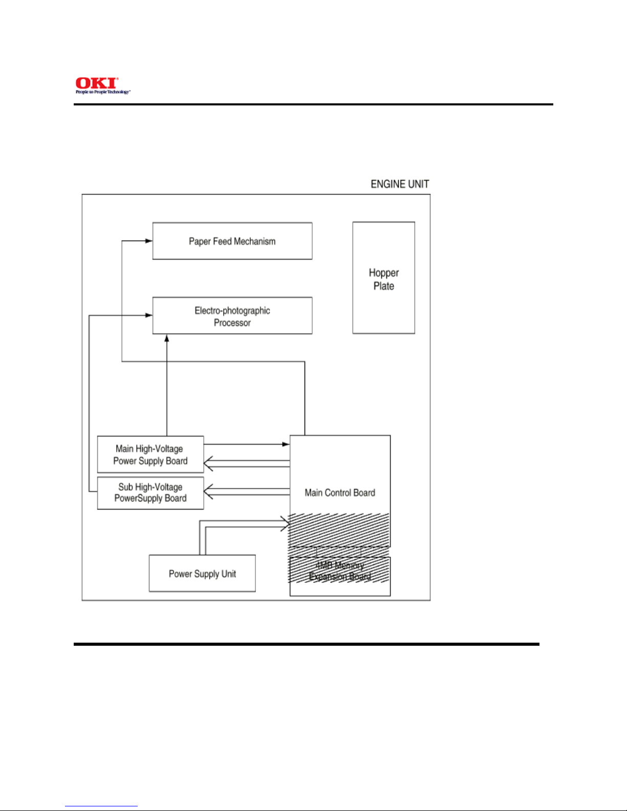
2.0 Operation Description 9
2.1 Main Control Board 10
2.2 Power Supply Unit 11
2.3 High-Voltage Power Supply Board 12
2.4 Electro-Photographic Processor 13
2.5 Electro-Photographic Process 14
....2.5.1 Explanation of Each Process Operation 15
2.6 Paper Jam Detection 16
2.7 Toner Low Detection 17
2.8 Cover Open 18
2.9 Detecting ID existence 19
3 Parts Replacement
Parts Replacements 20
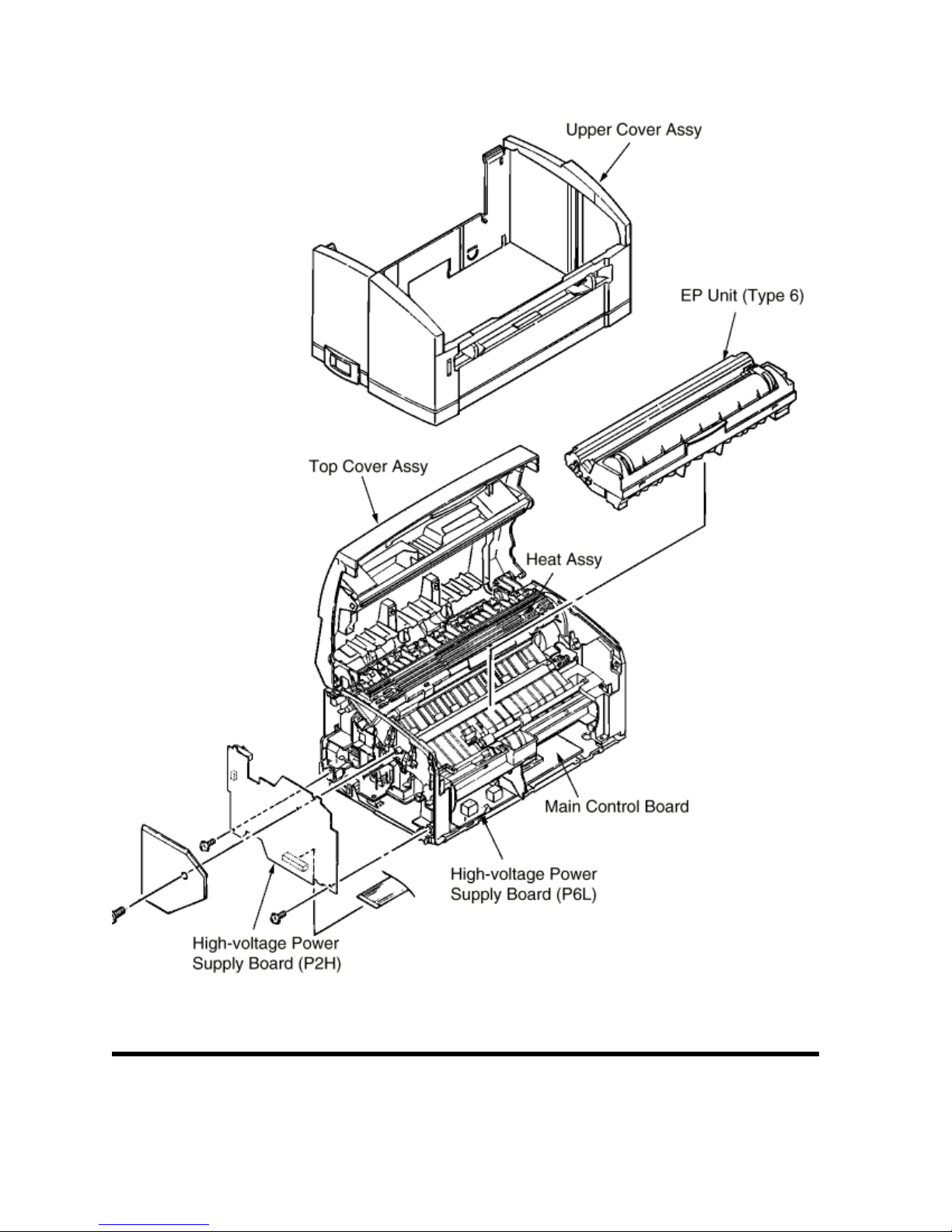
....3.1 Precautions for Parts Replacement 21
....3.2 Parts Layout 22
........Upper Cover Assy 23
........Base Frame Unit 24
........Base Plate Unit 25
....3.3 Replacing Parts 26
........3.3.1 Hopper Plate 27
........3.3.2 LED Head and Head Spring 28
........3.3.3 Transfer Roller 29
........3.3.4 Upper Cover Assy 30
........3.3.5 High-Voltage Power Supply Board (P2H/P6L) 31
........3.3.6 Top Cover Assy and Flat Cable Assy 32
........3.3.7 Paper Holder 33
........3.3.8 Side Plate M and Idle Gear 34
........3.3.9 Heat Assy 35
........3.3.10 Drive Shaft E (Eject) and Eject Roller 36
........3.3.11 Pressure Roller B (Back Up Roller) 37
........3.3.12 Separator Guide 38
........3.3.13 Pulse Motor (Main) 39
........3.3.14 Hopping Shaft Assy 40
........3.3.15 Resist Roller 41
........3.3.16 Paper Sensor E, Paper Sensor Exit and Toner
Sensor Assy 42
........3.3.17 Base Plate 43
4 Adjustment
4.0 Adjustment 44

Table of Contents Page
....4.1 Adjustment Types and Functions 45
........4.1.1 Printer Driver 46
........4.1.2 Engine Maintenance Utility 47
....4.2 Adjustment When Replacing a Part 48
........4.2.1 Setting LED Head Drive Time 49
........4.2.2 Uploading and Downloading EEPROM Data 50
5 Periodical Maintenance
5.1 Periodical Replacement Parts 51
5.2 Cleaning 52
....5.2.1 Cleaning the LED Lens Array 53
6 Troubleshooting Procedures
6.1 Troubleshooting Tips 54
6.2 Check Points Before Correcting Image Problems 55
6.3 Notes When Correcting Image Problems 56
6.4 Preparation Before Troubleshooting 57
6.5 Troubleshooting 58
....6.5.1 Status Monitor Message List 59
....6.5.2 Status Message Troubleshooting 60
....6.5.3 Image Troubleshooting 61
........(1) An image is light or blurred entirely 62
........(2) Dark background density 63
........(3) A blank paper is output 64
........(4) Vertical black belt/stripe 65
........(5) Cyclic defect 66
........(6) A blank paper is output 67
........(7) Poor fusing 68
........(8) Vertical white belt/stripe 69
........Contents - Figure 6-4 70
........Contents - Figure 6-5 71
7 Wiring Diagram
7.1 Interconnect Signal Diagram 72
7.2 PCB Layout 73
....7.2.1 Main Control Board (U8S PCB) 74
....7.2.2 High-Voltage Power Supply Board 75
8 Parts List
Cover Assy Upper 76
Base Frame Unit 77
Heat Assy 78
Base Plate Unit 79
A Local Printing
Local Printing 80
B Parallel Interface
Parallel Interface 81
C Maintenance Utility
Outline of Maintenance Utility 82
Detail of Each Function 83
....4.1 Engine Menu Setting 84
....4.2 Engine Counter 85
....4.3 Printer Status 86
....4.4 Test Print 87
....4.5 Option 88

Table of Contents Page
....4.6 About 89
....4.7 Reload 90
.... 4.8 Exit 91
D Universal Serial Bus (USB)
USB Specifications 92

Service Manual for OKIPAGE 8z
Chapter 0 Introduction
Page: 1
Preface
This Service Handbook describes the field maintenance procedures for the OKIPAGE 8z.
This manual is written for use by service persons. Please note that you should refer to the Printer User's Manual for
operating procedures.
Copyright 2000, Oki Data, Division of OKI America, Inc. All rights reserved. See the Oki Data Business Partner Exchange
(BPX) for any updates to this material. (http://bpx.okidata.com)

Service Manual for OKIPAGE 8z
Chapter 1 Configuration
Page: 2
Configuration
System Configuration
Printer Configuration
Specification
Safety Standards
Copyright 2000, Oki Data, Division of OKI America, Inc. All rights reserved. See the Oki Data Business Partner Exchange
(BPX) for any updates to this material. (http://bpx.okidata.com)

Service Manual for OKIPAGE 8z
Chapter 1 Configuration
Page: 3
1.1 System Configuration
The OKIPAGE 8z consists of a control block, a power supply unit, and an engine block. (See Figure 1-1
below.)
Figure 1-1
Copyright 2000, Oki Data, Division of OKI America, Inc. All rights reserved. See the Oki Data Business Partner Exchange
(BPX) for any updates to this material. (http://bpx.okidata.com)

Service Manual for OKIPAGE 8z
Chapter 1 Configuration
Page: 4
1.2 Printer Configuration
The printer unit consists of the following five hardware components:
Electro-Photographic Processorl
Paper Feederl
Main Control Boardl
High-Voltage Power Supply Boardl
Power Supply Unitl
Figure 1-2 is the configuration of the printer unit.

Figure 1-2
Copyright 2000, Oki Data, Division of OKI America, Inc. All rights reserved. See the Oki Data Business Partner Exchange
(BPX) for any updates to this material. (http://bpx.okidata.com)

Service Manual for OKIPAGE 8z
Chapter 1 Configuration
Page: 5
1.3 Specification
(1) Type: Desktop
(2) Outside dimensions
(excludes protruding
portion)
Height: 5.9" (150 mm)
Width 12.2" (310 mm)
Depth 7.5" (191mm)
(3) Weight 8.4 lbs. (3.8kg)
(4) Development
method
Exposure method
Dry non-magnetic development system
LED stationary head
(5) Paper used <Type>
Standard paperl- Xerox 4200 (20 lbs)
Application paper (manual face-up feed)l- Label
- Envelope
- OHP paper (Transparency)
<Size>
14" (355.6 mm) (Max.) x 8.5" (215.9 mm)
<Thickness>
Automatic feed: 16 to 28 lbs (60 to 105 g/m2)
- Manual feed: Label, Envelope, OHP paper (transparency)
(6) Printing speed: First print: 23 seconds (A4) (after warm-up)
Continuous print: 8 sheets/minute (A4)
Warm-up time: 40 seconds (120 VAC for ODA, 230 VAC for
OEL/INT) (at room temperature 77oF (25oC)
(7) Paper feeding
method Automatic paper feed or manual paper feed
(8) Paper delivery
method Face down
(9) Resolution 600 dpi x 600 dpi (true)
(10) Power input 230 VAC +/-10% (for OEL/INT)
120 VAC +/-15% for (ODA)
(11) Power consumption Peak: Approx. 450W
Typical operation: Approx. 100W
Idle: Approx. 30W
Power save mode: Approx. 5W
(12) Temperature and
humidity
Temperature Humidity

During operation 10 to 32oC 20 to 80% RH (relative humidity)
In storage -10 to +43oC 10 to 90% RH (relative humidity)
No condensation is permissible.
Caution: Temperature and humidity in storage are measured with the OKIPAGE 8z being packed; they
are valid for one year.
(13) Noise During operation: 48 dB (A) or less
Standby: 38 dB (A) or less
(14) Consumables Toner cartridge kit - 1,500 (5% duty) ---- 45g cartridge kit
Image drum cartridge - 10,000 (at continuous printing)
Copyright 2000, Oki Data, Division of OKI America, Inc. All rights reserved. See the Oki Data Business Partner Exchange
(BPX) for any updates to this material. (http://bpx.okidata.com)

Service Manual for OKIPAGE 8z
Chapter 1 Configuration
Page: 6
1.4 Safety Standards
1.4.1 Certification Label
1.4.2 Warning Label
Copyright 2000, Oki Data, Division of OKI America, Inc. All rights reserved. See the Oki Data Business Partner Exchange
(BPX) for any updates to this material. (http://bpx.okidata.com)

Service Manual for OKIPAGE 8z
Chapter 1 Configuration
Page: 7
1.4.1 Certification Label
The safety certification label is affixed to the following location of the OKIPAGE 8z:
Copyright 2000, Oki Data, Division of OKI America, Inc. All rights reserved. See the Oki Data Business Partner Exchange
(BPX) for any updates to this material. (http://bpx.okidata.com)

Service Manual for OKIPAGE 8z
Chapter 1 Configuration
Page: 8
1.4.2 Warning Label
Warning labels are affixed to the locations that may cause bodily injury.
During maintenance, do work with enough care while following instructions on these warning labels.
Copyright 2000, Oki Data, Division of OKI America, Inc. All rights reserved. See the Oki Data Business Partner Exchange
(BPX) for any updates to this material. (http://bpx.okidata.com)

Service Manual for OKIPAGE 8z
Chapter 2 Operation Description
Page: 9
2.0 Operation Description
The OKIPAGE 8z consists of a main control board, a high-voltage power supply board, a power supply
unit, and an electro-photographic processor. The OKIPAGE 8z receives print data from a higher-level
interface and sequentially stores it in memory. The OKIPAGE 8z decodes and edits the received data
while storing print data from the interface in memory. It sequentially transfers the edited data to the LED
head for each dot line. The electro-photographic processor then prints the data on sheets of paper.
The display of the higher-level host is used for device operation and status display.
Figure 2-1 is the block diagram of the OKIPAGE 8z.
Figure 2-1 Block Diagram

Copyright 2000, Oki Data, Division of OKI America, Inc. All rights reserved. See the Oki Data Business Partner Exchange
(BPX) for any updates to this material. (http://bpx.okidata.com)

Service Manual for OKIPAGE 8z
Chapter 2 Operation Description
Page: 10
2.1 Main Control Board
The main control board consists of a one-chip CPU, a program ROM, a DRAM, an EEPROM, a host
interface circuit, and a mechanism driving circuit. The mechanism driving circuit consists of an LED head,
a main motor, and an electromagnetic clutch.
(1) One-chip CPU
The one-chip CPU is a custom CPU (8-bit internal bus, 8-bit external bus, 16-MHz clock) incorporating
mask ROM and CPU peripheral devices. This CPU has the functions listed in the table below.
Built-in Device Function
DRAM controller Controls DRAM.
DMA controller Transfers image data from Parallel I/F to DRAM, from
DRAM to a video output port and between CPU and
DRAM.
Parallel interface controller Controls the parallel interface.
Video output port
LED STB output port Controls LED head.
Timer Generates various control timings for monitoring paper
feeding and a paper size.
I/O Port Inputs and outputs the sensor signals and motor
signals, etc. Also performs I/O for EEPROM.
A/D converter Inputs the feedback signals from a high-voltage
generation circuit and thermistor signal.
(2) Program ROM
Program ROM contains a program for the equipment. EPROM is used as program ROM. When mask
ROM in the one-chip CPU explained in (1) above is valid, the EPROM is not mounted. (For details on
short wiring setting, see Section 7.2.)
(3) DRAM
DRAM is used as resident memory.
(4) EEPROM
EEPROM holds the following data:
Menu datalCounter valuelAdjustment valuel

(5) Parallel interface
The parallel interface receives parallel data from the host; it conforms to the IEEE1284 specification.
Copyright 2000, Oki Data, Division of OKI America, Inc. All rights reserved. See the Oki Data Business Partner Exchange
(BPX) for any updates to this material. (http://bpx.okidata.com)

Service Manual for OKIPAGE 8z
Chapter 2 Operation Description
Page: 11
2.2 Power Supply Unit
The power supply unit supplies +5 V and +26 V to the main control board according to 230 VAC / 120 VAC.
Output voltage Application
+5 V Used to generate a logic circuit and a high voltage.
+26 V Used to drive the motor and electromagnetic clutch.
Copyright 2000, Oki Data, Division of OKI America, Inc. All rights reserved. See the Oki Data Business Partner Exchange
(BPX) for any updates to this material. (http://bpx.okidata.com)

Service Manual for OKIPAGE 8z
Chapter 2 Operation Description
Page: 12
2.3 High-Voltage Power Supply Board
(1) High-Voltage power supply circuit
The high-voltage power supply circuit generates the following voltages required for the electro-photographic
processor from +5 V according to the control sequence from the main control board. When the cover is open, +5 V
supply is automatically interrupted to stop high-voltage output.
Output Voltage Application
CH -1.3 KV Voltage to be applied to charge roller.
DB -265 V/+265 V Voltage to be applied to a developing roller.
SB -520 V/ 0 V Voltage to be applied to a sponge roller.
CB +400 V/-1.3 KV Voltage to be applied to a cleaning roller.
TR +500 V ~ +3.5 KV/-750 V Voltage to be applied to a transfer roller.
Caution: The TR voltage varies with medium and transfer roller impedance.
(2) Sensors
The high-voltage power supply board consists of the high-voltage power supply circuit that supplies power to the
electro-photographic processor system and the photosensor that detects a paper feeding system and toners.
Figure 2-2 shows the sensor layout drawing.
Other manuals for OKIPAGE 8z
4
Table of contents
Other Oki Printer manuals

Oki
Oki ML420 Series Quick start guide

Oki
Oki B6250dn User manual

Oki
Oki MPS6500b Operating and maintenance instructions

Oki
Oki C6000dn Service manual

Oki
Oki OKIPAGE 4M Manual

Oki
Oki T400 User manual

Oki
Oki B4200 User manual

Oki
Oki OKIPAGE 10ex Programming manual

Oki
Oki C9600hdn Configuration guide

Oki
Oki B930 Series User manual