Oliver 4060 User manual

4060 16” Professional Tablesaw
Owner’s Manual
Oliver Machinery M-4060 09/2008
Seattle, WA Copyright 2003
info@oliverma hinery.net www.oliverma hinery.net

Warran y
Oliver makes every effort possible to assure that its equipment meets the highest possible standards of
quality and durability. All produ ts sold by Oliver are warranted to the original ustomer to be free from
defe ts for a period of 2 (two) years on all parts, ex luding ele troni s and motors, whi h are warranted
for 1 year. Oliver’s obligation under this warranty shall be ex lusively limited to repairing or repla ing (at
Oliver’s option) produ ts whi h are determined by Oliver to be defe tive upon delivery F.O.B. (return
freight paid by ustomer) to Oliver, and on inspe tion by Oliver. This warranty does not apply to defe ts
due, dire tly or indire tly, to misuse, abuse, negligen e, a idents, unauthorized repairs, alterations, la k
of maintenan e, a ts of nature, or items that would normally be onsumed or require repla ement due to
normal wear. In no event shall Oliver be liable for death, personal or property injury, or damages arising
from the use of its produ ts.
Warning
Read this manual thoroughly before operating the ma hine. Oliver Ma hinery dis laims any liability for
ma hines that have been altered or abused. Oliver Ma hinery reserves the right to effe t at any time,
without prior noti e, those alterations to parts, fittings, and a essory equipment whi h they may deem
ne essary for any reason whatsoever.
For More Informa ion
Oliver Ma hinery is always adding new Industrial Woodworking produ ts to the line. For omplete, up-to-
date produ t information, he k with your lo al Oliver Ma hinery distributor, or visit
www.oliverma hinery.net
2

WARNING
Read this manual ompletely and observe all warning labels on the ma hine. Oliver Ma hinery has made
every attempt to provide a safe, reliable, easy-to-use pie e of ma hinery. Safety, however, is ultimately
the responsibility of the individual ma hine operator. As with any pie e of ma hinery, the operator must
exer ise aution, patien e, and ommon sense to safely run the ma hine. Before operating this produ t,
be ome familiar with the safety rules in the following se tions.
•Always keep guards in place and in proper opera ing condi ion.
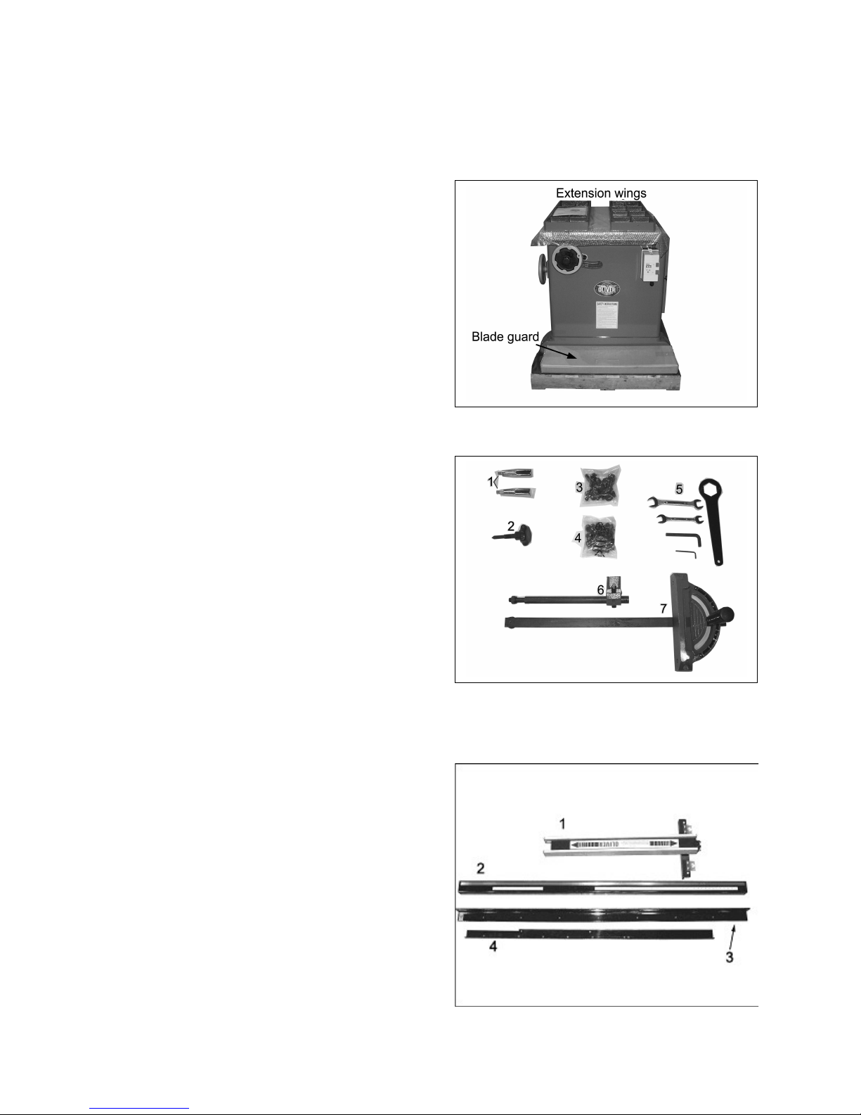
•Use blade guard for every applicable opera ion including all hrough cu s. If guard is removed
for special non- hrough cu s such as dado and rabbe cu s, replace before fur her use of he
saw.
•Keep hands ou of line wi h he saw blade.
•Use a push s ick.
•Do no perform any opera ion freehand.
•Never reach around or over he saw blade.
1. If you are no properly rained in the use of a tablesaw do not use until the proper training has been
obtained.
2. Read, unders and and follow the safety instru tions found in this manual. Know the limitations and
hazards asso iated with this ma hine.
3. Elec rical grounding: Make ertain that the ma hine frame is ele tri ally grounded and that a
ground lead is in luded in the in oming ele tri al servi e. In ases where a ord and plug are used,
make ertain that the grounding plug onne ts to a suitable ground. Follow the grounding pro edure
indi ated in the National Ele tri al Code.
4. Eye safe y: Wear an approved safety shield, goggles, or glasses to prote t eyes. Common
eyeglasses are only impa t-resistant, they are not safety glasses.
5. Personal pro ec ion: Before operating the ma hine, remove tie, rings, wat h and other jewelry and
roll up sleeves above the elbows. Remove all loose outer lothing and onfine long hair. Prote tive
type footwear should be used. Where the noise ex eeds the level of exposure allowed in Se tion
1910.95 of the OSHA Regulations, use hearing prote tive devi es. Do not wear gloves.
6. Guards: Keep the ma hine guards in pla e for every operation for whi h they an be used. If any
guards are removed for maintenan e, DO NOT OPERATE the ma hine until the guards are
reinstalled.
7. Work area: Keep the floor around the ma hine lean and free of s rap material, saw dust, oil and
other liquids to minimize the danger of tripping or slipping. Be sure the table is free of all s rap,
foreign material and tools before starting to use the ma hine. Make ertain the work area is well
lighted and that a proper exhaust system is used to minimize dust. Use anti-skid floor strips on the
floor area where the operator normally stands and mark off ma hine work area. Provide adequate
work spa e around the ma hine.
8. Ma erial condi ion: Do not attempt to saw boards with loose knots or with nails or other foreign
material. Do not attempt to saw twisted, warped, bowed sto k.
9. Opera or posi ion: Maintain a balan ed stan e and keep your body under ontrol at all times.
10. Before s ar ing: Before turning on ma hine, remove all extra equipment su h as keys, wren hes,
s raps, and leaning rags away from the ma hine.
3

11. Careless ac s: Give the work you are doing your undivided attention. Looking around, arrying on a
onversation, and “horseplay” are areless a ts that an result in serious injury.
12. Disconnec all power sources: Before performing any servi e, maintenan e, adjustments or when
hanging blades. A ma hine under repair should be RED TAGGED to show it should not be used
until the maintenan e is omplete.
13. Job comple ion: If the operator leaves the ma hine area for any reason, the tablesaw should be
turned "off" and the blade should ome to a omplete stop before their departure. The key should be
pla ed in the “off” position, removed and given to a supervisor to prevent any unauthorized use of the
tablesaw.
14. Replacemen par s: Use only genuine Oliver Ma hinery fa tory authorized repla ement parts and
a essories; otherwise the warranty and guarantee is null and void.
15. Misuse: Do not use this Oliver tablesaw for other than its intended use. If used for other purposes,
Oliver dis laims any real or implied warranty and holds itself harmless for any injury or damage whi h
may result from that use.
16. Drugs, alcohol and medica ion: Do not operate this ma hine while under the influen e of drugs,
al ohol, or any medi ation.
17. This machine is deigned for utting wood produ ts only. Do not use to ut any kind of metal or
substan e other then wood.
18. Never s ar he saw while a workpie e is in onta t with the blade.
19. Raise or lower he blade only when the ma hine has been turned “off” and the blade has ome to a
omplete stop.
20. Mi er Gauge and Rip Fence: Never use the miter gauge and rip fence at the same time.
21. Damaged Saw Blade: Never use a damaged saw blade or one that has been dropped. Che k the
saw blade for ra ks or missing teeth. Do not use a ra ked or dull blade or one with missing teeth.
Make sure the blade is se urely lo ked on the arbor.
22. Make sure the blade is running in the proper dire tion. Refer to the arrow on the blade. The teeth
should be pointing down when viewing from the front of the saw.
23. Alignmen : Che k the alignment of the splitter to the blade. Also, he k the alignment of the fen e
to the miter slot.
24. Heal h hazards: Some dust reated by power sanding, sawing, grinding, drilling and other
onstru tion a tivities ontains hemi als known to ause an er, birth defe ts or other reprodu tive
harm. Some examples of these hemi als are:
•Lead from lead-based paint.
•Crystalline sili a from bri ks and ement and other masonry produ ts.
•Arseni and hromium from hemi ally-treated lumber.
Your risk from these exposures varies, depending on how often you do this type of work. To redu e
your exposure to these hemi als, work in a well-ventilated area, and work with approved safety
equipment, su h as those dust masks that are spe ifi ally designed to filter out mi ros opi parti les.
Familiarize yourself with the following safety noti es used in this manual:
CAUTION: (This means that if pre autions are not heeded, it may result in minor or moderate injury
and/or possible ma hine damage)
WARNING: (This means that if pre autions are not heeded, it ould result in serious injury or possibly
even death).
4

Table of Con en s Page Number
Warranty......................................................................................................................................................2
Warnings..................................................................................................................................................3-4
Table of Contents........................................................................................................................................5
Spe ifi ations...............................................................................................................................................5
Contents of the Shipping Containers...........................................................................................................6
Ma hine Preparation and Setup..................................................................................................................7
Extension Wing Assembly...........................................................................................................................7
Handwheel Assembly..................................................................................................................................7
Rail Assembly..............................................................................................................................................8
Fen e Assembly and Adjustment................................................................................................................9
Adjusting the S ale Reader.........................................................................................................................9
Adjusting 45° and 90° Stops......................................................................................................................10
Splitter and Blade Guard Assembly...........................................................................................................11
Miter Gauge...............................................................................................................................................12
Controls.....................................................................................................................................................12
Dust Colle tion...........................................................................................................................................12
Ele tri al Conne tions...............................................................................................................................13
Repla ing the Blade...................................................................................................................................13
Maintenan e..............................................................................................................................................14
Troubleshooting....................................................................................................................................15-16
Specifica ions
Model Number.......................................................................................................................................4060
Blade Diameter (In)...................................................................................................................................16”
Arbor Diameter (In)....................................................................................................................................1"
Maximum Depth of Cut at 90 Degrees (In)...........................................................................................5-1/2"
Maximum Depth of Cut at 45 Degrees (In)...........................................................................................4-1/4"
Maximum Cut to the Right of Blade..........................................................................................................52”
Dust Port Diameter (In)................................................................................................................................4
Table Dimensions w/Extensions (LxW).....................................................................................48-1/2” x 38”
Table Height (In)...................................................................................................................................36-½”
Blade Tilt...............................................................................................................................................Right
Arbor Speed RPM.................................................................................................................................3,450
Overall Dimensions (with fen e & rails atta hed)............................................................85”L x 55"W x 42”H
Gross Weight.........................................................................................................................................1040
5

Con en s of he Shipping Con ainers
Oliver 4060, 16” Professional Tablesaw
Saw
On e the top is removed the saw will be as
shown. Inspe t for freight damage and all
the freight arrier if any.
Con en s
Speed handles
2. Angle height lo k
3. Hardware pa ket (wings)
4. Hardware pa ket (rails)
5. Tools
6. Blade guard support bra ket
7. Miter guage
Fence and Rail Assembly
1. Fen e
2. Front rail
3. Front rail support
4. Rear rail
Saw
Contents
Fen e and Rail Assembly
6

Machine Prepara ion and Se up
WARNING!
The equipmen used o lif his machine mus
have a ra ed capaci y a , or above he weigh
of he ablesaw. Failure o comply may
cause serious injury!
The tablesaw must be positioned on a smooth,
level surfa e. The area must be well lit and
have plenty of room to maneuver with large
pie es of wood.
Level the saw front to ba k and side to side
using the supplied leveling bolts. Make sure the
saw is stable before being pla ed into servi e.
Clean all rust prote ted surfa es with a
ommer ial solvent. Do not use a etone,
gasoline, la quer thinner or any type of
flammable solvent, or a leaner that may
damage paint. Cover leaned surfa es with
WD-40 or a 20W ma hine oil.
Pay parti ular attention to leaning in the miter
slot and the fa es of table and extension wing.
Ex ension Wing Assembly
1. Atta h ea h extension wing to table using
the supplied hardware as shown in figure 1.
Snug but do not tighten the bolts.
2. Make sure the mating surfa es are flush at
both the top of the table and the front edge
of the table as shown in figure 2. If the bolts
have not been ompletely tightened, this an
be easily a omplished using a rubber
oated mallet or dead blow.
3. Fully tighten the bolts.
Handwheel Assembly
1. S rew in the speed handle and angle lo k
knob into their respe tive holes as shown in
figure 3. Use the supplied wren h to
se urely tighten the speed handle. Do the
same for both handwheels.
Figure 1
Figure 2
Figure 3
7

Rail Assembly
1. Install the front rail support to the saw using
the four supplied hamfered bolts found in
the hardware pa ket of the rails. It is easiest
to start with the first hole as shown in figure
4, using the floor to rest the end of the rail
on. Note that the rail omes pre-drilled for
use on other saws so it is a matter of lining
up the holes in the saw with the orre t rail
holes.
2. Set the front guide on the support bra ket as
shown in figure 5 and se ure into pla e with
the seven hex bolts also provided in
hardware pa ket. Be areful when pla ing
the rail on the bra ket that it does not fall off
when lining up the holes.
3. Install the rear guide as shown in figure 6
using the supplied hardware.
Figure 4
Figure 5
Figure 6
8

Fence Assembly and Adjus men
1. Pla e the fen e on the rails and he k for
alignment with the mitre guage slot as
shown in Figure 7.
2. If the fen e is not parallel to the mitre guage
slot, lift the fen e off the guides and pla e it
on the table as shown in figure 8. Turn the
appropriate s rew, B to ompensate for the
differen e. Pla e the fen e ba k on the
guides and he k again for alignment to the
mitre guage. If it is still mis-aligned, repeat
the pro edure.
3. If the fen e does not se urely lo k into pla e
with the lo k handle, again adjust s rews (B,
Figure 8) inward equal amounts to put more
pressure on the lo king am to the rail.
4. If the fen e height with respe t to the table
needs to be adjusted use the leveling
s rews (A, Figure 8) in onjun tion with the
leveling knob on the other end of the fen e.
It is best to adjust the height as lose a
possible to the table as long as it doesn’t rub
or bind up on anything as it travels along it’s
rails.
No e: Before leveling he fence, remove he
plas ic screws (A, Figure 8) and apply a hin
coa of oil o he screws before re-ins alling.
Adjus ing he Scale Reader
1. Raise the blade to it’s maximum height.
2. Pla e the fen e
on the guides on the right side of blade and
then slide the fen e toward the blade.
Continue until the fen e just tou hes the
saw teeth. Do not push too hard or the
blade will defle t.
3. Looking at the
right side s ale reader, the red pointer
should mat h up with the zero mark. If not,
loosen the two s rews, B, Figure 9 and slide
the viewer to align the mark with zero.
Tighten the s rews.
4. Move the fen e
to the left side of the blade and repeat the
pro edure for the left side viewer.
Figure 7
Figure 8
Figure 9
9

Adjus ing 45° and 90° S ops
The stops have been adjusted at the fa tory and
should not need any adjustment. If you need to
adjust the stops:
90° S op
1. Disconnec saw from power source.
2. Raise the saw blade to its maximum height
by turning the blade raising handwheel
lo kwise as far as it will go. Pla e a square
on the table and turn the blade tilt
handwheel until the blade omes into 90
degrees with the square. Make sure the
square is between the blade teeth.
3. Loosen the jam nut and turn the s rew until
it hits the stop (A, Figure 11).
4. If ne essary, loosen the s rew (B, Figure
13) and adjust the pointer to zero on the
ba k-up angle s ale.
45° S op
1. Using a 45 guage as shown in figure 12, tilt
the blade until it makes onta t with the
guage making sure the guage does not hit
the saw teeth.
2. Loosen the jam nut and adjust the bolt (A,
Figure 13) until it hits the stop whi h is
similar to the stop in figure 11 but at the
other end of the ra k swing.
3. Adjust the pointer if ne essary.
Figure 11
Figure 12
Figure 13
10

Spli er and Blade Guard Assembly
1. Disconnec saw from power source.
2. Insert the blade guard support rod into hole
A as shown in figure 17.
3. Remove the table insert then se ure the
blade guard support rod with lo k washer (1)
and nut (2) as shown in figure 18.
4. Lower the blade guard onto the front and
rear bra kets using the provided hex bolt
and washer to se ure into pla e as in figure
19.
5. Adjust the rear support bra ket so that the
rear of the blade guard is in line with the
front of the blade guard and the blade itself.
Figure 17
Figure 18
Figure 19
11

Mi er Gauge
1. The miter guage omes pre-assembled.
Unpa k the miter guage and lean
thoroughly.
2. Be ertain the miter guage ‘T’ slots in the
table are also thoroughly leaned.
3. The miter guage is guided through the ‘T’
slot with a roller guide at the front of the
guide bar. To insert miter guage, first insert
roller guide into ‘T’ slot at front of table.
No e: Always make test uts. The s ale is for
referen e. There are two holes in the miter
gauge fen e used to atta h a wooden fen e.
Con rols (see Figures 24 & 25)
1. Magne ic Swi ch: Stops and starts the
ma hine. This swit h also provides overload
prote tion for the saw motor (Figure 24).
2. Handwheel Lock: There is a handwheel
lo k on both handwheels (B & D of Figure
25). Loosen lo k to turn handwheel and
tighten when blade is in desired lo ation.
3. Blade Heigh Adjus men : Loosen
handwheel lo k. Turn handwheel ‘C’
lo kwise to raise the blade. The blade
should be 1/8”-1/4” above the top of
workpie e, or 3-5 blade teeth above the top
of workpie e.
4. Blade Til Adjus s men : Loosen
handwheel lo k. Turn handle ‘B’ to tilt
blade.
Dus Collec ion
There is a 4” dust port lo ated on the side of saw
abinet. Make sure dust olle tion system has
suffi ient apa ity and su tion for your tablesaw.
Always turn on dust olle tion system before
starting the tablesaw.
Figure 23
Figure 24
Figure 25
12

Elec rical Connec ions
WARNING!
Elec rical connec ions and wiring mus be
done by a qualified elec rician. The machine
mus be properly grounded. Failure o
comply may cause serious injury!
This saw is available in both 1-Phase and 3-
Phase versions.
Elec rical Connec ions for a 3-Phase Uni
This saw is 3-Phase, 220V/440V pre-wired
220V. If you need to swit h the tablesaw from
220V to 440V have a qualified ele tri ian make
the hanges. Oliver Ma hinery re ommends
using a dedi ated ir uit.
Make sure the voltage of your power supply
mat hes the spe ifi ations on the motor plate of
the ma hine.
No e: On ini ial s ar up, urn he saw on wi h
ou he saw blade ins alled in order o
confirm he correc ro a ion. If he saw blade
is on and urning in he wrong direc ion, he
arbor nu could loosen, causing he arbor o
sus ain damage.
The arbor should spin toward the user when
standing in front of the saw. If it does not,
dis onne t the power sour e and reverse any
two power leads, L1, L2, or L3.
Replacing he Blade
1. Disconnec saw from power source.
2. Remove the blade guard.
3. Remove the table insert and raise the blade
ompletely.
4. Use a pie e of wood as a wedge to hold the
blade in pla e while loosening the arbor nut
with the supplied wren h as shown in figure
26. Remove the nut, flange and blade.
No e: Make sure he blade and arbor are
clean before ins alling a new blade. The
blade ee h should poin down when viewing
from he fron of saw. The arbor nu is
reverse hread as shown in figure 26.
Figure 26
Figure 26
13

Main enance
WARNING!
Disconnec he machine from power source
before proceeding wi h any main enance, or
roubleshoo ing! Failure o comply may
cause serious injury!
Periodi ally lean the inside of the ma hine for
dust ontrol. Use an air hose to blow out dust
from motor fan and motor over.
As needed, use a wire brush to lean trunions
and worm gears. Apply a medium vis osity
grease white lithium grease or powdered
graphite to lubri ate worm gears, and trunions.
Periodi ally lubri ate all internal bearing or wear
surfa es with a medium vis osity ma hine oil.
Be sure to lubri ate trunion ways and all
bushings. O asionally oil all other bearing
points, in luding blade guard assembly, miter
guage, and rip fen e.
Keep pulleys and belts free from dirt, dust, oil
and grease.
Repla e worn v-belts as needed.
Remove rust from the tabletop with a
lubri antWD-40 and a S ot h-Brite™ Hand Pad.
Keep a light oat of lubri ant on the table top
when not in use.
Note: Instead of oil, a good quality paste wax
an be applied to the rip fen e and table surfa e.
Paste wax will enhan e the movement of work
pie es a ross the surfa e to whi h it is applied.
In addition to being a lubri ant, paste wax will
help prevent surfa es from rusting.
All bearings on the arbor are shielded and
permanently lubri ated at the fa tory.
Repla e belts and worn parts when needed. If
power ords are worn, ut or damaged din any
way, have them repla ed immediately.
Make sure the teeth of the antiki kba k pawls
are always sharp. Sharpen the dull teeth using
a few light strokes of a fine- ut file.
14

.
Troubleshoo ing
Descrip ion of Symp oms Possible Cause Correc ive Ac ion
Ma hine will not start
1. Fuse blown or ir uit breaker
tripped
2. Cord Damaged
3. Faulty swit h
4. Not onne ted to power
sour e
5. Conne ted to wrong voltage
6. Key in the “OFF” position
7. Emergen y stop button
pressed
1. Repla e fuse or reset ir uit
breaker
2. Have ord repla ed
3. Repla e swit h
4. Che k onne tion
5. Che k voltage
6. Insert key and turn to “ON”
position
7. Rotate emergen y stop button
lo kwise until it pops out
Blade does not ome up to speed
1. Cable too light or too long
2. Low urrent
3. Motor not wired for orre t
voltage
1. Repla e with adequate size
able
2. Conta t lo al ele tri
ompany
3. Refer to motor nameplate for
orre t voltage
Does not make a urate 45° or
90° uts
1. Stops not adjusted orre tly
2. Angle pointer not set
a urately
3. Miter gauge out of adjustment
1. Che k blade with ombination
square and adjust stops
2. Che k blade with ombination
square and adjust pointer
3. Adjust miter gauge
Saw makes unsatisfa tory uts
1. Dull blade
2. Blade mounted ba kwards
3. Gum or pit h on blade
4. In orre t blade for ut
1. Sharpen or repla e blade
2. Turn blade around
3. Remove blade and lean
4. Change blade to orre t type
Material binds blade when ripping
1. Fen e not aligned with blade
2. Warped wood
3. Ex essive feed rate
4. Splitter not aligned with blade
1. Che k and adjust fen e
2. Sele t another pie e of wood
3. Redu e feed rate
4. Align splitter with blade
15

Saw vibrates ex essively
1. Stand on uneven floor
2. Damaged saw blade
3. Bad V-belts
4. Bent pulley
5. Improper motor mounting
6. Loose hardware
1. Reposition on flat, level
surfa e
2. Repla e saw blade
3. Repla e V-belts
4. Repla e pulley
5. Che k and adjust motor
6. Tighten hardware
Material ki ked ba k from blade
1. Rip fen e out of alignment
2. Splitter not aligned with blade
3. Feeding sto k without rip
fen e
4. Splitter not in pla e
5. Dull blade
6. Letting go of material before it
is past blade
7. Anti-ki k ba k paws dull
1. Align rip fen e with miter slot
2. Align splitter with blade
3. Install and use rip fen e
4. Install and use splitter (with
guard)
5. Repla e blade
6. Push material all the way past
blade before releasing work
7. Repla e or sharpen anti-ki k
ba k paws
Blade does not raise or tilt freely Sawdust and debris in raising
and tilting me hanisms Clean and regrease
16


Table of contents
Other Oliver Saw manuals
Popular Saw manuals by other brands

Grizzly
Grizzly EXTREME G0605X owner's manual

Tomahawk
Tomahawk TFS6H instruction manual

Chicago Electric
Chicago Electric 56708 Owner's manual & safety instructions

Axminster
Axminster Excalibur EX-16 user manual

Meister
Meister MMS 710 E Translation of the original instructions

Energer
Energer ENB542BDS instructions