Table of Contents Page Number
Warranty........................................................................................................................................................ 2
Warnings ....................................................................................................................................................3-4
Table of Contents.......................................................................................................................................... 5
Specifications ................................................................................................................................................ 5
Contents of the Shipping Containers ............................................................................................................ 6
Uncrating the Machine .................................................................................................................................. 6
Machine Preparation and Setup ................................................................................................................... 6
Dust Collection .............................................................................................................................................. 7
Electrical Connections................................................................................................................................... 7
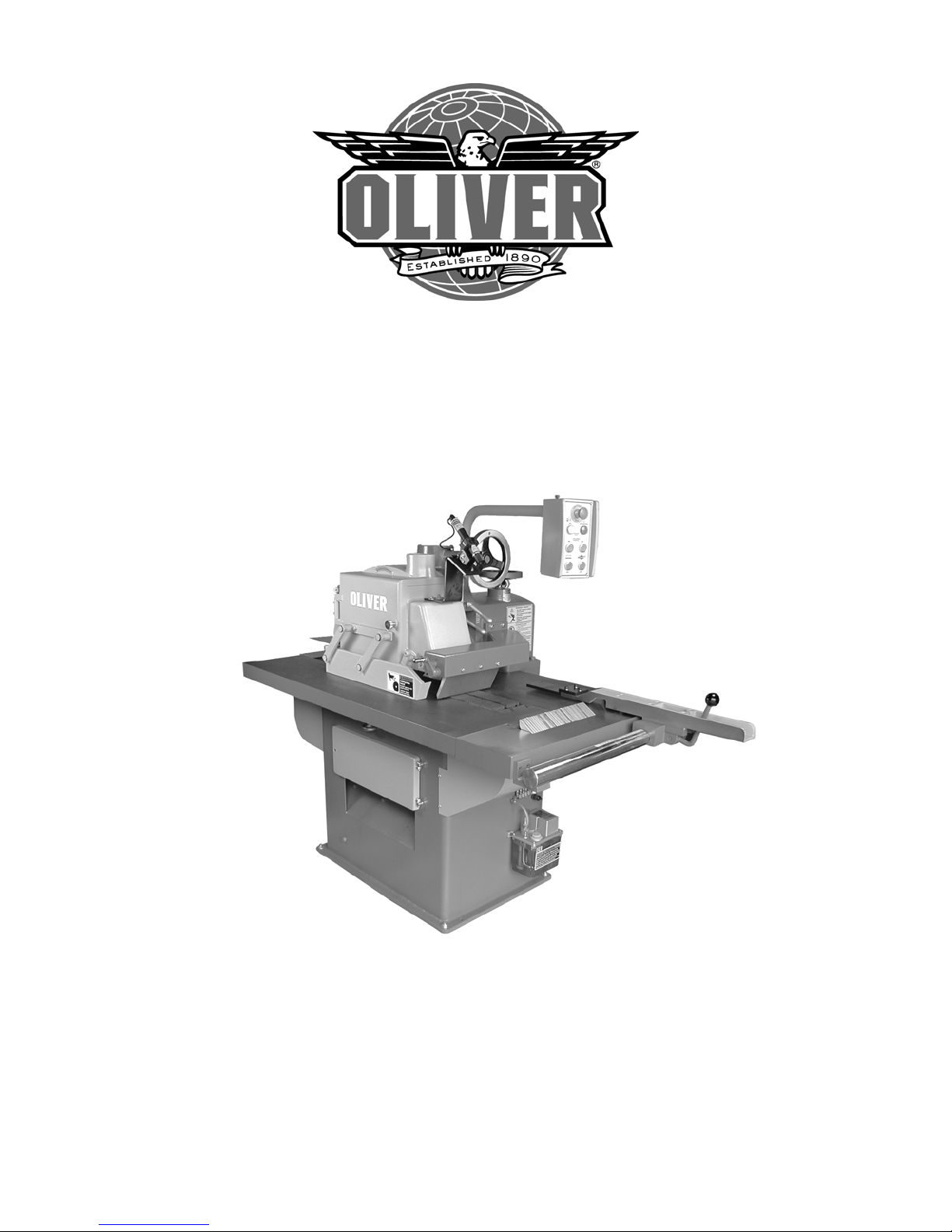
Fence............................................................................................................................................................ 8
Assembly....................................................................................................................................................... 8
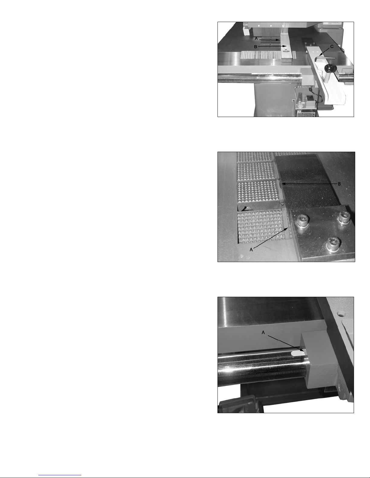
Adjustment of Fence to Blade....................................................................................................................... 8
Adjustment of Rail to blade ........................................................................................................................... 8
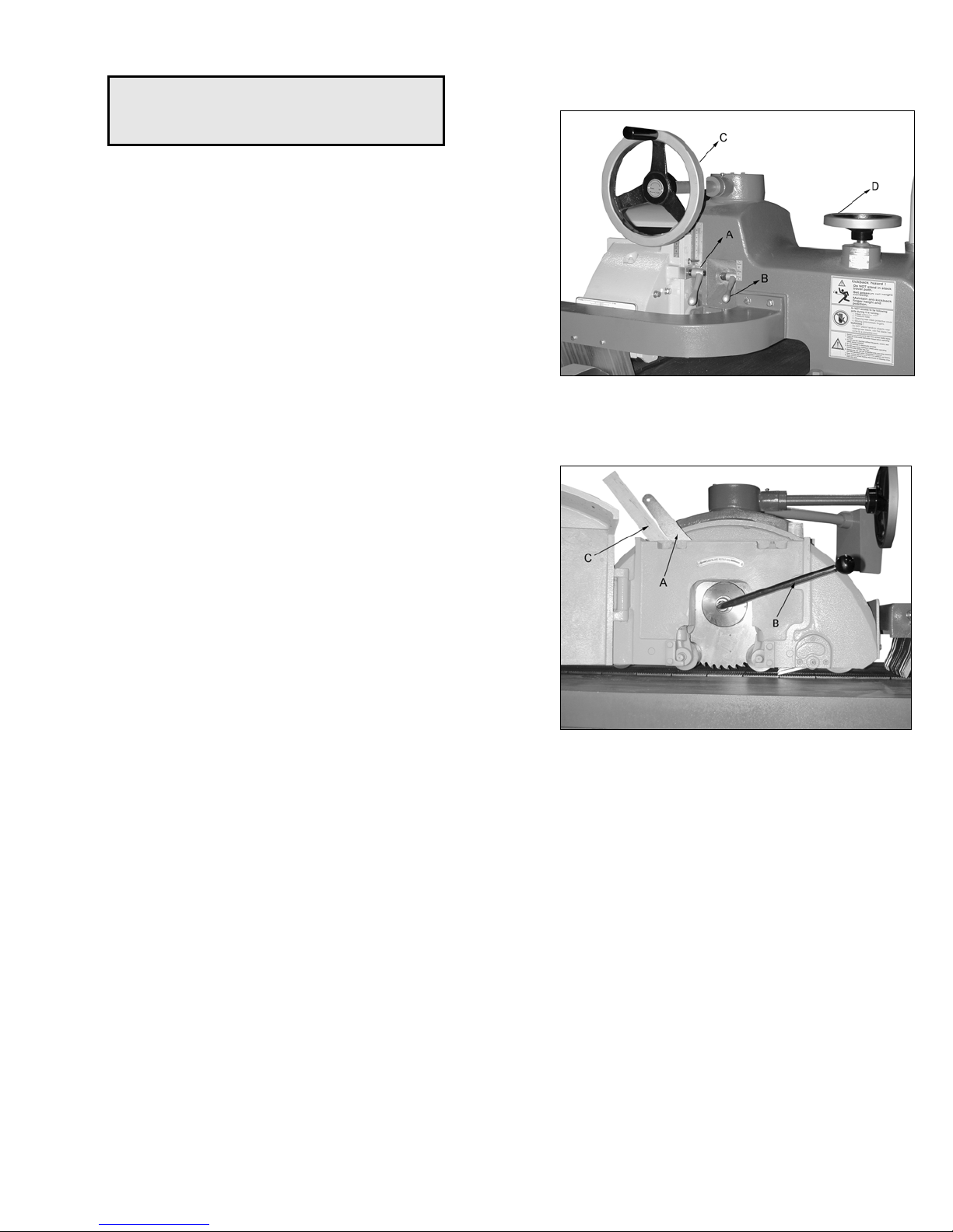
Saw Blade .................................................................................................................................................... 9
Choosing the Correct Saw Blade .................................................................................................................. 9
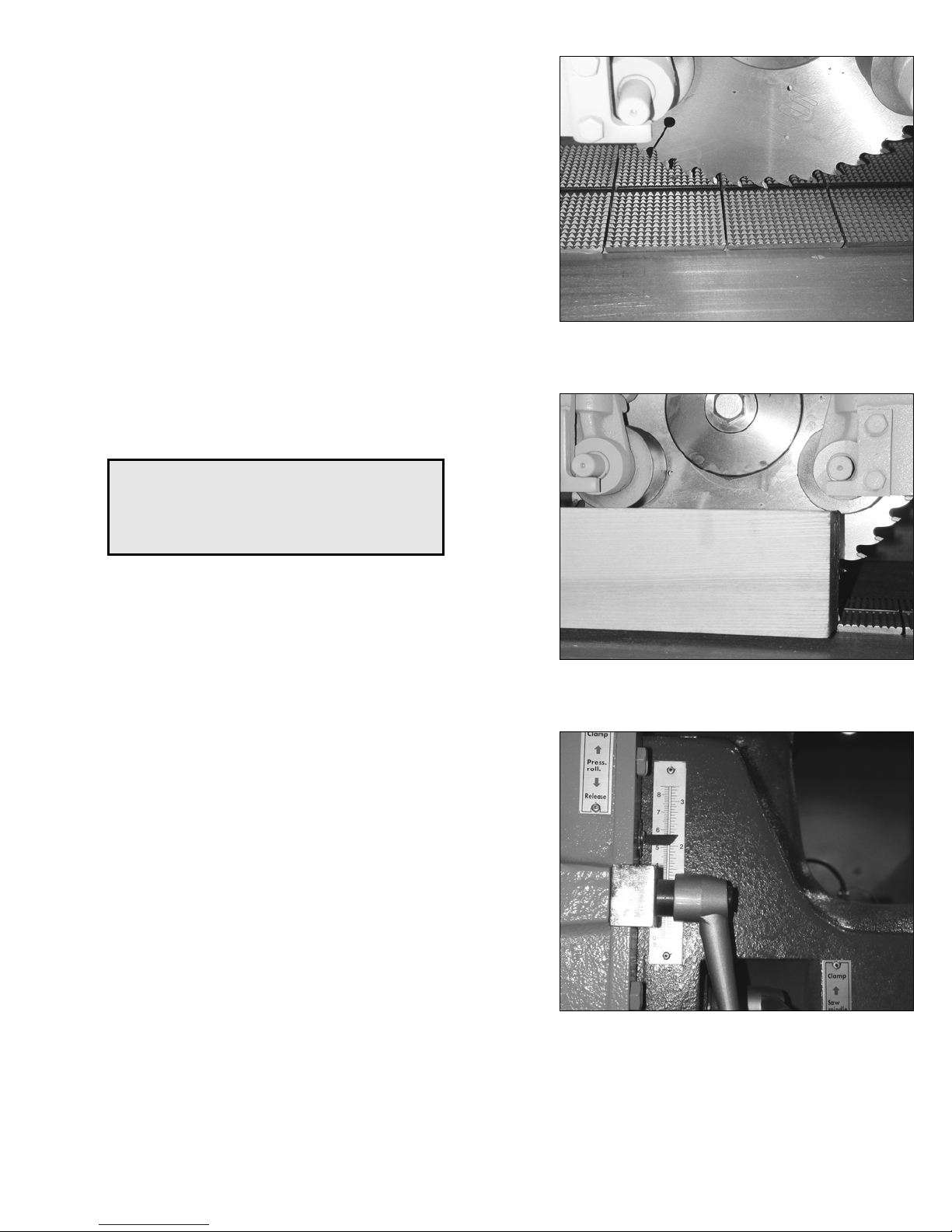
Replacing the Blade ...................................................................................................................................... 9
Setting the Saw Blade Height ..................................................................................................................... 10
Pressure Roller/Carriage.......................................................................................................................... 10
With Respect to Work Piece ....................................................................................................................... 10
Height Adjustment....................................................................................................................................... 10
Chain Oiler ................................................................................................................................................. 11
Adjusting the Interval/Duration.................................................................................................................... 11
Recommended Oil ...................................................................................................................................... 11
Operation ................................................................................................................................................... 12
Proper position of operator.......................................................................................................................... 12
Pre-start....................................................................................................................................................... 12
Start............................................................................................................................................................. 12
Feed Rate.................................................................................................................................................... 13
Maintenance .............................................................................................................................................. 13
Lubrication................................................................................................................................................... 13
Other ........................................................................................................................................................... 13
Troubleshooting .......................................................................................................................................... 14
Specifications
Model No................................................................................................................................................. 4910
Stock No........................................................................................................................................... 4910.001
Arbor Diameter (in.)....................................................................................................................................... 1
Blade Diameter (in.) .................................................................................................................................... 12
Blade Speed (RPM) ............................................................................................................................... 4,500
Feed Speed 3 Speed: .............................................................................................................. 45,60,70 FPM
Cutting Depth (in.) ...................................................................................................................................3-3/8
Maximum Ripping Width (in.)................................................................................................................. 13.75
Minimum Board Length (in.)........................................................................................................................ 14
Pressure Rollers............................................................................................................................................ 6
Anti-Kickback Device(s) ................................................................................................................................ 3
Table Size (W x L/in.).......................................................................................................................... 30 x 50
Table Height (in.)......................................................................................................................................... 30
Dust Collection Port (in.) ............................................................................................................................... 4
Feed Motor..................................................................................................................... 1HP, 3Ph, 220/440V
Controls..................................................................................................................................... 24V Magnetic
Motor ........................................................................................................................... 7.5HP, 3Ph, 220/440V
Shipping Dimension (L x W x H/in.) ............................................................................................ 45 x 59 x 58
Gross Weight (lbs.) ................................................................................................................................. 2310
CFM............................................................................................................ 400CFM at 4500FPM air velocity
5