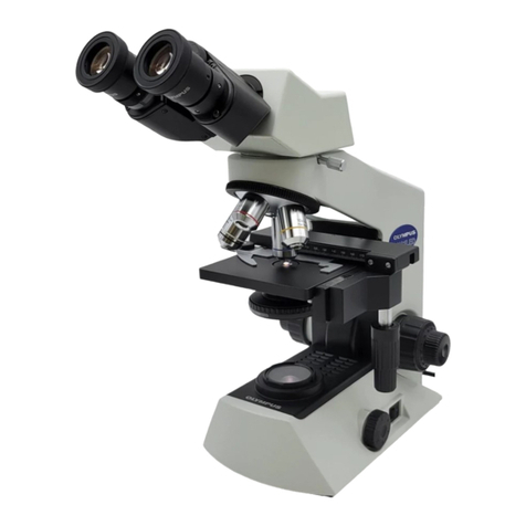
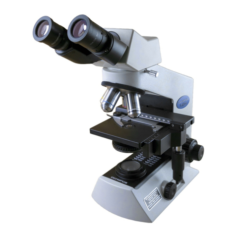
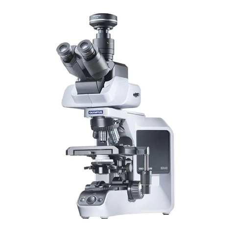
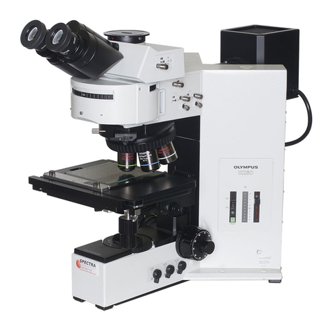
Olympus CH2 Series Operating instructions

OLYMPUS BIOLOGICAL MlCROSCOPE
SERIES
CH2
REPAIR MANUAL
OLYMPUS

CONTENTS
1. OUTLINE OF THE PRODUCT ............................................. 1
2. DISASSEMBLING PROCEDURE ................................. , .......... 7
3. REASSEMBLING AND ADJUSTMENT ...................................... .21

1. OUTLINE OF THE PRODUCT
CONTENTS
1. IOutlineoftheproduct .................................................... 3
2. Specifications ........................................................... 3
-l-

1. Outline of the product
Name of product: OLYMPUS Biological microscope for education and laboratory use.
Model name for internal use: CH2 Series
CHS-F
(With built-in Halogen lamp, 6V 20W)
CHT-F
(With built-in Tungsten lamp, IOOV 30W)
CHD-F
(Mirror or attachable substage illuminator LSK can be mounted.)
2. Specifications
Common items with models CHS-F, CHT-F and CHD-F
(1) Body tube mounting:
(2) Nosepiece:
(3) Stage:
(4) Focusing:
(5) Condenser carrier:
Circular dovetail/groove system.
Analyzer can be accomodated at inside of the dovetail groove.
Quadruple
Fixed plane stage
Attachable mechanical stage can be mounted.
Common axle for coarse and fine focus adjustments.
Stroke: 25 mm (Coarse and fine adjustments)
Fine focus adjustment gradation: 2.5 pm/division
Tension adjustment for coarse focus knobs
Stopper for coarse focus adjustment
Rack and pinion hight displacement
Sleeve type condenser mount, precentered
Common items with models CHS-F and CHT-F
(1) Filter:
(2) Field diaphragm:
(3) Dimensions:
Cobalt filter (32.5C-2), mounted on a standard filter carrier and then
inserted in the condenser carrier.
45 mm dia filter can be used on the light exit window in the base.
Field diaphragm is available for mounting on the light exit window.
Auxiliary lens is located below the condenser carrier.
180 mm (W) x 223 mm (D) x 281 mm (H)”
* 389 mm (H) with binocular tube
(4) Maximum power consumption: 32VA 1OOV/l 1OV
32VA 2OOVf24OV
-3-

CHSF
(1) Light source:
(2) Weight:
6V 20W Halogen lamp
In-base transformer
Light adjustment with resistor coil.
Fuse holder
Detachable main cord
6.2 kg
CHT-F
(1) Light source: 1OOV 30W Tungsten lamp
Light adjustment with resistor coil
Fuse holder
(2) Weight: Detachable main cord
5.8 kg
CHD-F
(1) Mirror: 50 mm dia mirror is available
Plug-in type mount
(2) Illuminator:
Mounting hole: 5 mm ,i.03 mm
Attachable substage illuminator (LSK) is available
Plung-in type mount
(3) Dimensions:
(4) Weight:
Mounting hole: 5 mm +to3 mm
180 mm (W) x 223 mm (D) x 262 mm (H)”
* 370 mm (H) with binocular tube
4.9 kg
CH2-CD (Two lens condenser for CH2)
(1) Mounting onto the microscope: Condenser is inserted into substage sleeve and clamped.
(2) Numerical aperture: NAI .25 (immersed)
(3) Iris diaphragm: Iris opening from 1.7 mm - 29 mm, variable
(4) Type of illumination: Bright field illumination.
Dark field illumination is available if an optional dark field stop is
used.
(5) Filter:
(6) Special accessories:
Phase contrast illumination is also available with optional ring slits.
Cobalt filter is available with a filter holder or auxiliary lens.
(Snap-in type)
1. Filter holder
2. Auxiliary lens
3. Ring slit
CH-2FH (Filter holder for CH2)
(1) Mounting onto the condenser: Filter holder is mounted on the condenser with snap-in type spring
design.
(2) Filter size: 32,5 mm dia cobalt filter
(3) Accessory: Dark field stop
-4-

CH-2FS (Field iris diaphragm for CH2)
(1) Mounting onto the base: Field iris diaphragm is mounted on the light exit of the base
with snap-in type groove and spring.
Auxiliary lens is mounted on the condenser with snap-in type
groove and spring.
(2) Centering of field iris diaphragm: With two centering knobs on the auxiliary lens.
(3) Objectives which the field iris diaphragm which can be focused:
10X - 40X (At 40X the field number can be reduced to 15.)
Iris opening: 1.7 mm dia - 32 mm dia.
(4) Available filter: Auxiliary filter accepts cobalt filter of 32.5 mm dia.
(5) Available accessory: Dark field stop is available to fit on the auxiliary lens.
CH2-DS (Dark field stop for CH2)
(1) Mounting onto the condenser: Drop into auxiliary lens CH2-AL or filter holder CH2-FH and
snap into condenser.
(2) Objectives which can be used for dark field illumination:
4X - 40X. (NA 0.65 max)
(3) Numerical aperture of condenser with CHZ-DS attached:
0.7510.95
CH2-RSlO (10X Ring slit for CH2)
CH2-RS40 (40X Ring slit for CH2)
(1) Mounting on the condenser:
(2) Centering of the ring slit:
(3) Objectives:
Snap-in type
Two centering knobs,
PCDA 10X
PCDA 40X
CH’L-PCD (Universal condenser for CH2)
(1) Mounting on the substage:
(2) Numerical aperture:
(3) Turret:
(4) Centering of ring slit:
(5) Objectives:
(6) Filter:
Insert into condenser sleeve and clamp with clamping knob.
NA1.25 (immersed, brightfield)
4 hole turret.
Bright field , . , With aperture iris diaphragm (iris dia: 1.7 mm
- 29 mm)
Dark field . . . . Dark field illumination for objectives of 10X
- 40x.
1OX ring slit
40X ring slit
Centering with two removable centering keys.
Long barrel objectives (DAch and EDAch)
Phase contrast objectives (PCDAch 1OX and PCDAch 40X)
Green filter and cobalt filter are provided. To be placed on the
light exit on the base.
-5-
2. DISASSEMBLING PROCEDURE
CONTENTS
1. Disassembly of bottom plate of base ......................................... 9
2. Disassembly of light exit unit ............................................... 9
3. Disassembly of condenser carrier, stage and focusing unit ........................ .lO
4. Disassembly of focusing knobs ............................................. .I4
5. Disassembly of rack and pinion ............................................ .I 7
-7-

1. Disassembly of bottom plate of base
l-l.
1-2.
l-3.
2. Disassembly of light exit unit
Place the microscope upside down
move 4 screws (AB4 x 12SA).
Remove screw (AB4 x 12SA) which
the ground wire.
Pull up the bottom plate and remove
the main frame.
and re-
clamps
it from
2-l. Remove 3 screws (CUK2.6 x 10SA) which are
clamping the light exit unit.
-9-

3. Disassembly of condenser carrier, stage and
focusing unit
.. 3-l. Remove the arm (C2-AS) from the base
(C2-BS) by removing 4 screws (AB6 x 16SA).
*Mark the installing position before removal.
3-2. Remove the left outer guide (AB468900) of
the condenser carrier (C2-CH) by removing
screw (CUKSK3 x 1OSA).
3-3. Remove the condenser carrier (AB468800).
-lO-

Remove condenser rack (AA870700) by un-
screwing 2 screws (CUK3 x 6SA).
3-5. Remove the sleeve (AB469000).
*Disassemble the sleeve only when it has a
problem such as poor centration of the con-
denser or it is damaged.
3-5-l. Remove condenser clamping screw (AA-
008000).
3-5-2. Loosen 3 screws (ANU3 x 6SA).
3-5-3. Remove sleeve (AB469000).
3-6. Remove substage knob assembly (A8431 700).
-ll-

3-7. Remove back cover (A8466300) from the
Arm (C2-AS).
3-7-l. Pull out 6 plastic rivets (A8435500).
*Rivets are set as indicated in the following
sketch and will be easily released by pull-
ing on their heads.
3-8.
3-9.
Remove the rack for coarse focus adjustment
(A8469300) by removing 2 screw (A83 x
IOSA) from the back of the arm.
Remove 4 screws (A83 x 10SA) from under-
neath the condenser carrier (A8468800) and
release the guide (A8468600) and the block
(A8009700).
-
12
-

3-11.
3-l 2.
Remove the condenser
the arm (C2-AS).
Note: Do not loose the
denser carrier.
carrier (C2-CH) from
balls (84) of the con-
Release the leaf spring (AB469500)
removing 2 screws (CUK3 x 6SA).
by
Release the stage (AA871800) by removing
4 screws (A84 x 1OSA).
*Disassemble the stage only when you have
a problem such as a damaged stage or poor
alignment to the optical axis.
-13-

4. Disassembly of focusing knobs
Remove the left and right
060700).
*Jimmy the plate at the
easily come off.
cover plates (ABB-
cutout and it will
4-2. Remove the screws (A83 x 8SA) which are
holding the left and right knobs for the fine
focus adjustment (A8059300/A8467500).
“Insert wrenches into the hexagonal holes of
the knobs and rotate them counterclock-
wise.
4-3. Pull out the fine focus knobs.
-14
-

4-4. Remove washer (AA7784400).
4-5. Remove the spring washer.
*Either A8021 700 or A8022600,
is the most suitable, is used there. whichever
4-6. Remove nut (AB466500).
*The threaded part is coated with adhesive, so
dip it in a mixed solution, and remove it
using an eye wrench (KKA84665).
-15-

4.-7.
4-8. Remove spring (AA784200).
Remove the left coarse focus knob (AB-
467300).
*Hold the right coarse handle with your hand,
and pull it out in the arrow direction.
4-9. Pull out the right coarse
direction of the arrow. focus knob in the
-16-

4-10. Remove plate (AA7830001 by removing 3
screws (CSTB3 xlOSA).
4-l 1. Remove the gears.
[r AA783300
AA783400
c AA783400
A8467000
C
AA787800
AA787900
5. Diisassembly of rack
and
pinion
5-l. Place tools KG2010 and KKAA7828 on the
right gear (AA782700) and the left nut
(AA782800) respectively, then rotate them
counter-clockwise and remove the nut.
*The nut is fixed with glue.
*Balls B1/16 are held in the bearing, be care-
full not to lose them.
-17-

5-2.
5-3.
5-4. Remove washer (AA783700).
Pull out pinion asssembly (pinion AB466700
and gear AA782700) in the direction of the
arrow and remove balls B1/16.
Remove the pinion bearing. Remove 2 scr
(ACU3 x 6SA) and pull the bearing in
direction of the arrow.
‘ews
the
-18-

5-5. Remove spring (AA783800).
5-6.
5-7. Remove stopper (AA001 500).
Remove knob (AB467100) by
clockwise (direction of the arrow) rotating it
- 19 -

5-8.
5-9. Remove the clutch plate.
Remove knob (AA941600)
counterclockwise. rotating it
-2o-

3. REASSEMBLY AND ADJUSTMENT
CONTENTS
1. Assembling the pinion assembly ............................................. 23
2. Assembling the upper stopper of coarse focus adjustment ......................... 26
3. Assembling the coarse and fine focus adjustment unit ............................ 27
4. Assembling the condenser carrier, stage and focusing unit ......................... 32
5. Assembling the light exit unit. .............................................. 38
6. Assembling the bottom plate of the base ...................................... 38
7. Perpendicularity adjustment of stage ......................................... 39
8. Sensitivity adjustment of fine focus movement ................................. 41
9, C2-CH Centering adjustment ............................................... 42
-21-
This manual suits for next models
3
Table of contents
Other Olympus Microscope manuals

Olympus
Olympus CX23 User manual

Olympus
Olympus BXC-CBB User manual

Olympus
Olympus VM Series User manual

Olympus
Olympus BHTU User manual

Olympus
Olympus MX63 User manual

Olympus
Olympus BX41 User manual

Olympus
Olympus BHT User manual

Olympus
Olympus BX46 User manual

Olympus
Olympus IX2-DSU User manual

Olympus
Olympus DSX1000 User manual

Olympus
Olympus CHS User manual

Olympus
Olympus BX61WI User manual

Olympus
Olympus SZX7 User manual

Olympus
Olympus CK30 User manual

Olympus
Olympus bx40 User manual

Olympus
Olympus SLIDEVIEW VS200 User manual

Olympus
Olympus SZ61 User manual

Olympus
Olympus CHD User manual

Olympus
Olympus DSX510 User manual

Olympus
Olympus MX50A/T User manual