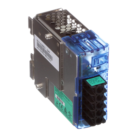
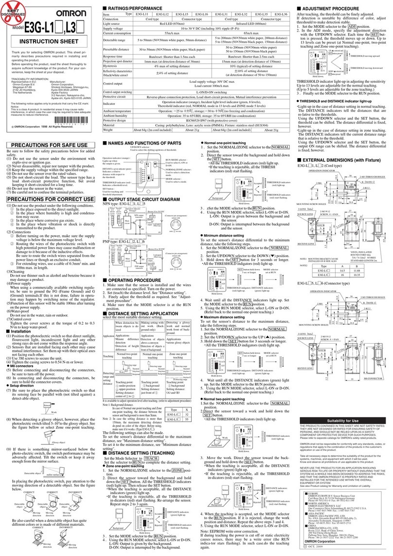
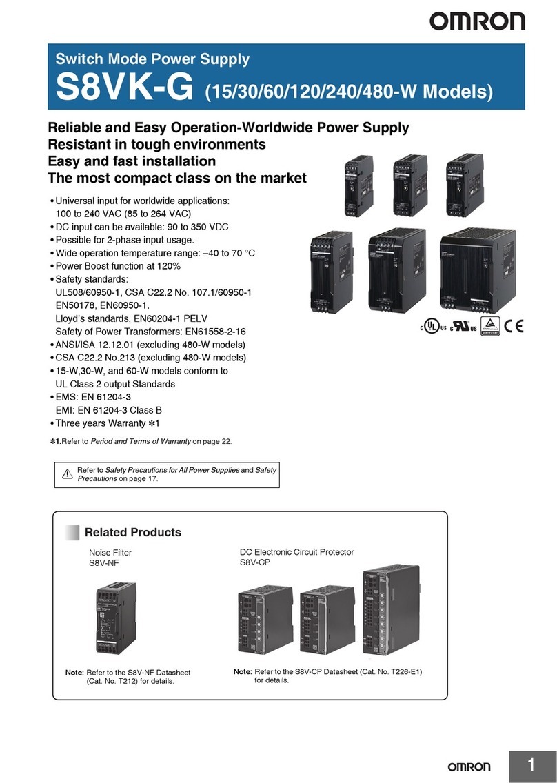
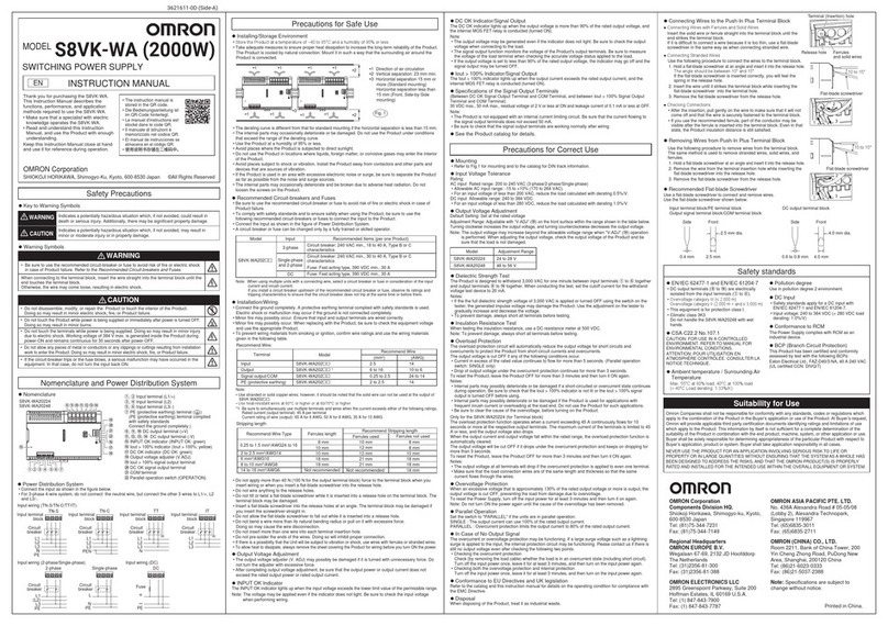
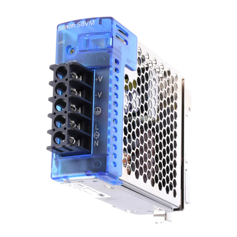
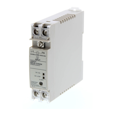
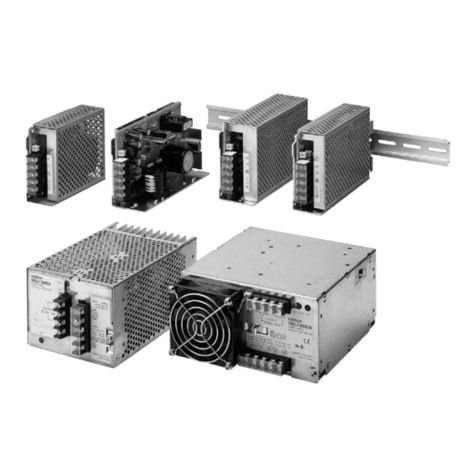
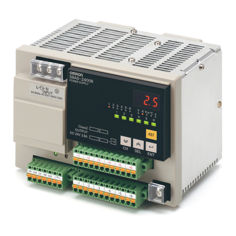
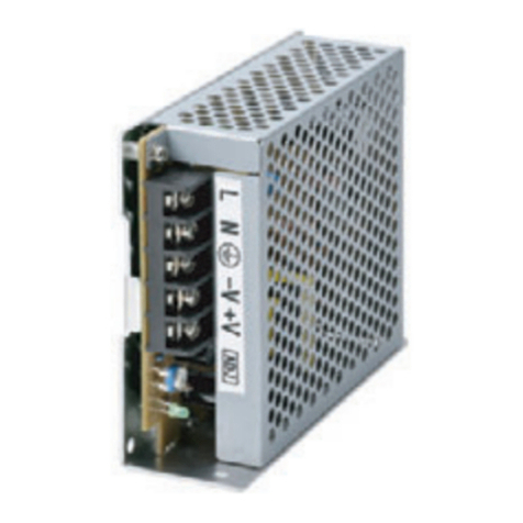
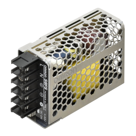
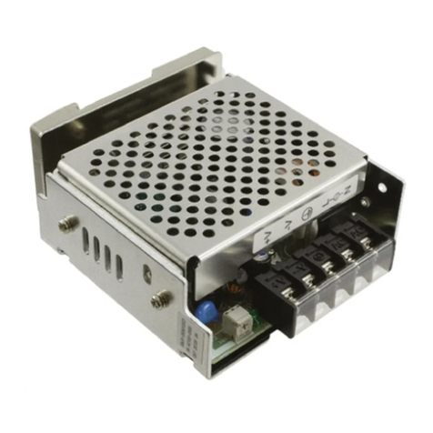
Omron S8JX-G Series User manual

New Product
1
S8JX-PS8JX-G
Common Precautions
Switch Mode Power Supply
S8JX (15/35/50/100/150/300/600-W Models)
Easy-to-use, Widely range from 15 W to 600 W (Output Voltage: 5 V to 48V)
• Easy Mounting:
Front-mounted type, DIN rail-mounted type are
available.
Screw-mount at the top. (except 300-/600-W models)
• Safety standards:
UL 508/60950-1
cUL CSA C22.2 No. 107.1
cUR CSA C22.2 No. 60950-1
EN 50178 (= VDE 0160) Over voltage
category III
EN 60950-1 (= VDE 0805 Teil 1)
• EMC: Conforms to EN 61204-3.
(EMI:EN55011 ClassA)
• Input conditions:
The input voltage range of 15-W, 35-W,
50-W, 100-W, and 150-W models has
been increased to 80 to 370 VDC (EC
Directives and safety standards do not
apply.).
S8JX-P Series with EMI ClassB and Power Factor Correction is newly
added to S8JX Series.
(Applicable to all capacities from 50 W to 600 W)
• Limits for harmonic current emissions (conforms to
EN61000-3-2)
• Conforms to EMI EN55011 Class B
• Applicable to input free voltage: 100 to 240 VAC
• Extended DC input voltage range: 80 to 370 VDC
*DC input is not subject to EC directives and safety standards.
• Easy mounting: Front-mounting bracket type and
DIN-Rail mounting type are included
as standard with the product.
Screw-mount at the top.
(except 300-/600-W models)
• Safety standards
- UL508/60950-1, cUL CSA C22.2 No.107.1,
cUR CSA C22.2 No.60950-1
- EN50178 (=VDE0160) Over voltage category III
EN60950-1 (=VDE0805 Teil1)
<Applicable only for 300 W and 600 W>
• High capacity application-covered functions are
included as standard with the product.
• Alarm detection function, Remote control function,
Remote sensing function
S8JX-G Series
S8JX-P Series
For the most recent information on models that have been certified for
safety standards, refer to your OMRON website.
For the most recent information on models that have been certified for
safety standards, refer to your OMRON website.
Refer to Safety Precautions on page 55.

S8JX
2
S8JX-G S8JX-P
Common Precautions
Model Number Structure
Model Number Legend
Note: Not all combinations are possible. Refer to List of Models in Ordering Information on page 3.
1. Power Ratings
015: 15 W
035: 35 W
050: 50 W
100: 100 W
150: 150 W
2. Output Voltage
05: 5 V
12: 12 V
15: 15 V
24: 24 V
48: 48 V
3. Configuration (15/35/50/100/150 W model)
None: Open type
C: Covered
4. Configuration/mounting
None: Front-mounting
D: DIN Rail-mounting
1. Power Ratings
300: 300 W
600: 600 W
2. Output Voltage
05: 5V
12: 12 V
24: 24 V
48: 48 V
3. Configuration/mounting (covered type)
C: Front-mounting
CD: DIN Rail-mounting
Note: Estimates can be provided for coatings and other specifications that are not given in the datasheet. Ask your OMRON representative for details.
15-/35-/50-/100-/150-W Models
1234
S8JX-G@@@@@@@
300-/600-W Models
1 2 3
S8JX-G@@@@@@

S8JX
3
S8JX-G S8JX-P
Common Precautions
Ordering Information
List of Models
Note: For details on normal stock models, contact your nearest OMRON representative.
*The range for compliance with EC Directives and safety standards (UL, EN, etc.) is 100 to 240 VAC (85 to 264 VAC).
Configuration Input voltage Power ratings
Output voltage
(VDC)
Output current Built-in fan Model
Covered Power
Supplies
100 to 240 VAC
(free)
(80 to 370 VDC *)
S8JX-G15005@@:
Switchable between 100
to 120 VAC and 200 to
240 VAC. (DC power
cannot be input.)
15 W
5 V 3 A
No
S8JX-G01505CD
12 V 1.3 A S8JX-G01512CD
15 V 1 A S8JX-G01515CD
24 V 0.65 A S8JX-G01524CD
48 V 0.35 A S8JX-G01548CD
35 W
5 V 7 A S8JX-G03505CD
12 V 3 A S8JX-G03512CD
15 V 2.4 A S8JX-G03515CD
24 V 1.5 A S8JX-G03524CD
48 V 0.75 A S8JX-G03548CD
50 W
5 V 10 A S8JX-G05005CD
12 V 4.2 A S8JX-G05012CD
24 V 2.1 A S8JX-G05024CD
48 V 1.1 A S8JX-G05048CD
100 W
5 V 20 A S8JX-G10005CD
12 V 8.5 A S8JX-G10012CD
24 V 4.5 A S8JX-G10024CD
48 V 2.1 A S8JX-G10048CD
150 W
5 V 30 A S8JX-G15005CD
12 V 13 A S8JX-G15012CD
24 V 6.5 A S8JX-G15024CD
48 V 3.3 A S8JX-G15048CD
100 to 120 VAC
200 to 240 VAC
(Switchable) 300 W
5 V 60 A Yes S8JX-G30005CD
12 V 27 A S8JX-G30012CD
24 V 14A No S8JX-G30024CD
48 V 7A S8JX-G30048CD
Configuration Input voltage Power ratings
Output voltage
(VDC)
Output current Built-in fan Model
Open type Power
Supplies
100 to 240 VAC
(free)
(80 to 370 VDC *)
S8JX-G15005@@:
Switchable between 100
to 120 VAC and 200 to
240 VAC. (DC power
cannot be input.)
15 W
5 V 3 A
No
S8JX-G01505D
12 V 1.3 A S8JX-G01512D
15 V 1 A S8JX-G01515D
24 V 0.65 A S8JX-G01524D
48 V 0.35 A S8JX-G01548D
35 W
5 V 7 A S8JX-G03505D
12 V 3 A S8JX-G03512D
15 V 2.4 A S8JX-G03515D
24 V 1.5 A S8JX-G03524D
48 V 0.75 A S8JX-G03548D
50 W
5 V 10 A S8JX-G05005D
12 V 4.2 A S8JX-G05012D
24 V 2.1 A S8JX-G05024D
48 V 1.1 A S8JX-G05048D
100 W
5 V 20 A S8JX-G10005D
12 V 8.5 A S8JX-G10012D
24 V 4.5 A S8JX-G10024D
48 V 2.1 A S8JX-G10048D
150 W
5 V 30 A S8JX-G15005D
12 V 13 A S8JX-G15012D
24 V 6.5 A S8JX-G15024D
48 V 3.3 A S8JX-G15048D
DIN Rail-mounting *
DIN Rail-mounting *

S8JX
4
S8JX-G S8JX-P
Common Precautions
*The range for compliance with EC Directives and safety standards (UL, EN, etc.) is 100 to 240 VAC (85 to 264 VAC).
Configuration Input voltage Power ratings
Output voltage
(VDC)
Output current Built-in fan
Front-
mounting
bracket
Model
Covered Power
Supplies
100 to 240 VAC
(free)
(80 to 370 VDC *)
S8JX-G15005@@:
Switchable between 100
to 120 VAC and 200 to
240 VAC. (DC power
cannot be input.)
15 W
5 V 3 A
No Provided
S8JX-G01505C
12 V 1.3 A S8JX-G01512C
15 V 1 A S8JX-G01515C
24 V 0.65 A S8JX-G01524C
48 V 0.35 A S8JX-G01548C
35 W
5 V 7 A S8JX-G03505C
12 V 3 A S8JX-G03512C
15 V 2.4 A S8JX-G03515C
24 V 1.5 A S8JX-G03524C
48 V 0.75 A S8JX-G03548C
50 W
5 V 10 A S8JX-G05005C
12 V 4.2 A S8JX-G05012C
24 V 2.1 A S8JX-G05024C
48 V 1.1 A S8JX-G05048C
100 W
5 V 20 A S8JX-G10005C
12 V 8.5 A S8JX-G10012C
24 V 4.5 A S8JX-G10024C
48 V 2.1 A S8JX-G10048C
150 W
5 V 30 A S8JX-G15005C
12 V 13 A S8JX-G15012C
24 V 6.5 A S8JX-G15024C
48 V 3.3 A S8JX-G15048C
100 to 120 VAC
200 to 240 VAC
(Switchable)
300 W
5 V 60 A Yes
No
S8JX-G30005C
12 V 27 A S8JX-G30012C
24 V 14A No S8JX-G30024C
48 V 7A S8JX-G30048C
600 W
5 V 120A
Yes
S8JX-G60005C
12 V 53A S8JX-G60012C
24 V 27A S8JX-G60024C
48 V 13A S8JX-G60048C
Front-mounting *

S8JX
5
S8JX-G S8JX-P
Common Precautions
*The range for compliance with EC Directives and safety standards (UL, EN, etc.) is 100 to 240 VAC (85 to 264 VAC).
Configuration Input voltage Power ratings
Output voltage
(VDC)
Output current Built-in fan
Front-
mounting
bracket
Model
Open type Power
Supplies
100 to 240 VAC
(free)
(80 to 370 VDC *)
S8JX-G15005@@:
Switchable between 100
to 120 VAC and 200 to
240 VAC. (DC power
cannot be input.)
15 W
5 V 3 A
No Provided
S8JX-G01505
12 V 1.3 A S8JX-G01512
15 V 1 A S8JX-G01515
24 V 0.65 A S8JX-G01524
48 V 0.35 A S8JX-G01548
35 W
5 V 7 A S8JX-G03505
12 V 3 A S8JX-G03512
15 V 2.4 A S8JX-G03515
24 V 1.5 A S8JX-G03524
48 V 0.75 A S8JX-G03548
50 W
5 V 10 A S8JX-G05005
12 V 4.2 A S8JX-G05012
24 V 2.1 A S8JX-G05024
48 V 1.1 A S8JX-G05048
100 W
5 V 20 A S8JX-G10005
12 V 8.5 A S8JX-G10012
24 V 4.5 A S8JX-G10024
48 V 2.1 A S8JX-G10048
150 W
5 V 30 A S8JX-G15005
12 V 13 A S8JX-G15012
24 V 6.5 A S8JX-G15024
48 V 3.3 A S8JX-G15048
Front-mounting *

S8JX
6
S8JX-G S8JX-P
Common Precautions
Ratings, Characteristics, and Functions
*1. When a load is connected that has a built-in DC-DC converter, the overload protection may operate at startup and the Power Supply may not
start. Refer to Overload Protection on page 20.
*2. Do not use an Inverter output for the Power Supply. Inverters with an output frequency of 50/60 Hz are available, but the rise in the internal
temperature of the Power Supply may result in ignition or burning.
*3. Rated input voltage: 100 or 200 VAC at 100% load.
*4. Output characteristics: Specified at power supply output terminals.
*5. If the output voltage adjuster (V. ADJ) is turned, the voltage will increase by more than the allowable voltage range. When adjusting the output
voltage, confirm the actual output voltage from the Power Supply and be sure that load is not damaged.
*6. For details, refer to Overload Protection on page 20.
*7. To reset the protection, turn OFF the input power for seven minutes or longer and then turn it back ON.
*8. The weight indicated is for Front-mounting, Open-frame Power Supply.
*9. The range for compliance with EC Directives and safety standards (UL, EN, etc.) is 100 to 240 VAC (85 to 264 VAC).
Input specification 100 to 240 V input
Item Power ratings *115 W 35 W
Efficiency 68% min. 73% min.
Input
Voltage *2100 to 240 VAC (allowable range: 85 to 264 VAC, 80 to 370 VDC *9)
Frequency *250/60 Hz (47 to 450 Hz)
Current *3100 V input 0.4 A max. 1 A max.
200 V input 0.25 A max. 0.6 A max.
Harmonic current emissions ---
Leakage current *3100 V input 0.5 mA max.
200 V input 1 mA max.
Inrush current (for a
cold start at 25°C) *3
100 V input 20 A max.
200 V input 40 A max.
Output *4
Voltage adjustment range *5−10% to 15% (with V. ADJ) (48-V models: ±10%)
Ripple *32% (p-p) max.
Input variation influence 0.4% max. with AC input voltage
Load variation influence 0.8% max. (0 to 100% load, rated input voltage)
Temperature variation influence 0.05%/°C max. (at rated input and output)
Startup time 500 ms max. (up to 90% of output voltage at rated input and output)
Hold time *320 ms min.
Additional
functions
Overload protection *6105% to 175% of rated load current, voltage drop, intermittent, automatic reset
Overvoltage protection *7Yes
Overheat protection No
Parallel operation No (However, backup operation is possible; external diodes required.)
Series operation Yes (For up to two Power Supplies; external diodes required.)
Protective circuit operation indicator No
Other
Ambient operating temperature Refer to the derating curve in Engineering Data on page 17 (with no icing or
condensation).
Storage temperature −25 to 65°C (with no icing or condensation)
Ambient operating humidity 25% to 85% (Storage humidity: 25% to 90%)
Dielectric strength
3.0 kVAC for 1 min. (between all inputs and outputs; detection current: 20 mA)
2.0 kVAC for 1 min. (between all inputs and PE terminals; detection current: 20 mA)
1.0 kVAC for 1 min. (between all outputs and PE terminals; detection current: 20 mA)
Insulation resistance 100 MΩmin. (between all outputs and all inputs/PE terminals) at 500 VDC
Vibration resistance 10 to 55 Hz, 0.375-mm single amplitude for 2 h each in X, Y, and Z directions
Shock resistance 150 m/s2, 3 times each in ±X, ±Y, ±Z directions
Output indicator Yes (Color: Green)
EMI Conducted Emissions Conforms to EN 55011 Group 1 Class A and based on FCC Class A *9
Radiated Emissions Conforms to EN 55011 Group 1 Class A *9
EMS
Electrostatic Discharge Conforms to EN61000-4-2
Radiated Electromagnetic Field Conforms to EN61000-4-3
Electrical Fast Transient/Burst Conforms to EN61000-4-4
Surge Conforms to EN61000-4-5
Conducted Disturbance Conforms to EN61000-4-6
Voltage Dips/Short Interruptions Conforms to EN61000-4-11
Approved standards *9
UL Listed: UL 508 (Listing), UL UR: UL 60950-1 (Recognition)
cUL Listed: CSA C22.2 No.107.1
cUR: CSA C22.2 No. 60950-1
EN/VDE: EN50178 (= VDE 0160) Over voltage category III, EN 60950-1 (= VDE 0805 Teil 1)
(Terminal block: Based on DIN 50274 (VDE 0660-514))
SEMI SEMI F47-0200 (200-VAC input)
Weight *8250 g max.

S8JX
7
S8JX-G S8JX-P
Common Precautions
*1. When a load is connected that has a built-in DC-DC converter, the overload protection may operate at startup and the Power Supply may not
start. Refer to Overload Protection on page 20.
*2. Do not use an Inverter output for the Power Supply. Inverters with an output frequency of 50/60 Hz are available, but the rise in the internal
temperature of the Power Supply may result in ignition or burning.
*3. Rated input voltage: 100 or 200 VAC at 100% load.
*4. Output characteristics: Specified at power supply output terminals.
*5. If the output voltage adjuster (V. ADJ) is turned, the voltage will increase by more than the allowable voltage range. When adjusting the output
voltage, confirm the actual output voltage from the Power Supply and be sure that load is not damaged.
*6. For details, refer to Overload Protection on page 20.
*7. To reset the protection, turn OFF the input power for seven minutes or longer and then turn it back ON.
*8. The weight indicated is for Front-mounting, Open-frame Power Supply.
*9. The range for compliance with EC Directives and safety standards (UL, EN, etc.) is 100 to 240 VAC (85 to 264 VAC).
Input specification 100 to 240 V input
Item Power ratings *150 W 100 W
Efficiency
5 V Models 76% min. 76% min.
12 V Models 81% min. 81% min.
24 V Models 83% min. 83% min.
48V Models 82% min. 83% min.
Input
Voltage *2100 to 240 VAC (allowable range: 85 to 264 VAC, 80 to 370 VDC *9)
Frequency *250/60 Hz (47 to 450 Hz)
Current *3100 V input 1.4 A max. 2.5 A max.
200 V input 0.8 A max. 1.5 A max.
Harmonic current emissions ---
Leakage current *3100 V input 0.5 mA max.
200 V input 1 mA max.
Inrush current (for a
cold start at 25°C) *3
100 V input 20 A max.
200 V input 40 A max.
Output *4
Voltage adjustment range *5−10% to 15% (with V. ADJ) (48-V models: ±10%)
Ripple *32% (p-p) max.
Input variation influence 0.4% max. (with AC input voltage)
Load variation influence 0.8% max. (0 to 100% load, rated input voltage)
Temperature variation influence 0.05%/°C max. (at rated input and output)
Startup time 500 ms max. (up to 90% of output voltage at rated input and output)
Hold time *320 ms min.
Additional
functions
Overload protection *6105% to 175% of rated load current, voltage drop, intermittent, automatic reset
Overvoltage protection *7Yes
Overheat protection No
Parallel operation No (However, backup operation is possible; external diodes required.)
Series operation Yes (For up to two Power Supplies; external diodes required.)
Protective circuit operation indicator No
Other
Ambient operating temperature Refer to the derating curve in Engineering Data on page 17 (with no icing or
condensation).
Storage temperature −25 to 65°C (with no icing or condensation)
Ambient operating humidity 25% to 85% (Storage humidity: 25% to 90%)
Dielectric strength
3.0 kVAC for 1 min. (between all inputs and outputs; detection current: 20 mA)
2.0 kVAC for 1 min. (between all inputs and PE terminals; detection current: 20 mA)
1.0 kVAC for 1 min. (between all outputs and PE terminals; detection current: 20 mA)
Insulation resistance 100 MΩmin. (between all outputs and all inputs/PE terminals) at 500 VDC
Vibration resistance 10 to 55 Hz, 0.375-mm single amplitude for 2 h each in X, Y, and Z directions
Shock resistance 150 m/s2, 3 times each in ±X, ±Y, ±Z directions
Output indicator Yes (Color: Green)
EMI Conducted Emissions Conforms to EN 55011 Group 1 Class A and based on FCC Class A *9
Radiated Emissions Conforms to EN 55011 Group 1 Class A *9
EMS
Electrostatic Discharge Conforms to EN61000-4-2
Radiated Electromagnetic Field Conforms to EN61000-4-3
Electrical Fast Transient/Burst Conforms to EN61000-4-4
Surge Conforms to EN61000-4-5
Conducted Disturbance Conforms to EN61000-4-6
Voltage Dips/Short Interruptions Conforms to EN61000-4-11
Approved standards *9
UL Listed: UL 508 (Listing), UL UR: UL 60950-1 (Recognition)
cUL Listed: CSA C22.2 No.107.1
cUR: CSA C22.2 No. 60950-1
EN/VDE: EN50178 (= VDE 0160) Over voltage category III, EN 60950-1 (= VDE 0805 Teil 1)
(Terminal block: Based on DIN 50274 (VDE 0660-514))
SEMI SEMI F47-0200 (200-VAC input)
Weight *8300 g max. 550 g max.

S8JX
8
S8JX-G S8JX-P
Common Precautions
*1. When a load is connected that has a built-in DC-DC converter, the overload protection may operate at startup and the Power Supply may not
start. Refer to Overload Protection on page 20.
*2. Do not use an Inverter output for the Power Supply. Inverters with an output frequency of 50/60 Hz are available, but the rise in the internal
temperature of the Power Supply may result in ignition or burning.
*3. Rated input voltage: 100 or 200 VAC at 100% load.
*4. Output characteristics: Specified at power supply output terminals.
*5. If the output voltage adjuster (V. ADJ) is turned, the voltage will increase by more than the allowable voltage range. When adjusting the output
voltage, confirm the actual output voltage from the Power Supply and be sure that load is not damaged.
*6. For details, refer to Overload Protection on page 20.
*7. To reset the protection, turn OFF the input power for seven minutes or longer and then turn it back ON.
*8. The weight indicated is for Front-mounting, Open-frame Power Supply.
*9. The range for compliance with EC Directives and safety standards (UL, EN, etc.) is 100 to 240 VAC (85 to 264 VAC).
Input specification 100/200 V switchable 100 to 240 V input
Item Power ratings *1150 W at 5 V 150 W at 12 V 150 W at 24 or 48V
Efficiency
5 V Models 78% min. --- ---
12 V Models --- 79% min. ---
24 V Models --- --- 86% min.
48V Models --- --- 85% min.
Input
Voltage *2
Switchable between 100 to
120 VAC (allowable range:
85 to 132 VAC) and 200 to
240 VAC (allowable range:
170 to 264 VAC).
100 to 240 VAC
(allowable range: 85 to 264 VAC, 80 to 370 VDC *9)
Frequency *250/60 Hz (47 to 450 Hz)
Current *3100 V input 3.5 A max. 3.6 A max. 3.5 A max.
200 V input 2.1 A max. 2.2 A max. 2.1 A max.
Harmonic current emissions ---
Leakage current *3100 V input 0.5 mA max.
200 V input 1 mA max.
Inrush current (for a
cold start at 25°C) *3
100 V input 20 A max.
200 V input 40 A max.
Output *4
Voltage adjustment range *5−10% to 15% (with V. ADJ) (48-V models: ±10%)
Ripple *32% (p-p) max.
Input variation influence 0.4% max. (with AC input voltage)
Load variation influence 0.8% max. (0 to 100% load, rated input voltage)
Temperature variation influence 0.05%/°C max. (at rated input and output)
Startup time 500 ms max. (up to 90% of output voltage at rated input and output)
Hold time *320 ms min.
Additional
functions
Overload protection *6
105% to 175% of rated load
current, voltage drop,
automatic reset
105% to 175% of rated load current, voltage drop,
intermittent, automatic reset
Overvoltage protection *7Yes
Overheat protection No
Parallel operation No (However, backup operation is possible; external diodes required.)
Series operation Yes (For up to two Power Supplies; external diodes required.)
Protective circuit operation indicator No
Other
Ambient operating temperature Refer to the derating curve in Engineering Data on page 17 (with no icing or
condensation).
Storage temperature −25 to 65°C (with no icing or condensation)
Ambient operating humidity 25% to 85% (Storage humidity: 25% to 90%)
Dielectric strength
3.0 kVAC for 1 min. (between all inputs and outputs; detection current: 20 mA)
2.0 kVAC for 1 min. (between all inputs and PE terminals; detection current: 20 mA)
1.0 kVAC for 1 min. (between all outputs and PE terminals; detection current: 20 mA)
Insulation resistance 100 MΩmin. (between all outputs and all inputs/PE terminals) at 500 VDC
Vibration resistance 10 to 55 Hz, 0.375-mm single amplitude for 2 h each in X, Y, and Z directions
Shock resistance 150 m/s2, 3 times each in ±X, ±Y, ±Z directions
Output indicator Yes (Color: Green)
EMI Conducted Emissions Conforms to EN 55011 Group 1 Class A and based on FCC Class A *9
Radiated Emissions Conforms to EN 55011 Group 1 Class A *9
EMS
Electrostatic Discharge Conforms to EN61000-4-2
Radiated Electromagnetic Field Conforms to EN61000-4-3
Electrical Fast Transient/Burst Conforms to EN61000-4-4
Surge Conforms to EN61000-4-5
Conducted Disturbance Conforms to EN61000-4-6
Voltage Dips/Short Interruptions Conforms to EN61000-4-11
Approved standards *9
UL Listed: UL 508 (Listing), UL UR: UL 60950-1 (Recognition)
cUL Listed: CSA C22.2 No.107.1
cUR: CSA C22.2 No. 60950-1
EN/VDE: EN50178 (= VDE 0160), Over voltage category III, EN 60950-1 (= VDE 0805 Teil 1)
(Terminal block: Based on DIN 50274 (VDE 0660-514))
SEMI --- SEMI F47-0200 (200-VAC input)
Weight *8800 g max. 700 g max. 600 g max.
S8JX
9
S8JX-G S8JX-P
Common Precautions
Input specification 100/200 V (Selected)
Item Power ratings *1300 W 600 W
Efficiency
5 V models 71% min. 72% min.
12 V models 75% min. 78% min.
24 V models 82% min. 80% min.
48V models 82% min. 80% min.
Input
Voltage *2
100 to 120 VAC (allowable range: 85 to 132 VAC)
200 to 240 VAC (allowable range: 170 to 264 VAC)
(Switchable)
Frequency *250/60 Hz (47 to 450 Hz)
Current *3
100 V input 8Amax. 16 A max.(5V, 12V, 48V)
14 A max.(24V)
200 V input 4.5 A max. 9 A max.(5V, 12V, 48V)
8 A max.(24V)
Harmonic current emissions ---
Leakage current *3100 V input 0.5 mA max.
200 V input 1 mA max.
Inrush current (for a
cold start at 25°C) *3
100 V input 25 A max. 30 A max.
200 V input 50 A max. 60 A max.
Output *4
Voltage adjustment range *5−10% to 15% (with V. ADJ) (48-V models: ±10%)
Ripple *32.8% (p-p) max.(5V) *6
2% (p-p) max.(12V, 24V, 48V)
3.8% (p-p) max.(5V) *6
2% (p-p) max.(12V) *6
2% (p-p) max.(24V, 48V)
Input variation influence 0.4% max.
Load variation influence 0.8% max. (0 to 100% load, rated input voltage)
Temperature variation influence 0.05%/°C max.
Startup time 650 ms max. 500 ms max.
Hold time *320 ms min.
Additional
functions
Overload protection *7
105% to 175%
of rated load current, Inverted L voltage drop,
the circuit will be shut OFF when the
overload exceeds 5 s.
(5V, 12V)
*
10
voltage drop, intermittent, automatic reset.
(24V, 48V)
105% to 175% of rated load current, Inverted
L voltage drop, the circuit will be shut OFF
when the overload exceeds 5 s.
*
10
Overvoltage protection *8Yes (5V, 12V)
*
10
Yes (24V, 48V)
*
10
Yes *10
Overheat protection Yes (5V, 12V)
*
10
N0 (24V, 48V)
*
10
Yes *10
Parallel operation Yes (up to 5 units)
Series operation Yes (For up to two Power Supplies; external diodes required.)
Protective circuit operation indicator Yes (color: red) (5V, 12V)
No (24V, 48V)
Yes (color: red)
Other
Ambient operating temperature
Refer to the derating curve in Engineering Data on page 17 (with no icing or condensation).
Storage temperature −25 to 65°C (with no icing or condensation)
Ambient operating humidity 25% to 85% (Storage humidity: 25% to 90%)
Dielectric strength
3.0 kVAC for 1 min. (between all inputs and outputs; detection current: 25 mA)
2.0 kVAC for 1 min. (between all inputs and PE terminals; detection current: 25 mA)
1.0 kVAC for 1 min. (between all outputs and PE terminals; detection current: 25 mA)
Insulation resistance 100 MΩmin. (between all outputs and all inputs/PE terminals) at 500 VDC
Vibration resistance 10 to 55 Hz, 0.375-mm single amplitude for 2 h each in X, Y, and Z directions
Shock resistance 150 m/s2, 3 times each in ±X, ±Y, ±Z directions
Output indicator Yes (Color: Green)
EMI Conducted Emissions *3Conforms to EN 55011 Group 1 Class A and based on FCC Class A
*
11
Radiated Emissions Conforms to EN 55011 Group 1 Class A
*
11
*
12
EMS
Electrostatic Discharge Conforms to EN61000-4-2
Radiated Electromagnetic Field Conforms to EN61000-4-3
Electrical Fast Transient/Burst Conforms to EN61000-4-4
Surge Conforms to EN61000-4-5
Conducted Disturbance Conforms to EN61000-4-6
Voltage Dips/Short Interruptions Conforms to EN61000-4-11
Approved standards *13
UL UR: UL 508 (Recognition), UL 60950-1 (Recognition)
cUR: CSA C22.2 No. 60950-1
EN/VDE: EN50178 (= VDE 0160), Over voltage category III, EN 60950-1 (= VDE 0805 Teil 1)
(Terminal block: Based on DIN 50274 (VDE 0660-514))
Weight *91,800 g max. (5V, 12V)
1,600 g max. (24V, 48V) 2,500 g max.
S8JX
10
S8JX-G S8JX-P
Common Precautions
*1. When a load is connected that has a built-in DC-DC converter, the overload protection may operate at startup and the Power Supply may not
start. Refer to Overload Protection on page 20.
*2. Do not use an Inverter output for the Power Supply. Inverters with an output frequency of 50/60 Hz are available, but the rise in the internal
temperature of the Power Supply may result in ignition or burning.
*3. Rated input voltage: 100 or 200 VAC at 100% load.
*4. Output characteristics: Specified at power supply output terminals.
*5. If the output voltage adjuster (V. ADJ) is turned, the voltage will increase by more than the allowable voltage range. When adjusting the output
voltage, confirm the actual output voltage from the Power Supply and be sure that load is not damaged.
*6. Measurement methods are based on JEITA standard RC-9131A. Refer to Ripple Noise Voltage on page 57.
*7. For details, refer to Overload Protection on page 20.
*8. To reset the protection, turn OFF the input power for three minutes or longer and then turn it back ON.
*9. The weight indicated is for Front-mounting Power Supply.
*10.The protection-ON alarm indicator will light as soon as the output is interrupted. For resetting, turn OFF the input power, leave for more than
three minutes , and then turn it back ON again.
*11.Noise values depend on the wiring methods and other factors. Insert noise filters and cores in the input and output lines.
300 W, 5 V: Two E04SR401938 (manufactured by SEIWA) on the output line.
300 W, 12 V: One E04SR401938 (manufactured by SEIWA) on the output line.
600 W, 5 V or 12 V: One FN2450G-16-61 (manufactured by Schaffner) on the input line.
One E04RC613620 (manufactured by SEIWA) on the output line.
*12.For the 600-W, 5-V and 12-V models, class A compliance was met with an aluminum plate placed under the Power Supply.
*13.The range for compliance with EC Directives and safety standards (UL, EN, etc.) is 100 to 240 VAC (85 to 264 VAC).

S8JX
11
S8JX-G S8JX-P
Common Precautions
Connections
Block Diagrams
Voltage
detection
Photocoupler
Drive control
Circuit
Overcurrent
detection
circuit
+V
−V
DC OUTPUT
Noise
filter
Inrush current
protection
Fuse
2.0 A
AC (L)
INPUT
AC (N)
Rectifier Smoothing
circuit
Rectifier/
Smoothing circuit
Overvoltage
detection circuit
S8JX-G01505@@ (15 W)
S8JX-G01512@@ (15 W)
S8JX-G01515@@ (15 W)
S8JX-G01524@@ (15 W)
Voltage
detection circuit
Photocoupler
Overvoltage
detection circuit
Drive control
circuit
Overcurrent
detection
circuit
+V
−V
DC OUTPUT
Rectifier/
smoothing circuit
Noise
filter
Inrush current
protection
Fuse:
2.0 A
AC (L)
INPUT
AC (N)
Rectifier Smoothing
circuit
S8JX-G01548@@ (15 W)
Voltage
detection
Photocoupler
Drive control
Circuit
Overcurrent
detection
circuit
+V
−V
DC OUTPUT
Noise
filter
Inrush current
protection
Fuse
3.15 A
AC (L)
INPUT
AC (N)
Rectifier Smoothing
circuit
Rectifier/
Smoothing circuit
Overvoltage
detection circuit
S8JX-G03505@@ (35 W)
S8JX-G03512@@ (35 W)
S8JX-G03515@@ (35 W)
S8JX-G03524@@ (35 W)
Voltage
detection circuit
Photocoupler
Overvoltage
detection circuit
Drive control
circuit
Overcurrent
detection
circuit
+V
−V
DC OUTPUT
Rectifier/
smoothing circuit
Noise
filter
Inrush current
protection
Fuse:
3.15 A
AC (L)
INPUT
AC (N)
Rectifier Smoothing
circuit
S8JX-G03548@@ (35 W)

S8JX
12
S8JX-G S8JX-P
Common Precautions
Voltage
detection
Photocoupler
Drive control
Circuit
Overcurrent
detection
circuit
+V
−V
DC OUTPUT
Noise
filter
Inrush current
protection
Fuse
6.3 A
AC (L)
INPUT
AC (N)
Rectifier Smoothing
circuit
Rectifier/
Smoothing circuit
Overvoltage
detection circuit
S8JX-G05005@@ (50 W)
S8JX-G05012@@ (50 W)
S8JX-G05024@@ (50 W)
Voltage
detection circuit
Photocoupler
Overvoltage
detection circuit
Drive control
circuit
Overcurrent
detection
circuit
+V
−V
DC OUTPUT
Rectifier/
smoothing circuit
Noise
filter
Inrush current
protection
Fuse:
6.3 A
AC (L)
INPUT
AC (N)
Rectifier Smoothing
circuit
S8JX-G05048@@ (50 W)
DC OUTPUT
INPUT
Voltage
detection
+V
−V
Noise
filter
Inrush current
protection
Fuse
8A
AC (L)
AC (N)
Rectifier
Photocoupler
Drive control
Circuit
Overcurrent
detection
circuit
Smoothing
circuit Rectifier/
Smoothing circuit
Overvoltage
detection circuit
S8JX-G100@@@@ (100 W)

S8JX
13
S8JX-G S8JX-P
Common Precautions
Voltage
detection circuit
Photocoupler
Input voltage switch
100/200 Vswitching
Overvoltage
detection circuit
Noise
filter
Fuse:
8A
AC (L)
INPUT
AC (N)
Drive control
circuit
Overcurrent
detection
circuit
+V
−V
DC OUTPUT
Inrush current protection Rectifier/
smoothing circuit
Rectifier/
smoothing circuit
S8JX-G15005@@ (150 W)
Note: Set the input voltage switch to "115V" for 100 to 120 VAC and to "230V" for 200 to 240 VAC.
INPUT DC OUTPUT
Voltage
detection
+V
−V
Noise
filter
Inrush current
protection
Fuse
10 A
AC (L)
AC (N)
Rectifier
Photocoupler
Drive control
Circuit
Overcurrent
detection
circuit
Smoothing
circuit
Overvoltage
detection circuit
Rectifier/
Smoothing circuit
S8JX-G15012@@ (150 W)
S8JX-G15024@@ (150 W)
S8JX-G15048@@ (150 W)
INPUT DC OUTPUT
Voltage
detection
+V
−V
Noise
filter
Inrush current protection
Fuse
10 A
AC (L)
AC (N)
Photocoupler
Drive control
Circuit
Overcurrent
detection
circuit
Overvoltage
detection circuit
Rectifier/Smoothing circuit
Rectifier/
Smoothing circuit
Parallel operation selector
100/200V(Selectable)
Rectifier/Smoothing circuit
Fan
Overheat
detection circuit
Overheat
detection
circuit
S8JX-G30005@@ (300 W)
S8JX-G30012@@ (300 W)
Note: Short-circuit the input voltage selector terminals if the input is 100 to 120 VAC.
Keep the terminals open if the input is 200 to 240 VAC.

S8JX
14
S8JX-G S8JX-P
Common Precautions
INPUT DC OUTPUT
Voltage
detection
+V
−V
Noise
filter
Inrush current protection
Fuse
10 A
AC (L)
AC (N)
Photocoupler
Drive control
Circuit
Overcurrent
detection
circuit
Overvoltage
detection circuit
Rectifier/
Smoothing circuit
Rectifier/
Smoothing circuit
Parallel operation selector
100/200V(Selectable)
S8JX-G30024@@ (300 W)
S8JX-G30048@@ (300 W)
Note: Short-circuit the input voltage selector terminals if the input is 100 to 120 VAC.
Keep the terminals open if the input is 200 to 240 VAC.
AC(L)
INPUT
AC(N)
DC OUTPUT
Fan
Voltage
detection
Overheat
detection circuit
+V
−V
Noise
filter
Inrush current protection
Fuse
20 A
Photocoupler
Control
Circuit
Overcurrent
detection
circuit
Overheat
detection
circuit
Overvoltage
detection circuit
Rectifier/
Smoothing circuit
Rectifier/
Smoothing circuit
Parallel operation selector
100/200V(Selectable)
Rectifier/Smoothing circuit
S8JX-G60005@ (600 W)
S8JX-G60012@ (600 W)
S8JX-G60048@ (600 W)
Note: Short-circuit the input voltage selector terminals if the input is 100 to 120 VAC.
Keep the terminals open if the input is 200 to 240 VAC.
Fan
INPUT DC OUTPUT
Voltage
detection
+V
−V
Noise
filter
Inrush current protection
Fuse
20 A
AC (L)
AC (N)
Photocoupler
Drive control
Circuit
Overcurrent
detection
circuit
Overheat
detection
circuit
Overvoltage
detection circuit
Rectifier/
Smoothing circuit
Rectifier/
Smoothing circuit
Parallel operation selector
100/200V(Selectable)
S8JX-G60024@ (600 W)
Note: Short-circuit the input voltage selector terminals if the input is 100 to 120 VAC.
Keep the terminals open if the input is 200 to 240 VAC.

S8JX
15
S8JX-G S8JX-P
Common Precautions
Construction and Nomenclature
Nomenclature
15-/35-/50-/100-/150-W Models
E
D
A
C
B
+V
−V
AC (L)
AC (N)
100 to 120 VAC 200 to 240 VAC
E
F
D
A
C
B
+V
−V
AC (L)
Bottom
AC (N)
*1. The fuse is located on the (L) side. It is NOT user-replaceable. For a DC
power input, connect the low side to the positive (+) terminal.
*2. This is the protective earth terminal specified in the safety standards.
Always ground this terminal.
*3. This item is applicable only to the S8JX-G15005@@.
No. Name Function
1DC Output
Terminals (−V), (+V)Connect the load lines to these terminals.
2AC Input Terminals
(L), (N)Connect the input lines to these terminals. *1
3Protective Earth
Terminal (PE) ( ) Connect the ground line to these terminals. *2
4Output Voltage
Adjuster (V. ADJ)
It is possible to increase or decrease the output
voltage.
5Output Indicator
(DC ON: Green) Lights green while a direct current (DC) output is ON.
6Input voltage switch
*3
Switches the internal circuits according to the input
voltage.
"115V": 100 to 120 VAC
"230V": 200 to 240 VAC
Note: The S8JX-G05024CD is
shown above.
Note: The S8JX-G15005C is shown
above.
+V
+V
−V
−V
AC(L)
AC(N)
Bottom
Note: The S8JX-G30005C is shown above.
*1. The fuse is located on the (L) side. It is NOT user-replaceable.
*2. This is the protective earth terminal specified in the safety standards.
Always ground this terminal.
*3. This is not applicable to 24-Vand 48-Vmodels.
No. Name Function
1DC Output
Terminals (+V), (−V)Connect the load lines to these terminals.
2AC Input Terminals
(L), (N)Connect the input lines to these terminals. *1
3Protective Earth
Terminal (PE) ( ) Connect the ground line to these terminals. *2
4Input Voltage
Selector Terminals
Short-circuit the terminals if the input is 100 to 120
VAC and open the terminals if the input is 200 to 240
VAC.
5Output Indicator
(DC ON: Green) Lights green while a direct current (DC) output is ON.
6Output Voltage
Adjuster (V. ADJ)
It is possible to increase or decrease the output
voltage.
7
Protection-ON
Alarm Indicator
(ALM: Red)
The red indicator will be lit if the overvoltage or
overheat protection circuit is triggered. This indicator
will also be lit when overload is detected. *3
8Selector of Parallel
Operation
Set the selector to PARALLEL if the Units are in
parallel operation.
300-W 24V, 48V Model
AC (L)
AC (N)
Bottom
+V
+V
−V
−V
E
F
D
C
H
AB
Note: The S8JX-G30024C is shown above.
300-W 5V, 12V Model 300-W Model

S8JX
16
S8JX-G S8JX-P
Common Precautions
Reference Values
Reliability (MTBF)
S8JX-G15012@@ and
S8JX-G15005@@ S8JX-G30005@@ and
S8JX-G300012@@ S8JX-G6000@@@ Other models
240,000 hrs 200,000 hrs 170,000 hrs 250,000 hrs
Definition
MTBF stands for Mean Time Between Failures, which is calculated according to the probability of accidental device
failures, and indicates reliability of devices.
Therefore, it does not necessarily represent a life of the product.
Life expectancy 10 yrs. min.
Definition The life expectancy indicates average operating hours under the ambient temperature of 40°C and a load rate of 50%.
Normally this is determined by the life expectancy of the built-in aluminum electrolytic capacitor.
Side
AC (L)
AC (N)
+V+V
−V−V
Note: The S8JX-G60005C
is shown above.
600-W 24V, 48V Model
AC (L)
AC (N)
Side
+V+V
−V−V
GEF
D
A
C
H
B
Note: The S8JX-G60024C
is shown above.
*1. The fuse is located on the (L) side. It is NOT user-replaceable.
*2. This is the protective earth terminal specified in the safety standards.
Always ground this terminal.
No. Name Function
1DC Output
Terminals (+V), (−V) Connect the load lines to these terminals.
2AC Input Terminals
(L), (N) Connect the input lines to these terminals. *1
3Protective Earth
Terminal (PE) ( ) Connect the ground line to these terminals. *2
4Input Voltage
Selector Terminals
Short-circuit the terminals if the input is 100 to 120
VAC and open the terminals if the input is 200 to 240
VAC.
5Output Indicator
(DC ON: Green) Lights green while a direct current (DC) output is ON.
6Output Voltage
Adjuster (V. ADJ) It is possible to increase or decrease the output
voltage.
7Protection-ON
Alarm Indicator
(ALM: Red)
The red indicator will be lit if the overvoltage or
overheat protection circuit is triggered. This indicator
will also be lit when overload is detected.
8Selector of Parallel
Operation Set the selector to PARALLEL if the Units are in
parallel operation.
600-W 5V, 12V Model 600-W Model

S8JX
17
S8JX-G S8JX-P
Common Precautions
Engineering Data
Derating Curves (Standard Mounting)
Open type Power Supplies Covered Power Supplies
Note: 1. Internal parts may occasionally deteriorate or be damaged. Do not use the Power Supply in areas outside the derating curve (i.e., the
area shown by shading in the above graph).
2. If there is a derating problem, use forced air-cooling.
3. For Customers Using a DC Input
When using an input voltage of less than 100 VDC, reduce the load calculated with the above derating curve by at least the following
coefficients.
35-W and 100-W (5-V or 12-V output) models: 0.8
50-W/150-W models: 0.85 (DC power cannot be input only to the S8JX-G15005@@.)
15-W and 100-W (24-V or 48-V output): 0.9
Single Unit Operation Parallel Operation
Note: 1. Internal parts may occasionally deteriorate or be damaged. Do not use the Power Supply in areas outside the derating curve (i.e., the
area shown by shading in the above graph).
2. If there is a derating problem, use forced air-cooling.
Single Unit Operation Parallel Operation
Note: 1. Internal parts may occasionally deteriorate or be damaged. Do not use the Power Supply in areas outside the derating curve (i.e., the
area shown by shading in the above graph).
15-/35-/50-/100-/150-W Models
300-/600-W 24V, 48V Models
600-W 5V, 12V Models
−20 −10 0 10 20 30 40 50 60 70 80
120
100
80
60
40
20
0
Load rate (%)
−20 −10 0 10 20 30 40 50 60 70 80
120
100
80
60
40
20
0
Load rate (%)
Ambient Temperature (°C) Ambient Temperature (°C)
AA
1
Solid line
Dotted line
Front-mounting,
Bottom-mounting,
DINRail mounting,
Side mounting
(300W5V, 12V/
600W24V, 48V Models)
Side mounting
(300W24V, 48V Models)
−20 −10 0 10 20 30 40 50 60 70 80
120
100
80
60
40
20
0
Load rate
(
%
)
−20 −10 0 10 20 30 40 50 60 70 80
120
100
80
60
40
20
0
Load rate (%)
Ambient Temperature (°C) Ambient Temperature (°C)
1
−20 −10 0 10 20 30 40 50 60 70 80
120
100
80
60
40
20
0
−20 −10 0 10 20 30 40 50 60 70 80
120
100
80
60
40
20
0
Load rate (%)
Load rate (%)
Ambient Temperature (°C) Ambient Temperature (°C)
1

S8JX
18
S8JX-G S8JX-P
Common Precautions
Mounting
The following three mounting methods are possible.
.
Front-mounting: Refer to Mounting Bracket Provided with Front-mounting Power Supplies on page 26.
. Bottom-mounting
. Side-mounting
Note: Additional mounting methods are also available using DIN Rail-mounting models.
Standard Mounting
Note: 1. Improper mounting will interfere with heat dissipation and may occasionally result in deterioration or damage of internal parts. Use the
standard mounting method only.
2. When mounting the Power Supply, mounting it to a metal plate (*) is recommended.
3. Install the Power Supply so that the air flow circulates around the Power Supply, as the Power Supply is designed to radiate heat by
means of natural air flow.
ë
15-/35-/50-/100-/150-W Models
300-W 5V, 12V Model
300-W 24V, 48V Model
B
C
Front-mounting
*
DINRail-mounting Bottom-mounting
*
Vertical Side-mounting
*
Horizontal Side-mounting
*
Front-mounting Bottom-mounting
20mm min.20mm min. 20mm min.20mm min.
Side-mounting
DINRail mounting
Note: 1. Improper mounting will interfere with heat dissipation and may occasionally result in deterioration or
damage of internal parts. Use the standard mounting method only.
2. When mounting the Power Supply, mounting it to a metal plate (*) is recommended.
3. Do not cover the air holes (provided at fan mounted side and the opposite side) to have enough air-
cooling.
Front-mounting
20mm min. 20mm min. 20mm min.20mm min.
Bottom-mounting Side-mounting
DINRail mounting
Note: 1. Improper mounting will interfere with heat dissipation and may occasionally result in deterioration or
damage of internal parts. Use the standard mounting method only.
2. When mounting the Power Supply, mounting it to a metal plate (*) is recommended.
3. Install the Power Supply so that the air flow circulates around the Power Supply, as the Power Supply
is designed to radiate heat by means of natural air flow.

S8JX
19
S8JX-G S8JX-P
Common Precautions
600-W Model
Front-mounting
20mm min.20mm min. 20mm min.
20mm min.
Bottom-mounting
Side-mounting Note: 1. Improper mounting will interfere with heat dissipation and may occasionally
result in deterioration or damage of internal parts. Use the standard mounting
method only.
2. When mounting the Power Supply, mounting it to a metal plate (*) is
recommended.
3. Do not cover the air holes (provided at fan mounted side and the opposite
side) to have enough air-cooling.

S8JX
20
S8JX-G S8JX-P
Common Precautions
Overload Protection
The Power Supply is provided with an overload protection function that protects the power supply from possible damage by overcurrent. When the
output current rises above 105% to 175% min. of the rated current, the protection function is triggered, decreasing the output voltage. When the
output current falls within the rated range, the overload protection function is automatically cleared.
Note: 1. When a load is connected that has a built-in DC-DC converter, the overload protection may operate at startup and the power supply may
not start.
2. Internal parts may occasionally deteriorate or be damaged if a short-circuited or overcurrent state continues during operation.
3. Internal parts may possibly deteriorate or be damaged if the Power Supply is used for applications with frequent inrush current or
overloading at the load end. Do not use the Power Supply for such applications.
(Reference value)
If an excessive current flows for 5 s or more, the output will be turned
OFF and simultaneously the protection-ON alarm indicator will be lit.
To reset the S8JX, turn OFF the power, leave the S8JX for at least
three minutes, and then turn it ON again.
15-/35-/50-/100-/150-W (12-/24-/48-V) Models
150-W, 5-V Models
300-W 24V, 48V Model
50
Intermittent operation
0Load rate (%)
100
Output voltage (V)
0 Load rate (%)
10050
Output voltage (V)
500 Load rate (%)
100
Output voltage (V)
Intermittent operation
300-W 5V, 12V/600-W Model
50
Output interrupted
0Load rate (%)
100
Output voltage (V)
This manual suits for next models
95
Table of contents
Other Omron Power Supply manuals

Omron
Omron S82K-00305 User manual

Omron
Omron S8VK-G Series User manual

Omron
Omron S8VK-X Use and care manual

Omron
Omron S8VK-G Series User manual
![Omron CP1E-N[]S1 User manual Omron CP1E-N[]S1 User manual](/data/manuals/1j/0/1j0uf/sources/omron-cp1e-n-s1-power-supply-manual.jpg)
Omron
Omron CP1E-N[]S1 User manual

Omron
Omron S8FS-G Series User manual

Omron
Omron S82K Manual

Omron
Omron S82J Series User manual

Omron
Omron S8EA Series User manual

Omron
Omron S8VK-S24024 User manual

Omron
Omron S8VK-G15-W User manual

Omron
Omron S8VM Series User manual

Omron
Omron S8FS-G Series User manual

Omron
Omron S8VS User manual

Omron
Omron S8VK-WA Series User manual

Omron
Omron S8JC-ZS User manual

Omron
Omron S8PS Series User manual

Omron
Omron S8TS User manual

Omron
Omron S8VS Series User manual

Omron
Omron S8TS User manual