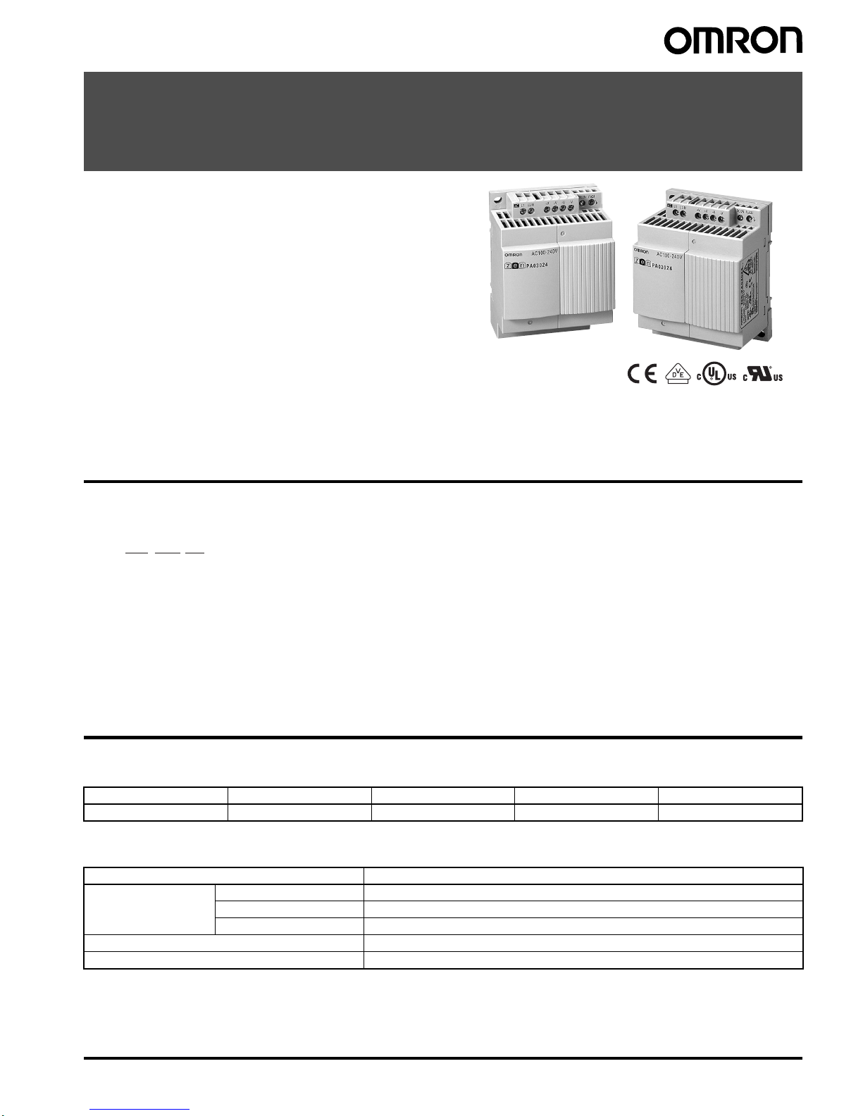
6Switching Mode Power Supply ZEN-PA03024
Safety Precautions
Minor electric shock may occasionally occur. Do not disassemble
the product or touch internal parts.
Minor fires may occasionally occur. Do not attempt to repair or
modify the product.
Minor burns may occasionally occur. Do not touch the product
while power is being supplied or immediately after power is
turned OFF.
Minor fires may occasionally occur. Tighten terminal screws to a
torque of 0.5 to 0.6 N·m so that they do not become loose.
Minor electric shock may occasionally occur during operation. Do
not touch the input and output terminals while power is being
supplied.
The product may occasionally be damaged. Do not allow any
clippings or cuttings to enter the product during installation work.
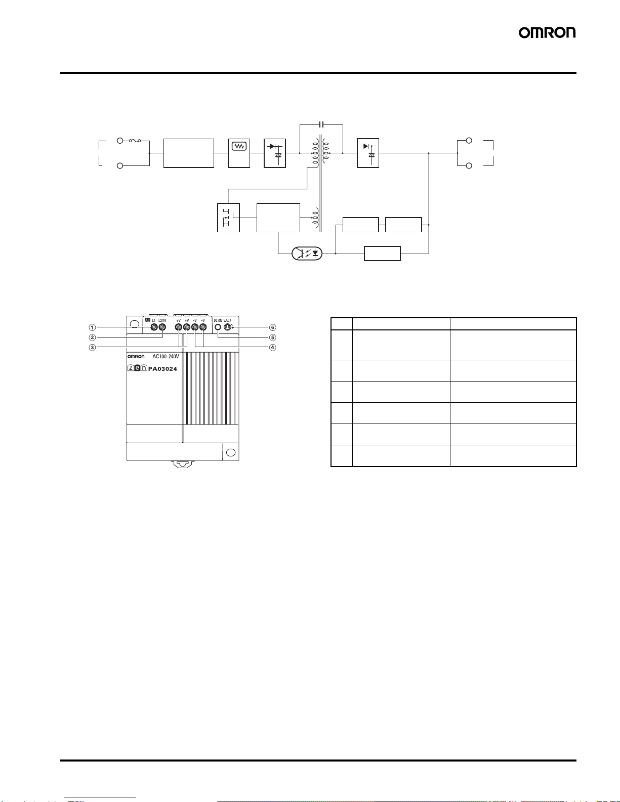
Working voltage can be 350 V max. inside. This voltage can be
also available 10 s after the switch off.
■Precautions for Safe Use
The following precautions must be observed to ensure safety.
Mounting
•Mounting Direction
(Refer to Installation in Engineering Data on page 4.)
The internal parts may occasionally deteriorate or be broken due to
adverse heat dissipation depending on the mounting status. Do not
use the product in any way other than the standard mounting
direction.
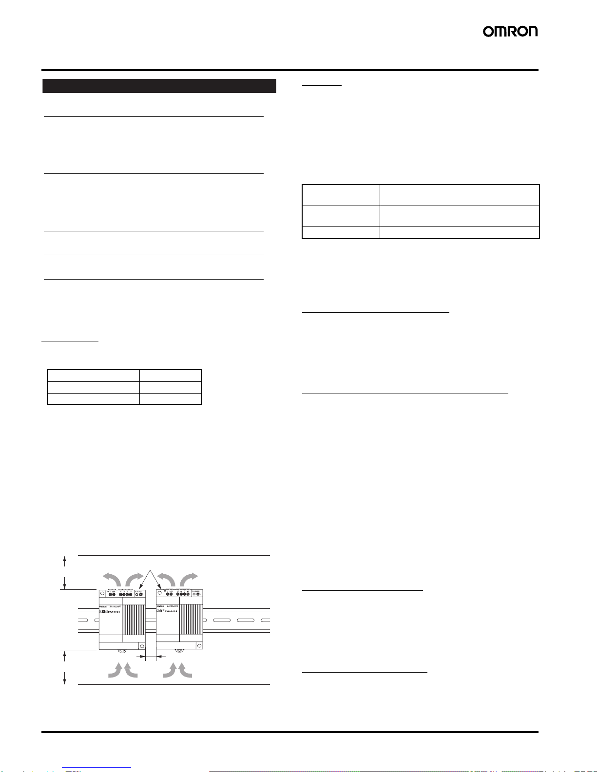
•Mounting Space
Make sure that sufficient heat dissipation is provided when
installing the Power Supply to increase its long-term reliability.
Install the product in a location that allows a natural airflow to occur
around the Power Supply.
We recommend using End Plates (PFP-M) to secure the Power
Supply and to ensure that a space of at least 10 mm is maintained
between Power Supplies.
If the installation space above and below the Power Supply is less
than 50 mm, reduce the ambient temperature by 5°C. A minimum
space of 20 mm is required.
Note: 1. Convection of air
2. 50 mm min.
3. 10 mm min.
Wiring
•Minor fire may possibly occur. Ensure that input and output
terminals are wired correctly.
•Use the following material for the wires to be connected to the
Power Supply to prevent smoking or ignition caused by abnormal
loads.
Use solid wires. Always attach pin crimp terminals when using
stranded wire. The stripping distance should be 6.5 mm.
Recommended Wire Type
•Do not apply more than 100 N force to the terminal block when
tightening the terminals.
•Be sure to remove the sheet covering the product before turning
ON the Power Supply and confirm that nothing is interfering with
heat dissipation.
Installation Environment
•Do not use the Power Supply in locations subject to shocks or
vibrations. In particular, install the Power Supply as far away as
possible from contactors or other devices that are a vibration
source.
•Install the Power Supply well away from any sources of strong,
high-frequency noise.
Operating and Storage Conditions
•When installing the Power Supply, check for any signs that the
product or packaging has been struck. If internal parts have been
damaged, overvoltages may be output depending on the location of
the damage.
•Internal parts may occasionally deteriorate or be damaged. Store
the Power Supply at a temperature of -25 to 65°C and a humidity of
10% to 90%.
•Internal parts may occasionally deteriorate or be damaged. Do not
use the Power Supply in areas outside the derating curve (i.e., the
area shown by shading (1) in the graph on page 4). For UL508
Listing, the surrounding air temperature should be 40°C.
•Use the Power Supply at a humidity of 10% to 90%.
•Do not use the Power Supply in locations where condensation may
occur due to high humidity or where temperature changes are
severe.
•Do not use the Power Supply in locations subject to direct sunlight.
•Do not use the Power Supply in locations where liquids, foreign
matter, or corrosive gases may enter the interior of products.
Overload Protection
•Internal parts may possibly deteriorate or be damaged if a short-
circuited or overcurrent state continues during operation.
•Internal parts may possibly deteriorate or be damaged if the Power
Supply is used for applications with frequent inrush current or
overloading at the load end. Do not use the Power Supply for such
applications.
Charging the Battery
•This product is not intended to function as a battery charger. If a
battery is to be connected as the load, mount an overcurrent
limiting circuit and an overvoltage protection circuit.
Standard Mounting Valid
Horizontal Mounting Invalid
Other Mounting Invalid
!CAUTION
(See note 1.)
(See note 1.)
(See note 2.)
(See note 2.)
ZEN-PA03024
(See note 3.)
Solid wire Cross section 0.5 to 2.5 mm2
(Equivalent to AWG20 to AWG14)
Stranded wire Cross section 0.5 to 2.5 mm2
(Equivalent to AWG20 to AWG14)
Pin crimp terminals Dia.: 1.1 to 2.3 mm