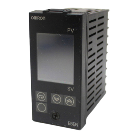
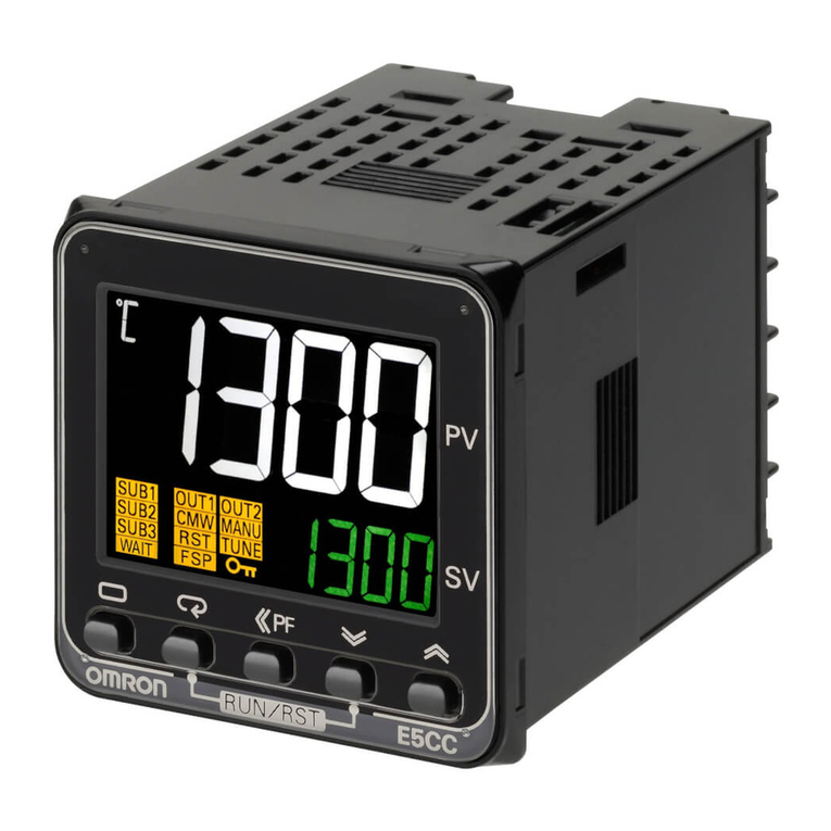
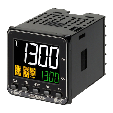
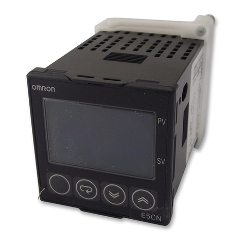
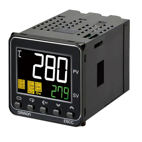
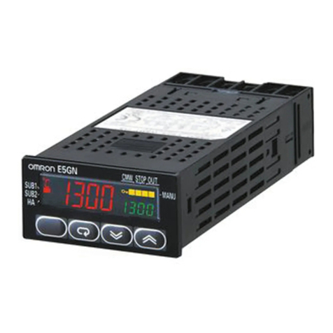
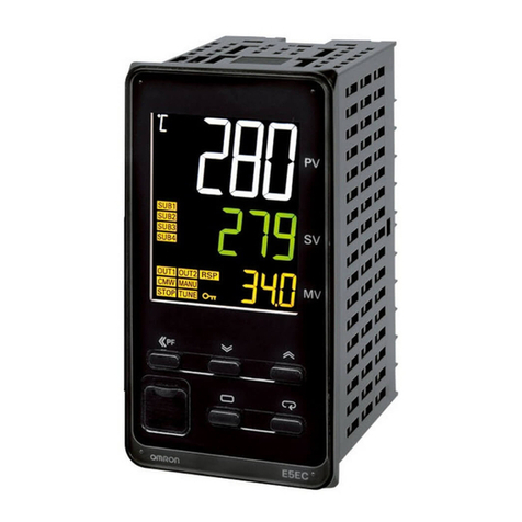
Omron E5 D Series Instruction Manual

Programmable Controller CJ-series
General-purpose Serial
Connection Guide
(RS-485 CompoWay/F)
OMRON Corporation
Digital Temperature Controller
(E5□D/E5□C/E5□C-T)
P704-E1-01

About Intellectual Property Rights and Trademarks
Microsoft product screen shots reprinted with permission from Microsoft Corporation.
Windows is a registered trademark of Microsoft Corporation in the USA and other countries.
Company names and product names in this guide are the trademarks or registered trademarks
of their respective companies.

Table of Contents
1. Related Manuals........................................................................................ 1
2. Terms and Definitions............................................................................... 2
3. Precautions................................................................................................ 3
4. Overview .................................................................................................... 4
5. Applicable Devices and Device Configuration ....................................... 5
5.1. Applicable Devices............................................................................. 5
5.2. Device Configuration.......................................................................... 7
6. Serial Communications Settings ............................................................. 9
6.1. Parameters ........................................................................................ 9
6.2. Cable Wiring .................................................................................... 10
7. Serial Communications Connection Procedure ....................................11
7.1. Work Flow.........................................................................................11
7.2. Digital Temperature Controller Setup............................................... 13
7.3. PLC Setup........................................................................................ 17
7.4. Serial Communication Status Check................................................ 38
8. Initialization Method................................................................................ 44
8.1. Initializing a PLC .............................................................................. 44
8.2. Initializing a Digital Temperature Controller...................................... 45
9. Program.................................................................................................... 46
9.1. Overview.......................................................................................... 46
9.2. Communications Sequence............................................................. 51
9.3. Error Detection Processing.............................................................. 52
9.4. Memory Maps .................................................................................. 53
9.5. Ladder Program............................................................................... 56
9.6. Protocol Data ................................................................................... 62
9.7. Timing Charts................................................................................... 73
9.8. Error Processing .............................................................................. 74
10. Revision History .................................................................................. 77
1
.
Related Manuals
1
1. Related Manuals
To ensure system safety, make sure to always read and follow the information provided in all
Safety Precautions and Precautions for Safe Use in the manuals for each device which is
used in the system.
The table below lists the manuals pertaining to this guide.
Cat. No. Model Manual name
W472 CJ2M-CPU□□
CJ2H-CPU6□
CJ2H-CPU6□-EIP
CJ Series
CJ2 CPU Unit
Hardware USER'S MANUAL
W473 CJ2M-CPU□□
CJ2H-CPU6□
CJ2H-CPU6□-EIP
CJ Series
CJ2 CPU Unit
Software USER'S MANUAL
W336 CJ1W-SCU□1-V1
CJ1W-SCU□2 CJ Series
Serial Communications Units
OPERATION MANUAL
W474 CJ2□-CPU□□ CJ Series
Programmable Controllers
INSTRUCTIONS REFERENCE MANUAL
W446 CXONE-AL□□C-V4
/ AL□□D-V4
CX-Programmer
OPERATION MANUAL
W344 CXONE-AL□□C-V4
/ AL□□D-V4 CX-Protocol
OPERATION MANUAL
H225 E5□D Digital Temperature Controllers
Communications Manual
H224
E5□D
Digital Temperature Controllers User’s Manual
H175 E5□C Digital Temperature Controllers
Communications Manual
H174 E5□C Digital Temperature Controllers User’s Manual
H186 E5□C-T Digital Temperature Controllers
Programmable Type
Communications Manual
H185 E5□C-T Digital Temperature Controllers
Programmable Type User’s Manual

2
.
Terms and Definitions
2
2. Terms and Definitions
Term Explanation and Definition
protocol macro A data transfer procedure (protocol) with a general-purpose external
device is created and stored in a Serial Communications Board or a Serial
Communications Unit. This functional protocol enables data to be
exchanged with general-purpose external devices by executing the
protocol macro instruction (hereinafter referred to as "PMCR instruction")
in a CPU Unit.
protocol A set of rules governing the data transfer procedures that gather
independent communication processing with a specific general-purpose
device. A protocol consists of more than one sequence.
sequence A unit of action to perform the independent communication processing that
can be started by executing the PMCR instruction in a program.
A sequence that is started by the instruction executes steps registered in
its own sequence.
step A unit to execute any one of the followings: message send processing,
message receive processing, message send/receive processing, receive
buffer clear, or step wait. Up to 15 steps can be set for per sequence.
send message A communications frame (command) sent to a general-purpose external
device. A send message is invoked by steps in a sequence and is sent to a
general-purpose external device.
receive message A communications frame (response) sent from a general-purpose external
device. A receive message is invoked by steps in the sequence and is
compared with data received from general-purpose external devices.
matrix A function to register and use some communications frames (responses)
when more than one communications frame is expected to be received
from a general-purpose external device.
The receive processing can be executed according to registered
communications frames by using this function.
case A unit to register multiple communications frames (response) to a matrix.
One communications frame is registered as one case.
Up to 15 types of cases can be registered per matrix.

3
.
Precautions
3
3. Precautions
(1) Understand the specifications of devices which are used in the system. Allow some
margin for ratings and performance. Provide safety measures, such as installing a safety
circuit, in order to ensure safety and minimize the risk of abnormal occurrence.
(2) To ensure system safety, make sure to always read and follow the information provided in
all Safety Precautions and Precautions for Safe Use in the manuals for each device
which is used in the system.
(3) The user is encouraged to confirm the standards and regulations that the system must
conform to.
(4) It is prohibited to copy, to reproduce, and to distribute a part or the whole of this guide
without the permission of OMRON Corporation.
(5) The information contained in this guide is current as of March 2018. It is subject to
change for improvement without notice.
The following notations are used in this guide.
Indicates a potentially hazardous situation which, if not avoided,
may result in minor or moderate injury or property damage.
Precautions for Safe Use
Precautions on what to do and what not to do to ensure safe usage of the product.
Precautions for Correct Use
Precautions on what to do and what not to do to ensure proper operation and performance.
Additional Information
Additional information to read as required.
This information is provided to increase understanding or make operation easier.
Symbol
The triangle symbol indicates precautions (including warnings).
The specific operation is shown in the triangle and explained in the text.
This example indicates a general precaution.
The filled circle symbol indicates operations that you must do.
The specific operation is shown in the circle and explained in the text.
This example shows a general precaution for something that you must do.

4
.
Overview
4
4. Overview
This guide describes procedures for connecting a Digital Temperature Controller (E5□D,
E5□C or E5□C-T) to a CJ-series Programmable Controller + Serial Communications Unit
(hereinafter referred to as the "PLC") via serial communications, both produced by OMRON
Corporation (hereinafter referred to as "OMRON"), and for checking their communication
status.
Refer to Section 6. Serial Communications Settings and Section 7. Serial Communications
Connection Procedure to understand setting methods and key points to send or receive a
message via serial communications.
The ladder program in the prepared CX-Programmer project file is used to check the serial
connection by sending or receiving a message of ''Properties Read'' to/from the Digital
Temperature Controller.
■The send/receive messages of "Properties Read''
PLC
Serial communications
(RS-485)
Digital Temperature
Controller
Sending command data Executing the command
Receiving response data
and storing in memory Returning response data
Prepare the CX-Programmer project file and the CX-Protocol project file with latest versions
beforehand. To obtain the project files, contact your OMRON representative.
Name File name Version
CX-Programmer project file
(extension: cxp) P704_CJ_CWF485_OMRON_E5CD_V100.cxp Ver.1.00
CX-Protocol project file
(extension: psw) P704_CJ_CWF_OMRON_E5CDV100.psw Ver.1.00
This guide aims to explain wiring methods and communications settings
necessary to connect corresponding devices and provides the setting
procedures. The program used in this guide is not designed to be constantly
used at a site but is designed to check if the connection is properly established.
Both functionalities and performances are therefore not fully considered for the
program.
When you actually construct a system, please use the wiring methods,
communications settings and setting procedures described in this guide as a
reference, and design a program according to your application needs.
Command data
Response data

5
.
Applicable Devices and Device Configuration
5
5. Applicable Devices and Device Configuration
5.1. Applicable Devices
The applicable devices are as follows:
Manufacturer Name Model
OMRON
CJ2 CPU Unit
CJ2□-CPU□□
OMRON Serial Communications Unit CJ1W-SCU□1-V1
CJ1W-SCU□2
OMRON Digital Temperature Controller
E5CD-□□2□□M-002
E5CD-□□2□□M-004
E5ED-□□4□□M-004
E5ED-□□4□□M-008
E5ED-□□4□□M-022
E5CC-□□□□□M-002
E5CC-□□□□□M-003
E5CC-□□□□□M-004
E5AC-□□□□SM-004
E5AC-□□□□SM-008
E5AC-□□□□SM-009
E5AC-□□□□SM-012
E5AC-□□□□SM-014
E5EC-□□□□□M-004
E5EC-□□□□□M-008
E5EC-□□□□□M-009
E5EC-□□□□□M-012
E5EC-□□□□□M-014
E5DC-□□□□□M-002
E5DC-□□□□□M-015
E5GC-□□□□□M-015
E5CC-T□□3□SM-002
E5CC-T□□3□SM-003
E5CC-T□□3□SM-004
E5AC-T□□4□SM-004
E5AC-T□□4□SM-008
E5AC-T□□4□SM-020
E5AC-T□□4□SM-022
E5EC-T□□4□SM-004
E5EC-T□□4□SM-008
E5EC-T□□4□SM-020
E5EC-T□□4□SM-022

5
.
Applicable Devices and Device Configuration
6
Precautions for Correct Use
In this guide, the devices with models and versions listed in 5.2. Device Configuration are
used as examples of applicable devices to describe the procedures for connecting the
devices and checking their connection.
You cannot use devices with versions lower than the versions listed in 5.2.
To use the above devices with models not listed in 5.2. or versions higher than those listed in
5.2., check the differences in the specifications by referring to the manuals before operating
the devices.
Additional Information
This guide describes the procedures for establishing the network connection.
It does not provide information on operation, installation, wiring method, device functionality,
or device operation, which is not related to the connection procedures.
Refer to the manuals or contact your OMRON representative.

5
.
Applicable Devices and Device Configuration
7
5.2. Device Configuration
The hardware components to reproduce the connection procedures in this guide are as
follows:
Manufacturer Name Model Version
OMRON
Serial Communications Unit
CJ1W-SCU42
Ver.2.0
OMRON
CJ2 CPU Unit
CJ2M-CPU12
Ver.2.0
OMRON
Power Supply Unit
CJ1W-PA202
OMRON
CX-One
CXONE-AL□□C-V4
/AL□□D-V4
Ver.4.□□
OMRON
CX-Programmer
(Included in CX-One)
Ver.9.65
OMRON
CX-Protocol
(Included in CX-One)
Ver.1.992
OMRON
CX-Programmer project file
P704_CJ_CWF485_
OMRON_E5CD_V100.cxp
Ver.1.00
OMRON
CX-Protocol project file
P704_CJ_CWF_OMRON_
E5CD_V100.psw
Ver.1.00
-
Personal computer (OS: Windows 7)
-
-
USB cable
(USB 2.0 type B connector)
-
-
Serial cable (RS-485)
-
OMRON
Digital Temperature Controller
E5CD-RX2A6M-002
Precautions for Correct Use
Prepare the CX-Programmer project file and the CX-Protocol project file with latest versions
beforehand. To obtain the project files, contact your OMRON representative.
Precautions for Correct Use
Update CX-Programmer and CX-Protocol to the versions specified in this Clause 5.2. or to
higher versions. If you use a version higher than the one specified, the procedures and
related screenshots described in Section 7. and the subsequent sections may not be
applicable. In that case, use the equivalent procedures described in this guide by referring to
the CX-Programmer OPERATION MANUAL (Cat. No. W446) and the CX-Protocol
OPERATION MANUAL (Cat. No. W344).
CJ2M-CPU12
+
CJ1W-SCU42
Personal computer
(CX-One installed,
OS: Windows 7)
USB cable
Serial cable (RS-485)
E5CD-RX2A6M-002

5
.
Applicable Devices and Device Configuration
8
Precautions for Correct Use
Turn ON the terminating resistance switch on Serial Communications Unit and connect
terminating resistance to the terminals of the Digital Temperature Controller at either end of
the RS-422A/485 transmission path.
Additional Information
For information on the serial cable (RS-485), refer to 3-4 RS-232C and RS-422A/485 Wiring
of the CJ Series Serial Communications Units OPERATION MANUAL (Cat. No. W336).
Additional Information
The system configuration in this guide uses USB for the connection between the personal
computer and the PLC. For information on how to install the USB driver, refer to A-5 Installing
the USB Driver of the CJ-series CJ2 CPU Unit Hardware USER'S MANUAL (Cat. No. W472).

6
.
Serial Communications Settings
9
6. Serial Communications Settings
This section describes the parameters and cable wiring, which are set up in this guide.
6.1. Parameters
The following parameters are required to connect the PLC and the Digital Temperature
Controller via serial communications.
Setting item PLC
(Serial Communications Unit)
Digital Temperature
Controller
Unit No. 0 -
Communications Unit No.
(slave address) - 1 (default)
Serial communications port
(connection) Port 1 (RS-422A/485) -
Terminating resistance Terminating resistance ON
(TERM: ON) -
2-wire or 4-wire 2-wire (WIRE: 2) 2-wire (fixed)
Serial communications
mode Protocol macro -
Data length
(transmission character) 7 bits (default) 7 bits (default)
Stop bits 2 bits (default) 2 bits (default)
Parity (parity bit) Even (default) Even (default)
Baud rate 9,600 bps (default) 9,600 bps (default)
Protocol macro transmission
method Half-duplex (default) -
Communications method - CompoWay/F (default)
Send data wait time - 20 ms (default)
Precautions for Correct Use
The connection procedure described in this guide assumes that the following Serial
Communications Unit, port and unit number are used.
Model: CJ1W-SCU42
Serial communications port: Port 1
Unit No.: 0
If you connect devices under different conditions, refer to Section 9. Program and create a
program by changing both the CIO area and the control data of the PMCR instruction.

6
.
Serial Communications Settings
10
6.2. Cable Wiring
For details on cable wiring, refer to SECTION 3 Installation and Wiring of the CJ Series Serial
Communications Units OPERATION MANUAL (Cat. No. W336).
Check the connector configurations and pin assignments before wiring.
■Connector configuration and pin assignment
Serial Communications Unit (CJ1W-SCU42) applicable connector: Terminal block
Pin No.
Symbol
Signal name
Input/Output
1 (See note 1.) RDA Receive data - Input
2 (See note 1.) RDB Receive data + Input
3 (See note 1.) SDA Send data - Output
4 (See note 1.) SDB Send data + Output
5 (See note 2.) FG Shield -
Note 1: For 2-wire connection, use either pins 1 and 2 or pins 3 and 4.
2: Pin 5 (Shield) is connected to the GR terminal on the Power Supply Unit though the
Serial Communications Unit. The cable shield can thus be grounded if you ground
the GR terminal of the Power Supply Unit.
Digital Temperature Controller (E5CD) applicable connector: Terminal block
Pin No.
Signal name
Input/Output
1-12
13
B(+)
Input/Output
14 A(-) Input/Output
15-18
■Cable and pin assignment
Serial Communications
Unit (CJ1W-SCU42) Digital Temperature Controller
(E5CD)
RS-422A/
485
interface
Signal
name Pin No. Terminal
No. Signal
name RS-485
interface
RDA- 1 13 B(+)
RDB+ 2 14 A(-)
SDA- 3
SDB+
4
FG 5
Terminal block Terminal block
*Connect 120 Ω (1/2 W) terminating resistance
between B(+) and A(-) of the Digital Temperature
Controller that is connected at the end of the
network.
Additional Information
For information on the connector configurations and pin assignments of the other models,
refer to their respective manuals.
Terminating resistance

7
.
Serial Communications Connection Procedure
11
7. Serial Communications Connection Procedure
This section describes the procedures for connecting the PLC to the Digital Temperature
Controller via serial communications. The procedures for setting up the PLC and the Digital
Temperature Controller in this guide are based on the factory default settings.
For the initialization, refer to Section 8. Initialization Method.
7.1. Work Flow
Take the following steps to connect the PLC and the Digital Temperature Controller via serial
communications and to send or receive a message.
7.2. Digital Temperature Controller
Setup
Set up the Digital Temperature Controller.
↓
7.2.1. Parameter Settings
Set parameters for the Digital Temperature
Controller.
↓
7.3. PLC Setup
Set up the PLC.
↓
7.3.1. Hardware Settings
Set the hardware switches on the Serial
Communications Unit and connect the cables.
↓
7.3.2. Opening the Project File and
Going Online with the PLC
Start CX-Programmer, open the project file, and go
online with the PLC.
↓
7.3.3. Creating an I/O Table
Create an I/O table for the PLC.
↓
7.3.4. Parameter Settings
Set parameters for the Serial Communications
Unit.
↓
7.3.5. Transferring the Project Data
Transfer the created project data to the PLC.
↓
7.3.6. Starting CX-Protocol and
Opening the Project File
Start CX-Protocol and open the project file.
↓
7.3.7. Going Online and Transferring
the Protocol Data
Go online with CX-Protocol and transfer the
protocol data to the Serial Communications Unit.
↓

7
.
Serial Communications Connection Procedure
12
7.4. Serial Communication Status
Check
Start the send/receive processing and confirm that
serial communications performs normally.
↓
7.4.1. Starting the Trace Start tracing with CX-Protocol.
↓
7.4.2. Executing the Communications
Sequence Execute the communications sequence with
CX-Programmer.
↓
7.4.3. Checking the Trace Data Check that correct data is sent and received, using
the trace data in CX-Protocol.
↓
7.4.4. Checking Received Data With CX-Programmer, check that correct data is
written to the I/O memory of the PLC.

7
.
Serial Communications Connection Procedure
13
7.2. Digital Temperature Controller Setup
Set up the Digital Temperature Controller.
Parameter Settings7.2.1.
Set parameters for the Digital Temperature Controller.
1
Connect the power supply and a
serial cable to the terminal block
located on the back of Digital
Temperature Controller.
*Only the parameters in
Communications Setting Level
are described in this guide.
If you use the parameters in
Adjustment Level that is
specific to each of the models,
refer to their respective
manuals.
2
Check the positions of each of
the keys, No.1 and No. 2
displays and Operation
indicators.
In this guide, the keys are
described as follows:
L (Level) Key
M (Mode) Key
U (Up) Key
D
(Down) Key
3
Turn ON Digital Temperature
Controller.
4
The current temperature is
displayed on No. 1 display once
Digital Temperature Controller is
turned ON. (Operation Level)
Press the L(Level) Key for at
least 3 seconds.
L(Level) Key for at least 3 seconds
Serial cable
(RS-485)

7
.
Serial Communications Connection Procedure
14
5
"in-t" (Initial Setting Level) is
displayed on No. 1 display.
Press the L(Level) Key again
for less than 1 second.
L(Level) Key
6
The display changes to
Communications Setting Level.
"psel" (Protocol Setting) and
"cwf" (CompoWay/F) are
displayed on No. 1 and No. 2
displays, respectively.
*If the setting value is different,
press the U(Up) or D(Down)
Key to change the parameter.
Press the M(Mode) Key.
< Setting value>
CWF / Mod
(default: CWF)
CWF: CompoWay/F
Mod: Modbus-RTU
M(Mode) Key
7
"u-no" (Communications Unit
No.) is displayed.
Check that Communications
Unit No. is 1.
*If the setting value is different,
change it in the same way as
step 6.
Press the M(Mode) Key.
<Setting value>
0 to 99 (default: 1)
M(Mode) Key
8
"bps" (Communications Baud
Rate) is displayed.
Check that Communications
Baud Rate is 9.6 kbps.
*If the setting value is different,
change it in the same way as
step 6.
Press the M(Mode) Key.
<Setting value>
9.6, 19.2, 38.4 or
57.6 kbps
(default: 9.6)
M(Mode) Key

7
.
Serial Communications Connection Procedure
15
9
"len" (Communications Data
Length) is displayed.
Check that Communications
Data Length is 7 bits.
*If the setting value is different,
change it in the same way as
step 6.
Press the M(Mode) Key.
<Setting value>
7 or 8 bits (default: 7)
M(Mode) Key
10
"sbit" (Communications Stop
Bits) is displayed.
Check that Communications
Stop Bits is 2 bits.
*If the setting value is different,
change it in the same way as
step 6.
Press the M(Mode) Key.
<Setting value>
1 or 2 bits (default: 2)
M(Mode) Key
11
"prty" (Communications Parity)
is displayed.
Check that Communications
Parity is EVEN.
*If the setting value is different,
change it in the same way as
step 6.
Press the M(Mode) Key.
<Setting value>
NONE, EVEN or ODD
(default: EVEN)
M(Mode) Key
12
"sdwt" (Send Data Wait Time) is
displayed.
Check that Send Data Wait Time
is 20.
*If the setting value is different,
change it in the same way as
step 6.
Press the L(Level) Key for less
than 1 second.
<Setting value>
0 to 99 ms (default: 20)
L(Level) Key

7
.
Serial Communications Connection Procedure
16
13
"in-t" ((Initial Setting Level) is
displayed.
Press the L(Level) Key for at
least 1 second.
L(Level) Key for at least 1 second
14
The display returns to Operation
Level as shown in step 4.
15
Turn OFF Digital Temperature
Controller.

7
.
Serial Communications Connection Procedure
17
7.3. PLC Setup
Set up the PLC.
Hardware Settings7.3.1.
Set the hardware switches on the Serial Communications Unit and connect the cables.
Precautions for Correct Use
Make sure that the power supply is OFF when you set up.
If it is ON, the settings described in the following steps and subsequent procedures may not
be applicable.
1
Make sure that PLC is powered
OFF.
2
Check the positions of the
hardware switches and Port 1
on the front panel of Serial
Communications Unit by
referring to the figure on the
right.
3
Set Unit number switch to 0.
The unit number is set to 0 as
the factory default setting.
4
Set Terminating resistance
ON/OFF switch to ON.
(Terminating resistance ON).
5
Set 2-wire or 4-wire switch to 2
(2-wire).
・TERM
(Terminating resistance ON/OFF switch)
OFF: Terminating resistance OFF
ON: Terminating resistance ON
・WIRE (:2-wire or 4-wire switch)
2: 2-wire, 4: 4-wire
Other manuals for E5 D Series
1
This manual suits for next models
2
Table of contents
Other Omron Temperature Controllers manuals

Omron
Omron E5CN User manual

Omron
Omron E5C series User manual

Omron
Omron E5EC User manual

Omron
Omron E5CC-B-800 User manual

Omron
Omron EJ1 EtherCAT User manual

Omron
Omron E5EC User manual

Omron
Omron E5 J Series User manual

Omron
Omron E5EWL User manual

Omron
Omron E5AN User manual

Omron
Omron E5AX-P Series User manual

Omron
Omron E5CN-H User manual

Omron
Omron E5C2 User manual

Omron
Omron E5ZN-SCT User manual

Omron
Omron E5ZE User manual

Omron
Omron E5ZN Series User manual

Omron
Omron E5DC User manual

Omron
Omron E5CC Use and care manual

Omron
Omron E5GN-QTD User manual

Omron
Omron E5ZN-DRT User manual

Omron
Omron E5C series User manual