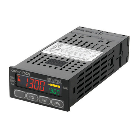
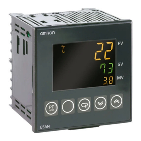
Omron E5GN User manual

Cat.No. H101–E1–2
Temperature Controller
E5GN
USER’S MANUAL

E5GN
I
The E5GN compact temperature controller features the following:
•The E5GN can be mounted on compact panels
•The user can select from thermocouple, platinum resistance thermometer, nonĆconĆ
tact temperature sensor and analog voltage inputs.
•The user can select AT autoĆtuning) and ST selfĆtuning) as tuning functions.
•The user can use the communications function when the communications function
is supported).
•The user can calibrate sensor input.
•The E5GN features a watertight construction NEMA4X: equivalent to IP66).
•The E5GN conforms to UL/CSA/IEC safety standards and EMC standards.
This User's Manual describes how to use the E5GN.
Before using your E5GN, thoroughly read and understand this manual in order to
ensure correct use.
Also, store this manual in a safe place so that it can be retrieved whenever necessary.
* For an additional description of the communications function, also refer to the
E5AN/EN/CN/GN Temperature Controller, Communications Function User's
Manuals Cat. No. H102)
EOMRON, 1998
All rights reserved. No part of this publication may be reproduced, stored in a retrieval system or transmitted,
in any form, or by any means, mechanical, electronic, photocopying, recording, or otherwise, without the prior
written permission of OMRON.
No patent liability is assumed with respect to the use of the information contained herein. Moreover, because
OMRON is constantly striving to improve its high-quality products, the information contained in this manual is
subject to change without notice. Every precaution has been taken in the preparation of this manual. Neverthe-
less, OMRON assumes no responsibility for errors or omissions. Neither is any liability assumed for damages
resulting from the use of the information contained in this publication.
Preface

E5GN
II
PRECAUTIONS
When the product is used under the circumstances or environment described in this
manual always adhere to the limitations of the rating and functions. Also, for safety,
take countermeasures such as fitting fail safe installations.
DO NOT USE :
•In circumstances or environments that have not been described below in this manual.
•For control in nuclear power, railway, aircraft, vehicle, incinerator, medical, entertainment,
or safety applications.
•Where death or serious property damage may occur, or where extensive safety precautions
are required.

E5GN
III
SAFETY PRECAUTIONS
JSafety Signal Words
This manual uses the following signal words to mark safety precautions for the E5GN.
These precautions provide important information for the safe application of the product. You
must be sure to follow the instructions provided in all safety precautions.
WARNING Indicates information that, if not heeded, could possibly result in loss of life or
serious injury.
CAUTION Indicates information that, if not heeded, could result in relatively serious or
minor injury, damage to the product, or faulty operation.
JSafety Precautions
CAUTION
FElectric Shock Warning
Do not touch the terminals while the power is ON.
Doing so may cause an electric shock.
Do not allow metal fragments or lead wire scraps to fall inside this product.
These may cause electric shock, fire or malfunction.
Never disassemble, repair or modify the product.
Doing so may cause electric shock, fire or malfunction.
Do not use the product in flammable and explosive gas atmospheres.
The life expectancy of the output relays varies greatly with the switching capacity and other switching
conditions. Always use the output relays within their rated load and electrical life expectancy. If an outĆ
put relay is used beyond its life expectancy, its contacts may become fused or burned.
Use the product within the rated load.
Not doing so may cause damage or burning.
Use this product within the rated supply voltage.
Not doing so may cause damage or burning.
Tighten the terminal screws properly. Tighten them to a torque of 0.24 Nm 2.5kgfcm) max on termiĆ
nals 1 to 6. Tighten them to a torque of 0.13 Nm 1.4kgfcm) max on terminals 7 to 9.
Loose screws may cause malfunction.
Set all settings according to the control target of the product.
If the settings are not appropriate for the control target, the product may operate in an unexpected manĆ
ner, resulting in damage to the product or resulting in accidents.
To maintain safety in the event of a product malfunction, always take appropriate safety measures, such
as installing an alarm on a separate line to prevent excessive temperature rise.
If a malfunction prevents proper control, a major accident may result.

E5GN
IV
NOTICE
Be sure to observe these precautions to ensure safe use.
1) Do not wire unused terminals.
2) Be sure to wire properly with correct polarity of terminals.
3) To reduce induction noise, separate the highĆvoltage or largeĆcurrent power lines from other lines,
and avoid parallel or common wiring with the power lines when you are wiring to the terminals.
We recommend using separating pipes, ducts, or shielded lines.
4) Do not use this product in the following places:
•Places subject to dust or corrosive gases in particular, sulfide gas and ammonia gas)
•Places subject to high humidity, condensation or freezing
•Places subject to direct sunlight
•Places subject to vibration and large shocks
•Places subject to splashing liquid or oily atmosphere
•Places directly subject to heat radiated from heating equipment
•Places subject to intense temperature changes
5) To allow heat to escape, do not block the area around the product. Ensure that enough space is
left for the heat to escape.) Do not block the ventilation holes on the casing.
6) When you have removed the terminal plate, never touch electric components inside or subject the
internal mechanism to shock.
7) Cleaning: Do not use paint thinner or the equivalent. Use standard grade alcohol to clean the prodĆ
uct.
8) Use AWG24 to AWG14 leads for terminal Nos.1 to 6 and AWG28 to AWG22 leads for terminal
Nos.7 to 9 with lead cover peel back allowance of 5 or 6 mm).
9) Allow as much space as possible between the E5GN and devices that generate powerful highĆfreĆ
quency noise e.g. highĆfrequency welders, highĆfrequency sewing machines) or surges.
10) When executing selfĆtuning, turn the load e.g. heater) ON simultaneously or before you turn the
E5GN ON. If you turn the E5GN ON before turning the load ON, correct selfĆtuning results and
optimum control may no longer be obtained.
11) Use a 100 to 240 VAC 50/60 Hz), 24 VAC 50/60 Hz) or 24 VDC power supply matched to the power
specifications of the E5GN. Also, make sure that the rated voltage is attained within two seconds
of turning the power ON.
12) Attach a surge suppresser or noise filter to peripheral devices that generate noise in particular,
motors, transformers, solenoids, magnetic coils or other equipment that have an inductance comĆ
ponent).
13) When mounting a noise filter on the power supply, be sure to first check the filter's voltage and
current capacity, and then mount the filter as close as possible to the E5GN.
14) Use within the following temperature and humidity ranges:
•Temperature: Ć10 to 55_C, Humidity: 25 to 85% with no icing or condensation)
If the E5GN is installed inside a control board, the ambient temperature must be kept to under
55_C, including the temperature around the E5GN.
If the E5GN is subjected to heat radiation, use a fan to cool the surface of the E5GN to under 55_C.
15) Store within the following temperature and humidity ranges:
•Temperature: Ć25 to 65_C, Humidity: 25 to 85% with no icing or condensation)
16) Never place heavy objects on, or apply pressure to the E5GN as it may cause it to deform and deteriĆ
orate during use or storage.
17) Avoid using the E5GN in places near a radio, television set, or wireless installation. These devices
can cause radio disturbances which adversely affect the performance of the E5GN.
E5GN
V
JMeanings of Abbreviations
The following abbreviations are used in parameter names, figures and in text explanations.
These abbreviations mean the following:
Symbol Term
PV Process value
SP Set point
AT AutoĆtuning
ST SelfĆtuning
EU Engineering unit *1
*1 EU" stands for Engineering Unit. EU is used as the minimum unit for engineering units
such as _C, m, and g.
The size of EU varies according to the input type. For example, when the input temperature
setting range is -200 to +1300_C, 1 EU is 1_C, and when the input temperature setting range
is -20.0 to +500.0_C, 1 EU is 0.1_C.
In the case of analog input, the size of EU varies according to the decimal point position of
the scaling setting, and 1 EU becomes the minimum scaling unit.
JHow to Read Display Symbols
The following tables show the correspondence between the symbols displayed on the displays
and alphabet characters.
ABCDEFGHI JKLM
NOPQRSTUVWXYZ
J“Reference” mark
This mark indicates that extra, useful information follows, such as supplementary explanations
and how to apply functions.
Conventions Used in This Manual

E5GN
VI
JHow This Manual is Organized
Purpose Related title Description
FLearning about the
E5GN
Chapter 1 INTRODUCTION This chapter describes the
features, names of parts and
typical functions.
FSetting up Chapter 2 PREPARATIONS This chapter describes
installation and wiring.
FBasic operations Chapter 3 BASIC OPERATION and
Chapter 5 PARAMETERS
These chapters describe
basic control examples.
FApplied operations Chapter 4 APPLIED OPERATION and
Chapter 5 PARAMETERS
These chapters describe
advanced functions to fully
use the E5GN.
FCalibration Chapter 6 CALIBRATION This chapter describes calĆ
ibration method.

E5GN
Preface I. . . . . . . . . . . . . . . . . . . . . . . . . . . . . . . . . . . . .
Precautions II. . . . . . . . . . . . . . . . . . . . . . . . . . . . . . . . .
Safety Precautions III. . . . . . . . . . . . . . . . . . . . . . . . . . .
Notice IV. . . . . . . . . . . . . . . . . . . . . . . . . . . . . . . . . . . . . .
Conventions Used in This Manual V. . . . . . . . . . . . . .
CHAPTER 1 INTRODUCTION 1-1. . . . . . . . . . . . . . . . . . . . . . . . . . .
1.1 Names of Parts 1-2. . . . . . . . . . . . . . . . . . . . . . . . . . . . . . . . . . . . . . . . . .
Front panel 1-2. . . . . . . . . . . . . . . . . . . . . . . . . . . . . . . . . . . . . . . . . . . . . . . . . . . . . . . . .
Display 1-2. . . . . . . . . . . . . . . . . . . . . . . . . . . . . . . . . . . . . . . . . . . . . . . . . . . . . . . . . . . .
How to use keys 1-3. . . . . . . . . . . . . . . . . . . . . . . . . . . . . . . . . . . . . . . . . . . . . . . . . . . .
1.2 I/O Configuration and Main Functions 1-4. . . . . . . . . . . . . . . . . . . . . .
I/O configuration 1-4. . . . . . . . . . . . . . . . . . . . . . . . . . . . . . . . . . . . . . . . . . . . . . . . . . . .
Main functions 1-5. . . . . . . . . . . . . . . . . . . . . . . . . . . . . . . . . . . . . . . . . . . . . . . . . . . . . .
1.3 How Setup Levels Are Configured and Operating
the Keys on the Front Panel 1-6. . . . . . . . . . . . . . . . . . . . . . . . . . . . . . .
Selecting parameters 1-8. . . . . . . . . . . . . . . . . . . . . . . . . . . . . . . . . . . . . . . . . . . . . . . .
Fixing settings 1-8. . . . . . . . . . . . . . . . . . . . . . . . . . . . . . . . . . . . . . . . . . . . . . . . . . . . . .
1.4 Communications Function 1-9. . . . . . . . . . . . . . . . . . . . . . . . . . . . . . . .
CHAPTER 2 PREPARATIONS 2-1. . . . . . . . . . . . . . . . . . . . . . . . . . .
2.1 Installation 2-2. . . . . . . . . . . . . . . . . . . . . . . . . . . . . . . . . . . . . . . . . . . . . .
Dimensions 2-2. . . . . . . . . . . . . . . . . . . . . . . . . . . . . . . . . . . . . . . . . . . . . . . . . . . . . . . .
Panel cutout 2-2. . . . . . . . . . . . . . . . . . . . . . . . . . . . . . . . . . . . . . . . . . . . . . . . . . . . . . . .
Mounting 2-3. . . . . . . . . . . . . . . . . . . . . . . . . . . . . . . . . . . . . . . . . . . . . . . . . . . . . . . . . . .
Removing and attaching the terminal plate 2-3. . . . . . . . . . . . . . . . . . . . . . . . . . . . . .
2.2 Wiring Terminals 2-4. . . . . . . . . . . . . . . . . . . . . . . . . . . . . . . . . . . . . . . . .
Terminal arrangement 2-4. . . . . . . . . . . . . . . . . . . . . . . . . . . . . . . . . . . . . . . . . . . . . . .
Precautions when wiring 2-4. . . . . . . . . . . . . . . . . . . . . . . . . . . . . . . . . . . . . . . . . . . . .
Wiring 2-4. . . . . . . . . . . . . . . . . . . . . . . . . . . . . . . . . . . . . . . . . . . . . . . . . . . . . . . . . . . . .
2.3 Requests at Installation 2-7. . . . . . . . . . . . . . . . . . . . . . . . . . . . . . . . . . .
To ensure prolonged use 2-7. . . . . . . . . . . . . . . . . . . . . . . . . . . . . . . . . . . . . . . . . . . . .
To reduce the influence of noise 2-7. . . . . . . . . . . . . . . . . . . . . . . . . . . . . . . . . . . . . . .
To ensure high–precision measurement 2-7. . . . . . . . . . . . . . . . . . . . . . . . . . . . . . . .
About waterproofing 2-8. . . . . . . . . . . . . . . . . . . . . . . . . . . . . . . . . . . . . . . . . . . . . . . . .
CHAPTER 3 BASIC OPERATION 3-1. . . . . . . . . . . . . . . . . . . . . . . .
3.1 Initial Setup Examples 3-2. . . . . . . . . . . . . . . . . . . . . . . . . . . . . . . . . . . .
3.2 Setting the Input Type 3-4. . . . . . . . . . . . . . . . . . . . . . . . . . . . . . . . . . . .
Input type 3-4. . . . . . . . . . . . . . . . . . . . . . . . . . . . . . . . . . . . . . . . . . . . . . . . . . . . . . . . . .
3.3 Selecting _C/_F 3-5. . . . . . . . . . . . . . . . . . . . . . . . . . . . . . . . . . . . . . . . .
Temperature unit 3-5. . . . . . . . . . . . . . . . . . . . . . . . . . . . . . . . . . . . . . . . . . . . . . . . . . . .
3.4 Selecting PID Control or ON/OFF Control 3-6. . . . . . . . . . . . . . . . . . .
3.5 Setting Output Specifications 3-7. . . . . . . . . . . . . . . . . . . . . . . . . . . . . .
Control period 3-7. . . . . . . . . . . . . . . . . . . . . . . . . . . . . . . . . . . . . . . . . . . . . . . . . . . . . .
Direct/reverse operation 3-7. . . . . . . . . . . . . . . . . . . . . . . . . . . . . . . . . . . . . . . . . . . . . .
Table of Contents

E5GN
3.6 Setting the SP 3-9. . . . . . . . . . . . . . . . . . . . . . . . . . . . . . . . . . . . . . . . . . .
Changing the SP 3-9. . . . . . . . . . . . . . . . . . . . . . . . . . . . . . . . . . . . . . . . . . . . . . . . . . . .
3.7 Executing ON/OFF Control 3-10. . . . . . . . . . . . . . . . . . . . . . . . . . . . . . . .
ON/OFF control 3-10. . . . . . . . . . . . . . . . . . . . . . . . . . . . . . . . . . . . . . . . . . . . . . . . . . . . .
Setup 3-11. . . . . . . . . . . . . . . . . . . . . . . . . . . . . . . . . . . . . . . . . . . . . . . . . . . . . . . . . . . . . .
3.8 Determining PID Constants (AT, ST, manual setup) 3-12. . . . . . . . . . .
AT (auto-tuning) 3-12. . . . . . . . . . . . . . . . . . . . . . . . . . . . . . . . . . . . . . . . . . . . . . . . . . . . .
ST (self-tuning) 3-13. . . . . . . . . . . . . . . . . . . . . . . . . . . . . . . . . . . . . . . . . . . . . . . . . . . . .
ST start conditions 3-14. . . . . . . . . . . . . . . . . . . . . . . . . . . . . . . . . . . . . . . . . . . . . . . . . .
ST stable range 3-14. . . . . . . . . . . . . . . . . . . . . . . . . . . . . . . . . . . . . . . . . . . . . . . . . . . . .
Manual setup 3-15. . . . . . . . . . . . . . . . . . . . . . . . . . . . . . . . . . . . . . . . . . . . . . . . . . . . . . .
3.9 Alarm Output 3-17. . . . . . . . . . . . . . . . . . . . . . . . . . . . . . . . . . . . . . . . . . . .
Alarm type 3-18. . . . . . . . . . . . . . . . . . . . . . . . . . . . . . . . . . . . . . . . . . . . . . . . . . . . . . . . .
Alarm value 3-19. . . . . . . . . . . . . . . . . . . . . . . . . . . . . . . . . . . . . . . . . . . . . . . . . . . . . . . .
3.10 Requests during Operation 3-20. . . . . . . . . . . . . . . . . . . . . . . . . . . . . . . .
CHAPTER 4 APPLIED OPERATION 4-1. . . . . . . . . . . . . . . . . . . . . .
4.1 Shifting Input Values 4-2. . . . . . . . . . . . . . . . . . . . . . . . . . . . . . . . . . . . .
Shifting input 4-2. . . . . . . . . . . . . . . . . . . . . . . . . . . . . . . . . . . . . . . . . . . . . . . . . . . . . . .
How to calculate input shift values (2-point shift) 4-3. . . . . . . . . . . . . . . . . . . . . . . . .
4.2 Alarm Hysteresis 4-6. . . . . . . . . . . . . . . . . . . . . . . . . . . . . . . . . . . . . . . .
Standby sequence 4-6. . . . . . . . . . . . . . . . . . . . . . . . . . . . . . . . . . . . . . . . . . . . . . . . . .
Alarm latch 4-6. . . . . . . . . . . . . . . . . . . . . . . . . . . . . . . . . . . . . . . . . . . . . . . . . . . . . . . . .
Close in alarm/open in alarm 4-7. . . . . . . . . . . . . . . . . . . . . . . . . . . . . . . . . . . . . . . . . .
4.3 Setting Scaling Upper and Lower Limits (analog input) 4-8. . . . . . . .
Analog input 4-8. . . . . . . . . . . . . . . . . . . . . . . . . . . . . . . . . . . . . . . . . . . . . . . . . . . . . . . .
4.4 Executing Heating and Cooling Control 4-9. . . . . . . . . . . . . . . . . . . . .
Heating and cooling control 4-9. . . . . . . . . . . . . . . . . . . . . . . . . . . . . . . . . . . . . . . . . . .
Setup 4-10. . . . . . . . . . . . . . . . . . . . . . . . . . . . . . . . . . . . . . . . . . . . . . . . . . . . . . . . . . . . . .
4.5 Setting Multi-SP 4-11. . . . . . . . . . . . . . . . . . . . . . . . . . . . . . . . . . . . . . . . .
Setting the SP by key operation 4-11. . . . . . . . . . . . . . . . . . . . . . . . . . . . . . . . . . . . . . .
Setup 4-11. . . . . . . . . . . . . . . . . . . . . . . . . . . . . . . . . . . . . . . . . . . . . . . . . . . . . . . . . . . . . .
4.6 Setting the SP Upper and Lower Limit Values 4-13. . . . . . . . . . . . . . .
Set point limitter 4-13. . . . . . . . . . . . . . . . . . . . . . . . . . . . . . . . . . . . . . . . . . . . . . . . . . . .
Setup 4-14. . . . . . . . . . . . . . . . . . . . . . . . . . . . . . . . . . . . . . . . . . . . . . . . . . . . . . . . . . . . . .
4.7 Executing the SP Ramp Function
(limiting the SP change rate) 4-15. . . . . . . . . . . . . . . . . . . . . . . . . . . . . .
SP ramp 4-15. . . . . . . . . . . . . . . . . . . . . . . . . . . . . . . . . . . . . . . . . . . . . . . . . . . . . . . . . . .
4.8 To Move to the Advanced Function Setting Level 4-17. . . . . . . . . . . .
4.9 Using the Key Protect level 4-18. . . . . . . . . . . . . . . . . . . . . . . . . . . . . . .
Key protect 4-18. . . . . . . . . . . . . . . . . . . . . . . . . . . . . . . . . . . . . . . . . . . . . . . . . . . . . . . . .
CHAPTER 5 PARAMETERS 5-1. . . . . . . . . . . . . . . . . . . . . . . . . . . . .
Conventions Used in this Chapter 5-2. . . . . . . . . . . . . . . . . . . . . . . . . . . . . .
Protect Level 5-3. . . . . . . . . . . . . . . . . . . . . . . . . . . . . . . . . . . . . . . . . . . . . . . . .
Operation Level 5-4. . . . . . . . . . . . . . . . . . . . . . . . . . . . . . . . . . . . . . . . . . . . . .
Adjustment Level 5-10. . . . . . . . . . . . . . . . . . . . . . . . . . . . . . . . . . . . . . . . . . . . .
Initial Setting Level 5-17. . . . . . . . . . . . . . . . . . . . . . . . . . . . . . . . . . . . . . . . . . .

E5GN
Advanced Function Setting Level 5-25. . . . . . . . . . . . . . . . . . . . . . . . . . . . . . .
Communications Setting Level 5-36. . . . . . . . . . . . . . . . . . . . . . . . . . . . . . . . .
CHAPTER 6 CALIBRATION 6-1. . . . . . . . . . . . . . . . . . . . . . . . . . . . .
6.1 Parameter Structure 6-2. . . . . . . . . . . . . . . . . . . . . . . . . . . . . . . . . . . . .
6.2 User Calibration 6-3. . . . . . . . . . . . . . . . . . . . . . . . . . . . . . . . . . . . . . . . .
6.3 Calibrating Thermocouples 6-4. . . . . . . . . . . . . . . . . . . . . . . . . . . . . . . .
6.4 Calibrating Analog Input 6-7. . . . . . . . . . . . . . . . . . . . . . . . . . . . . . . . . .
6.5 Calibrating Platinum Resistance Thermometers 6-8. . . . . . . . . . . . .
6.6 Checking Indication Accuracy 6-9. . . . . . . . . . . . . . . . . . . . . . . . . . . . .
APPENDIX A-1. . . . . . . . . . . . . . . . . . . . . . . . . . . . . . . . . . . . . . . . . . . . .
SPECIFICATIONS A-2. . . . . . . . . . . . . . . . . . . . . . . . . . . . . . . . . . . . . . . . . . . .
Ratings A-2. . . . . . . . . . . . . . . . . . . . . . . . . . . . . . . . . . . . . . . . . . . . . . . . . . . . . . . . . . . .
Characteristics A-3. . . . . . . . . . . . . . . . . . . . . . . . . . . . . . . . . . . . . . . . . . . . . . . . . . . . . .
ERROR DISPLAY A-4. . . . . . . . . . . . . . . . . . . . . . . . . . . . . . . . . . . . . . . . . . . .
PARAMETER OPERATIONS LIST A-6. . . . . . . . . . . . . . . . . . . . . . . . . . . . . .
SENSOR INPUT SETTING RANGES A-9. . . . . . . . . . . . . . . . . . . . . . . . . . .
SETUP LEVELS DIAGRAM A-10. . . . . . . . . . . . . . . . . . . . . . . . . . . . . . . . . . . .
PARAMETER FLOW A-11. . . . . . . . . . . . . . . . . . . . . . . . . . . . . . . . . . . . . . . . . .

CHAPTER 1 INTRODUCTION
1–1
CHAPTER 1
INTRODUCTION
CHAPTER1
1.1 Names of Parts 1Ć2. . . . . . . . . . . . . . . . . . . . . . . .
Front panel 1Ć2. . . . . . . . . . . . . . . . . . . . . . . . . . .
Display 1Ć2. . . . . . . . . . . . . . . . . . . . . . . . . . . . . . .
How to use keys 1Ć3. . . . . . . . . . . . . . . . . . . . . . .
1.2 I/O Configuration and Main Functions 1Ć4. . .
I/O configuration 1Ć4. . . . . . . . . . . . . . . . . . . . . . .
Main functions 1Ć5. . . . . . . . . . . . . . . . . . . . . . . .
1.3 How Setup Levels Are Configured and
Operating the Keys on the Front Panel 1Ć6. . .
Selecting parameters 1Ć8. . . . . . . . . . . . . . . . . . .
Fixing settings 1Ć8. . . . . . . . . . . . . . . . . . . . . . . . .
1.4 Communications Function 1Ć9. . . . . . . . . . . . . .

CHAPTER 1 INTRODUCTION
E5GN
1–2
1.1 Names of Parts
JFront panel
CMW STP OUT
Temperature unit No.1 display
Level key
Operation
indicators
No.2 display
Up key
Mode key Down key
JDisplay
Displays the process value or parameter type.
Displays the set point, manipulated variable or set value setup) of the
parameter.
1) AL alarm)
Lights when alarm output is ON.
2) CMW communications writing control)
Lights when communications writing is enabled" and is out when it
is disabled."
3) STP stop)
Lights when control of the E5GN has been stopped.
During control, this indicator lights when the run/stop function has
been stopped.
4) OUT control output 1, control output 2)
Lights when control output 1, or control output 2 is ON.
The temperature unit is displayed when the display unit parameter is set
to a temperature. Indication is determined by the currently selected temĆ
perature unit" parameter set value. When this parameter is set to _C",
" is displayed, and when set to _F", " is displayed.
FNo.1 display
FNo.2 display
FOperation
indicators
FTemperature unit

1.1Names of Parts
E5GN
1–3
The following describes the basic functions of the front panel keys.
Press this key to select the setting levels. The setting level is selected in
order operation level" ↔ adjustment level" and initial setting level" ↔
communications setting level".
Press this key to select parameters within each level.
Each press of this key increments values displayed on the No.2 display.
Holding down this key continuously increments values.
Each press of this key decrements values displayed on the No.2 display.
Holding down this key continuously decrements values.
This key combination sets the E5GN to the protect mode". For details on
the protect level, see Chapter 5 parameters.
JHow to use keys
F(level) key
F(mode) key
F(up) key
F(down) key
F+ key
combination

CHAPTER 1 INTRODUCTION
E5GN
1–4
1.2 I/O Configuration and Main Functions
JI/O configuration
Controller
Controloutput 1
Control output 2 Heating and cooling
Standard
Alarm 1
Input error
Alarmoutput 1
OUT1
OUT2
Temperature input/
analog input
Communications
function
Controloutput 1
ALM1

1.2I/O Configuration and Main Functions
E5GN
1–5
The following introduces the main functions of the E5GN. For details on
each function and how to use the functions, see Chapter 3 onwards.
ÕThe following input sensors can be connected for temperature input:
Thermocouple : K, J, T, E, L, U, N, R, S, B
NonĆcontact temperature sensor ES1A
: K 10 to 70_C), K 60 to 120_C), K 115 to 165_C),
ĂĂK160 to 260_C
Platinum resistance thermometer
: JPt100, Pt100
Analog input : 0 to 50 mV
ÕControl output is either relay or voltage output depending on the model
of E5GN.
Ă•Alarms are supported on the E5GNĆj1jj. Set the alarm type and
alarm value, or upperĆ and lowerĆlimit alarms.
ÕIf necessary, a more comprehensive alarm function can be achieved by
setting the standby sequence", alarm hysteresis" and close in alarm/
open in alarm" parameters.
Ă•Optimum PID constants can be set easily by AT autoĆtuning) and ST
selfĆtuning).
ÕCommunications according to *CompoWay/F are supported on the
E5GNĆj03j.
Communications are carried out over the RSĆ485 interface.
* CompoWay/F is a generalĆpurpose serial communicationsĆbased unified
communications procedure developed by OMRON. CompoWay/F uses
commands compliant with the wellĆestablished FINS, together with a uniĆ
fied frame format on OMRON programmable controllers to facilitate
communications between personal computers and components.
JMain functions
FInput sensor
types
FControl output
FAlarms
FControl
adjustment
FCommunications
function

CHAPTER 1 INTRODUCTION
E5GN
1–6
1.3 How Setup Levels Are Configured and Operating
the Keys on the Front Panel
Parameters are divided into groups, each called a level". Each of the set
values setup items) in these levels is called a parameter." The parameĆ
ters on the E5GN are divided into the following seven levels:
When the E5GN is turned ON, all items in the display light for about one
second.
Password input
set value “1201”
Advanced
function setting level
Calibration level
Password input
set value “-169”
Control stops.
Initial setting level
Less than
1 second
key
key
Commu-
nications
setting level
The PV flashes after one second.
Power ON
Operation level
1 second min.
+ key
Protect level
Control in progress
Control stopped
Adjustment level
key 3 seconds min.
Less than
1 second
key
1 second min.
key
1 second min.
key
Note :
Communicationssetting level is displayed
only when E5GN-V03Vwith communica-
tions function is used.
3 seconds min.
+ key
The PV display
flashes .
+ key
Control in
Progress Control Stopped
Protect level f-
Operation level f-
Adjustment level f-
Initial setting level -f
Advanced function setting level -f
Calibration level -f
Communications setting level -f
f : Indicates items that can be set.
Of these levels, the initial setting level, communications setting level,
advanced function setting level and calibration level can be used only
when control has stopped. Note that the controller outputs are stopped
when these four levels are selected.

1.3How Setup Levels Are Configured and Operating the Keys on the Front Panel
E5GN
1–7
ÕTo move the mode at this level, simultaneously press the and
keys for at least three seconds in the operation level or adjustment level.
This level is for preventing unwanted or accidental modification of
parameters. Protected levels will not be displayed, and so the parameĆ
ters in that level cannot be modified.
Ă* The key pressing time can be changed in protect level move time".
ÕThis level is displayed when you turn the power ON. You can move to the
protect level, initial setting level and adjustment level from this level.
Ă•Normally, select this level during operation. During operation, the proĆ
cess value, set point and manipulated variable can be monitored, and the
alarm value and upperĆ and lowerĆlimit alarms can be monitored and
modified.
ÕTo move the mode at this level, press the key for less than one
second.
ÕThis level is for entering set values and offset values for control. This
level contains parameters for setting the AT autoĆtuning), communicaĆ
tions writing enable/disable, hysteresis, multiĆSP, input shift values and
PID constants. You can move to the top parameter of the initial setting
level and operation level from here.
ÕTo move the mode at this level, press the key for at least three seconds
in the operation level or adjustment level or adjustment level. The PV disĆ
play flashes after one second.
ÕThis level is for specifying the input type, selecting the control method,
control period, setting direct/reverse action and alarm type. When you
move to the operation level from the initial setting level, all items in the
display light.)
ÕYou can move to the advanced function setting level or communications
setting level from this level. To return to the operation level, press the
key for at least one second. To move to the communication setting
level, press the key for less than one second.
Ă•To move the mode at this level, you must enter the password Ć169") in
the initial setting level.
ÕYou can move to the calibration level only from this level.
Ă•This level is for setting the automatic return of display mode, MV limitĆ
ter, standby sequence, alarm hysteresis, ST selfĆtuning) and for moving
to the user calibration level.
ÕTo move the mode at this level, press the key for less than one second
in the initial setting level.
ÕWhen the communications function is used, set the communications
conditions in this level. Communicating with a personal computer host
computer) allows set points to be read and written, and manipulated
variables to be monitored.
NOTE This level is available only on the E5GNĆV03V .
FProtect level
FOperation level
FAdjustment level
FInitial setting
level
FAdvanced
function setting
level
FCommunications
setup level

CHAPTER 1 INTRODUCTION
E5GN
1–8
ÕTo move the mode at this level, you must enter the password 1201" in
the advanced function setting level. This level is for offsetting deviation
in the characteristics on the input circuit.
ÕYou cannot move to other levels by operating the keys on the front panel
from the calibration level. To cancel this level, turn the power OFF then
back ON again.
ÕTo select parameters in each level, press the key. Each press of the
key advances to the next parameter. For details on each parameter,
see Chapter 5.
Parameter
1
Parameter
2
Parameter
3
Paramete
n
ÕIf you press the key at the final parameter, the display returns to the
top parameter for the current level.
ÕTo change parameter settings or setup, specify the setting using the
or keys, and either leave the setting for at least two seconds or press
the key. This fixes the setting.
ÕWhen another level is selected, the parameter and setting on the display
are fixed.
Ă•When you turn the power OFF, you must first fix the settings or parameĆ
ter setup by pressing the key or selecting another mode). The setĆ
tings and parameter setup are sometimes not changed by merely pressĆ
ing the or keys.
FCalibration level
JSelecting
parameters
JFixing settings

1.4Communications Function
E5GN
1–9
1.4 Communications Function
The E5GN can be provided with a communications function that allows
you to check and set controller parameters on a host computer. If the comĆ
munications function is required, use the model supporting the commuĆ
nications function E5GNĆj03j. For details on the communications funcĆ
tion, see the separate Communications Functions User's Manual."
Follow the procedure below to move to the communication setting level.
1) Press the key for at least three seconds in the operation level".
The level moves to the initial setting level".
2) Press the key for less than one second. The initial setting level"
moves to the communications setting level".
3) Pressing the key advances the parameters as shown in the followĆ
ing figure.
4) Press the or keys to change the parameter setups.
Communications unit No.
Baud rate
Data bit
Stop bit
Parity
Set the E5GN communications specifications so that they match the comĆ
munications setup of the host computer. In the case of a oneĆtoĆN connecĆ
tion, match the communications setup of all units.
Parameter Symbol Setting Set value Default Unit
Communications unit No. 0 to 99 1 None
Baud rate 1.2, 2.4, 4.8, 9.6, 19.2 .... .,,,, 9.6 kbps
Data bit 7, 8 7 Bit
Stop bit 1, 2 2 Bit
Parity None, even, odd ,, Even None
FSetting up
communications
data

CHAPTER 1 INTRODUCTION
E5GN
1–10
Other manuals for E5GN
7
Table of contents
Other Omron Temperature Controllers manuals

Omron
Omron E5CN User manual

Omron
Omron E5GC-6 Series User manual

Omron
Omron E5ZE User manual

Omron
Omron E5CC User manual

Omron
Omron E5EX-H User manual

Omron
Omron E5CC-B-800 User manual

Omron
Omron E5CS-X - User manual

Omron
Omron E5CS-U User manual

Omron
Omron E5CN-HR2M-500 User manual

Omron
Omron E5CD-B-800 Series User manual