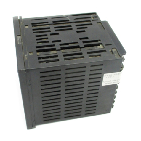
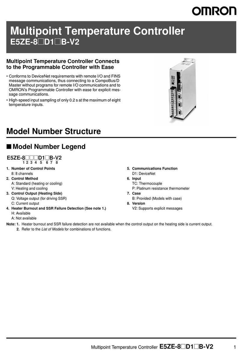
Omron E5AF User manual

E5AF/E5EF
Fuzzy Temperature Controller
Operation Manual
Produced July 1992


Notice:
OMRON products are manufactured for use according to proper procedures by a qualified operator
and only for the purposes described in this manual.
The following conventions are used to indicate and classify warnings in this manual. Always heed the
information provided with them.
Indicates information that, if not heeded, could result in loss of life or serious
injury.
Indicates information that, if not heeded, could result in minor injury or dam-
age to the product.
OMRON Product References
All OMRON products are capitalized in this manual. The word “Unit” is also capitalized when it refers
to an OMRON product, regardless of whether or not it appears in the proper name of the product.
The abbreviation “PC” means Programmable Controller and is not used as an abbreviation for any-
thing else.
Visual Aids
The following headings appear in the left column of the manual to help you locate different types of
information.
Indicates information of particular interest for efficient and convenient opera-
tion of the product.
Indicates lists of one sort or another, such as procedures, precautions, etc.
OMRON, 1992
!
DANGER!
Caution
Note
1, 2, 3...


!
"# $ %!&%'&%'( )
!
" #!!$ % &
'$ (! )
* + * *&, !
, -
. *
/ 0 ,
& # 1 # 2
) 3 0 /
3 /
&
!
* . 3 )
,
#
/ # ! *
& 4 - *
- ,
)
-5! /
'
* ) '
* *
* " % #!! **
* (!6 '$ **
** ! 7 **
*, 1 *,
* 8 *&
*/ -,##)6 #!! -5! 9 *
*& -,##)6 #!! -5! 9 ,&
+ ) ,-
, (! &
, " %8 % (
++ -
# # /
" (! # /
. -
) // -0
12 (

.
About this Manual:
The manual describes the operation of the E5AF/E5EF Fuzzy Temperature Controller and includes
the sections described below.
Please read this manual completely and be sure you understand the information provided before at-
tempting to operate the Fuzzy Temperature Controller.
Section 1
introduces the basic features of the E5AF/E5EF Fuzzy Temperature Controller’s front pan-
el and a brief description of its remote mode and local mode.
Section 2
gives a general description of the E5AF/E5EF Fuzzy Temperature Controller’s rear panel
communications connector/terminals.
Section 3
provides the interface specifications and basic operational elements required in order to
use the RS-232C/RS-422/RS-485 Controllers and also provides the header codes.
Section 4
provides the basic operational elements required in order to use the BCD Output Models
and also gives two examples of its use.
Section 5
describes the connections and settings of the Transmission Output Models.
Appendix A
provides an ASCII list.
Appendix B
provides a list of optional accessories.

8 2 : ! 8 -,#-,- ;;$ ! < !

1--1 Front Panel
The following diagram identifies the major features found on the Fuzzy Tem-
perature Controller front panel and gives a brief description of the function of
each front panel feature.
E5AF-A
=
Remote Key
Press this key for at least 1 s to
enable remote operation. Press
again to enable local operation
and setting via key operation.
This key cannot be used on the
Transmission Output Model.
Display Key
Press this key to shift the
display to the next
parameter.
Front Cover
Down Key
Press this key to decrease the value on the
display. Hold down the key to successively
decrease the value on the display.
Auto-tuning (AT) indicator
Flashes during auto-tuning
Shift indicator
Lights when input
shift function is used.
Remote indicator
Lights when in remote
mode; OFF when in local
mode.
Output (OUT) indicator
Lights when control output is
ON; OFF with current output.
Level Key
Press this key for at least 2 s to
change display levels.
Up Key
Press this key to increase
the value on the display.
Hold down the key to
successively decrease the
value on the display.
Auto-tuning (AT) Key
Press for at least 1 s to begin auto-
tuning. Press again for at least 1 s to
stop auto-tuning.
Process Value (PV) display
Displays process value, characters identifying
the parameter being set, and error messages.
Set Value (SV) display
Displays main settng and other
values.
Alarm Output 1 (ALM1) indicator
Lights when Alarm Output 1 is ON.
Alarm Output 2 (ALM2) indicator
Lights when Alarm Output 2 is ON.
1--2 Remote Mode and Local Mode
Remote mode Pressing the Remote Key puts the E5AF/E5EF in remote mode. In remote
mode, the keys on the front panel of the E5AF/E5EF cannot be used, except
for monitoring the set value with the Display Key, Level Key, and Remote
Key.
Local mode Pressing the Remote Key again puts the E5AF/E5EF in local mode and en-
ables settings via keys on the front panel. In the local mode, the E5AF/E5EF
cannot be remotely controlled, except for reading of the process temperature.
The changing from one mode to the other cannot be remotely controlled.
Section 1--2

!
The Heater Burnout Detection Models are shown below.
E5AF-AH E5EF-AH
Section 1--2

8 2 ! 8 -,#-,- ! 1!
! 8 >? 2 $! : %8 8 -,#-,- ;;$
!

,
2--1 Connector/Terminals
Depending upon the requirements, one of several connector/terminals can
be used.
Communications connector
A 25-pin D-sub Connector for connecting to
the host computer when communications
are executed using RS-232C or BCD.
E5AF-
01 (RS-232C)
E5AF-
20 (BCD)
Communications connector
A 9-pin D-sub Connector for connecting to the host
computer when communications are executed using
RS422, RS485 or transmission output.
E5AF-
02 (RS-422)
E5AF-
03 (RS-485)
E5AF-
F (transmission output)
Communications terminal (5P)
E5AF-
02-X (RS-422)
E5AF-
03-X (RS-485) E5AF-
F-X
(transmission output)
Communications terminal (2P)
Terminal Connections
E5EF-A
4to20mA
9
8
+
-- 12 VDC 40 mA
+
--
9
8
9
8
7
6
5
4
3
2
1
17
16
15
14
13
12
11
10
11
10 +
-- 11
10
B
A
12 B
100 to 240 VAC
50/60 Hz
FG
Use these terminals
when connecting a
thermocouple.
Use these terminals when
connecting a platinum re-
sistance thermometer.
SP SHIFT
Alarm output 2
Alarm output 1
Control
output
9
8Ground FG terminal 17 to avoid noise interference.
For relay or
SSR output
For voltage
output
For current
output
Note: Do not connect unused terminals.
Section 2--1

-
E5EF-AH (with Heater Burnout Alarm)
Note: *The Current Transformer must be the E54-CT1 or
E54-CT3. Other Current Transformer cannot be con-
nected.
**The heater burnout alarm goes ON when the E5EF
detects a sensor failure or heater burnout.
12 VDC 40 mA
+
--
9
8
9
8
7
6
5
4
3
2
1
17
16
15
14
13
12
11
10
11
10 +
-- 11
10
B
A
12 B
100 to 240 VAC
50/60 Hz
FG
SP SHIFT
Heater burnout alarm output**
9
8Ground FG terminal 17 to avoid noise interference.
For voltage
output
CT
Current Transformer (CT)*
For relay or
SSR output
Alarm output
Control
output
Use these terminals
when connecting a
thermocouple.
Use these terminals when
connecting a platinum resis-
tance thermometer.
E5EF-BA (with 8 Memory Banks)
4to20mA
9
8
+
-- 12 VDC 40 mA
+
--
9
8
9
8
7
6
5
4
3
2
1
17
16
15
14
13
12
11
10
11
10 +
-- 11
10
B
A
12 B
100 to 240 VAC
50/60 Hz
FG
Use these terminals
when connecting a
thermocouple.
Use these terminals when
connecting a platinum re-
sistance thermometer.
BANK2
BANK1
BANK0
Alarm output 2
Alarm output 1
Control
output
9
8Ground FG terminal 17 to avoid noise interference.
For relay or
SSR output
For voltage
output
For current
output
Note: Do not connect unused terminals.
E5EF-BAH (with 8 Memory Banks and Heater Burnout Alarm)
Note: *The Current Transformer must be the E54-CT1 or
E54-CT3. Other Current Transformer cannot be con-
nected.
**The heater burnout alarm goes ON when the E5EF
detects a sensor failure or heater burnout.
12 VDC 40 mA
+
--
9
8
9
8
7
6
5
4
3
2
1
17
16
15
14
13
12
11
10
11
10 +
-- 11
10
B
A
12 B
100 to 240 VAC
50/60 Hz
FG
BANK2
BANK1
BANK0
Heater burnout alarm output**
9
8Ground FG terminal 17 to avoid noise interference.
For voltage
output
CT
Current Transformer (CT)*
For relay or
SSR output
Alarm output
Control
output
Use these terminals
when connecting a
thermocouple.
Use these terminals when
connecting a platinum resis-
tance thermometer.
Section 2--1

(
E5EF-A02 (with RS-422 Communications)
4to20mA
9
8
+
-- 12 VDC 40 mA
+
--
9
8
9
8
7
6
5
4
3
2
1
17
16
15
14
13
12
11
10
11
10 +
-- 11
10
B
A
12 B
100 to 240 VAC
50/60 Hz
FG
SDA
RDB
RDA
9
8Ground FG terminal 17 to avoid noise interference.
For relay or
SSR output
For voltage
output
For current
output
SG
SDB
Use these terminals
when connecting a
thermocouple.
Use these terminals when
connecting a platinum re-
sistance thermometer.
Alarm output 2
Alarm output 1
Control
output
Note: Do not connect unused terminals.
E5EF-AH02 (with RS-422 Communications and Heater Burnout Alarm)
12 VDC 40 mA
+
--
9
8
9
8
7
6
5
4
3
2
1
17
16
15
14
13
12
11
10
11
10 +
-- 11
10
B
A
12 B
100 to 240 VAC
50/60 Hz
FG
SDA
RDB
RDA
9
8Ground FG terminal 17 to avoid noise interference.
SG
SDB
CT
Heater burnout alarm output**
For voltage
output unit
Current Transformer (CT)*
For relay or
SSR output
Alarm output
Control
output
Use these terminals
when connecting a
thermocouple.
Use these terminals when
connecting a platinum resis-
tance thermometer.
Note: *The Current Transformer must be the E54-CT1 or
E54-CT3. Other Current Transformer cannot be con-
nected.
**The heater burnout alarm goes ON when the E5EF
detects a sensor failure or heater burnout.
E5EF-A03 (with RS-485 Communications)
4to20mA
9
8
+
-- 12 VDC 40 mA
+
--
9
8
9
8
7
6
5
4
3
2
1
17
16
15
14
13
12
11
10
11
10 +
-- 11
10
B
A
12 B
100 to 240 VAC
50/60 Hz
FG
B
A
9
8Ground FG terminal 17 to avoid noise interference.
SG
SDB
Use these terminals
when connecting a
thermocouple.
Use these terminals when
connecting a platinum resis-
tance thermometer.
Alarm output 2
Alarm output 1
Control
output
For relay or
SSR output
For voltage
output
For current
output
Note: Do not connect unused terminals.
Section 2--1

0
E5EF-AH03 (with RS-485 and Heater Burnout Alarm)
12 VDC 40 mA
+
--
9
8
9
8
7
6
5
4
3
2
1
17
16
15
14
13
12
11
10
11
10 +
-- 11
10
B
A
12 B
100 to 240 VAC
50/60 Hz
FG
B
A
9
8Ground FG terminal 17 to avoid noise interference.
SG
CT
Heater burnout alarm output**
For voltage
output
Current Transformer (CT)*
For relay or
SSR output
Alarm output
Control
output
Use these terminals
when connecting a
thermocouple.
Use these terminals when
connecting a platinum resis-
tance thermometer.
Note: *The Current Transformer must be the E54-CT1 or
E54-CT3. Other Current Transformer cannot be con-
nected.
**The heater burnout alarm goes ON when the E5EF
detects a sensor failure or heater burnout.
2--2 Connecting Communications Connectors/Terminals
Connect a host system or peripheral device to the appropriate communica-
tions connector; confirm that the system or device conforms to that connec-
tor’s communications specifications. Before mounting the Fuzzy Temperature
Controller, be sure to consider the added depth required by connected
cables.
Panel
*1
*2
Depth of the main body from panel when mounted
*1: Without OMRON XM4
D-sub Connector *2: With OMRON XM4 D-sub Connector
100 mm No less than 170 mm (25-pin connector)
No less than 160 mm (9-pin connector)
The following OMRON D-sub Connectors are recommended:
25 pin: XM4A-2521 (plug) + XM2S-2511 (hood)
9 pin: XM4A-0921 (plug) + XM2S-0911 (hood)
If using an equivalent connector, make sure that the connector screws are
the following metric size: M2.6 x 0.45 mm.
Section 2--2

3
Securely insert the communications connector from the external system into
the communications connector on the Temperature Controller. After connec-
tion, tighten the screws on either side of the communications connector with
a screwdriver.
When connecting communications via terminal blocks, use crimp-style termi-
nals of the appropriate size for use with M3 x 8 mm connector screws.
65.8 max.
For the appropriate cable length, refer to the respective communications
specifications.
Section 2--2

!
"# $ %!&%'&%'(
8 !2 8 ! : > 8
* *&, 8 8 !2 8 :8
! ! 5!
!
*
*&,
" #!!$ % &
'$ (! )
* + * *&, !
, -
,
, "@
, -
,*
. *
/ 0 ,
& # 1 # 2
) 3 0 /
3 /
&
!
* . 3 )
,
#
/ # ! *
& 4 - *
- ,
)
-5! /
-5! * *&, /
(! -5! *)

3--1 Interface Specifications
3--1--1 RS-232C This interface is for the E5AF only. Electrical characteristics conform to EIA
RS-232C.
Communications Signals
14
1
13
25
Signal Abbreviation Signal
direction Pin no.
Frame ground (safety ground) FG ------ 1
Signal ground or common return SG ------ 7
Send data SD Output 2
Receive data RD Input 3
Request to send RS Output 4
Clear to send CS Input 5
Data set ready DR Input 6
Data terminal ready ER Output 20
Connection Diagram
The following diagram shows how the E5AF is connected to the host comput-
er using the RS-232C.
If the terminals are connected as shown by the
dotted lines in the figure, which is not absolutely
necessary, the cable can be used regardless of
the direction.
SD
FG
DR
CS
SD
RD
RS
ER
FG
SG
CS
RD
RS
DR
SG
1
2
3
4
5
20
7
6
1
2
3
4
5
20
7
6
LT1081CN or equivalent
Host computer
RS-232C E5AF
RS-232C
Pin
no.
Shielded cable
TX
RX
+V
Abbrevi-
ation Pin
no. Abbrevi-
ation
ER
Section 3--1

!
Synchronization: Internal clock
Cable length: 15 m maximum. To increase the cable length, use
OMRON’s RS-232C optical interface (Z3RN).
Applicable connectors: Plug: XM4A-2521 (OMRON) or equivalent
Hood: XM2S-2511 (OMRON) or equivalent
Connection method (RS-232C direct connection): 1:1 connection only
A carrier detect (CD) signal for the host computer is not supported by the
E5AF via its RS-232C port since the E5AF’s RS-232C is defined as DTE
(Data Terminal Equipment). If a CD signal is needed, it must be provided a
the host computer.
3--1--2 RS-422 Electrical characteristics conform to EIA RS-422.
Communications Signals
The following information identifies the input/output signals of the interface.
24
23
22
21
20
Terminals
69
1
5
Connector
Signal Abbreviation Signal direction Connector pin no. Terminal no.
Send Data A SDA Output 921
Send Data B SDB Output 520
Receive Data A RDA Input 623
Receive Data B RDB Input 124
Signal Ground SG ------ 322
Frame Ground (safety ground) FG ------ 7------
Section 3--1

'
Connection Diagram
The following illustration shows how the E5AF is connected to the host com-
puter via RS-422.
RS-422
Host computer
Abbre-
viation
Termination
resistance
The termination re-
sistance must have
a minimum resis-
tance of 100
.
FG
RDA
RDB
SDA
SDB
SG
9
5
6
1
3
Abbre-
viation
Pin
no.
SDA
SDB
RDA
RDB
SG
Shielded cable
E5AF
RS-422
220
220
6.8 V
MC34050 or equivalent
The termination resistance (220
) can be connected closing by SW601 and SW602.
SW601
SW602
Synchronization: Internal clock
Cable length: 500 m maximum (total)
Applicable connectors: Plug: XM2A-0901 (OMRON) or equivalent
XM4A-0921 (OMRON) or equivalent
Hood: XM2S-0911 (OMRON) or equivalent
Connection method (RS-422 connection): Maximum 1:32 connection
Note SW601 and SW602 of the terminator must be turned on. SW601 and SW602
of the Controllers other than the terminator must be turned off.
Section 3--1
This manual suits for next models
1
Table of contents
Other Omron Temperature Controllers manuals

Omron
Omron E5GN User manual

Omron
Omron E5CC-B-800 User manual

Omron
Omron E5EX-P User manual

Omron
Omron E5CC User manual

Omron
Omron E5CN User manual

Omron
Omron E5GN User manual

Omron
Omron E5ZE-8 E Series User manual

Omron
Omron E5CC-T User manual

Omron
Omron E5 J Series User manual

Omron
Omron E5 D Series Instruction Manual

Omron
Omron E5 N H - Parts list manual

Omron
Omron E5CN-FR User manual

Omron
Omron E5AN User manual

Omron
Omron EJ1G User manual

Omron
Omron E5CN-H User manual

Omron
Omron E5ZN Series User manual

Omron
Omron E5ZE User manual

Omron
Omron ES1B User manual

Omron
Omron E5 D Series Use and care manual

Omron
Omron E5EN User manual