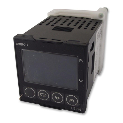
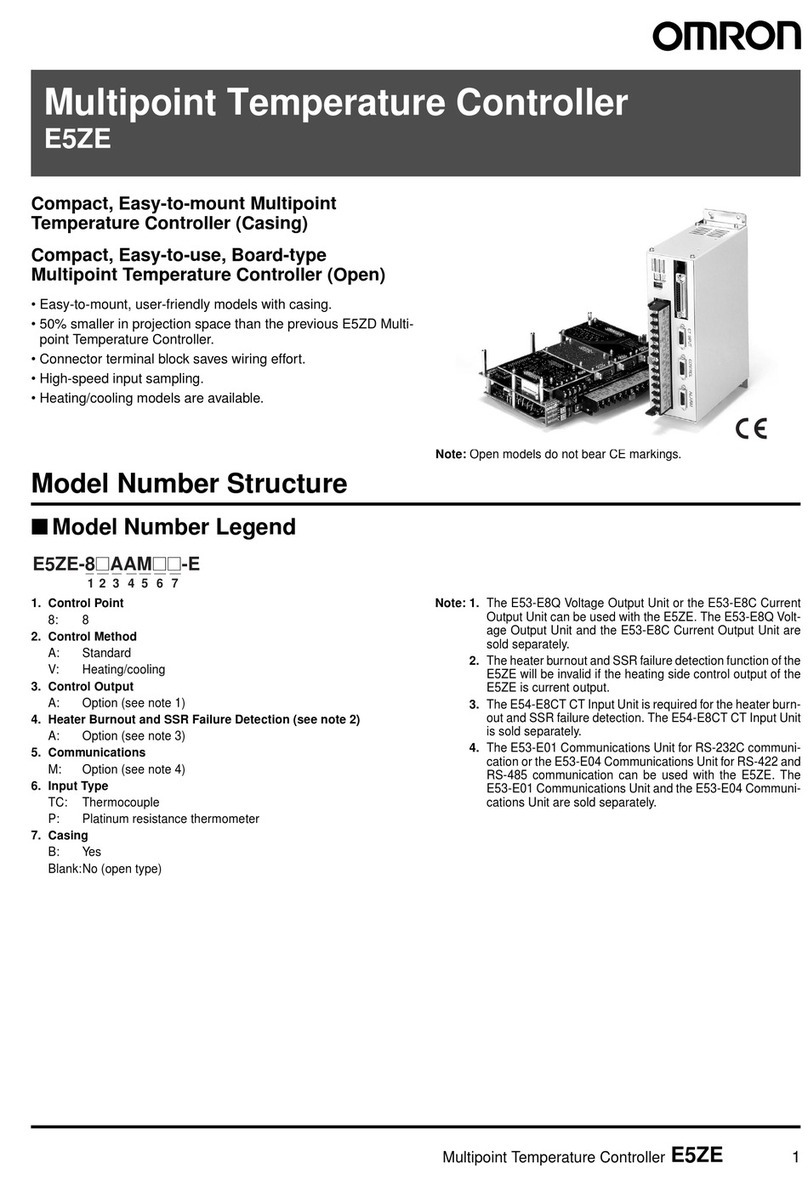
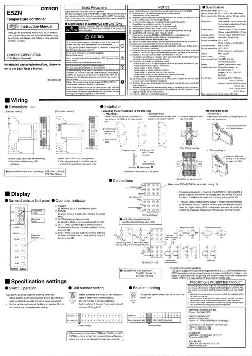
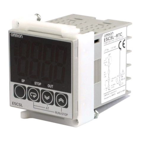
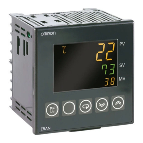
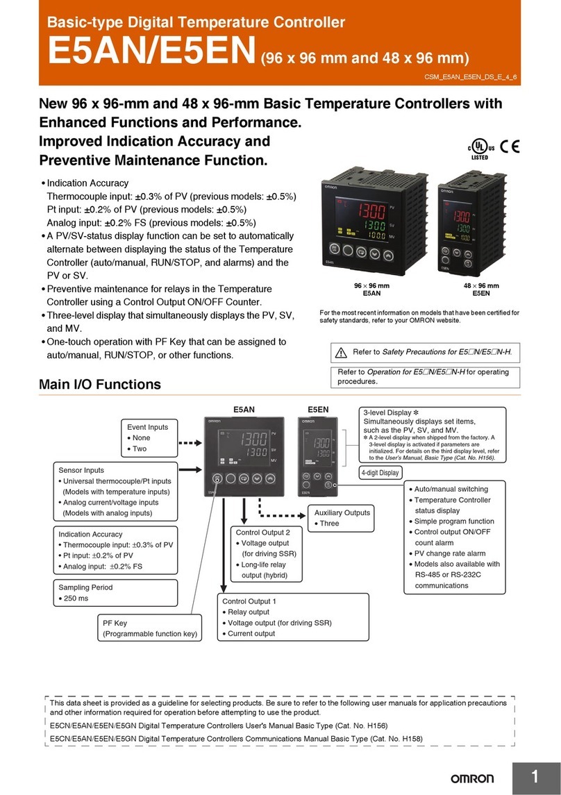
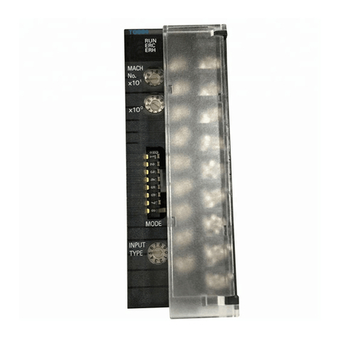
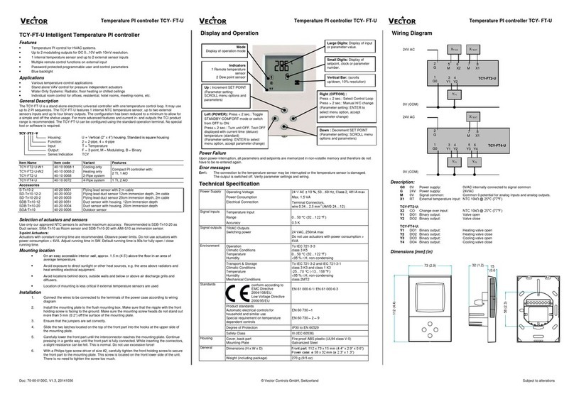
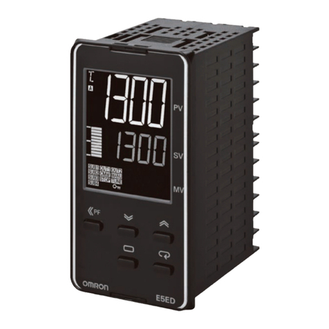
Omron E5EN User manual

USER MANUAL
Cat.No. H111-E1-2
E5EN
Temperature Controller

I
The temper ture controller E5EN llows the user to c rry out the following:
•
Select from m ny types of temper ture, nonĆcont ct temper ture sensor nd n log
input
•
Select he ting nd cooling control in ddition to st nd rd control
•
Select AT ( utoĆtuning) nd ST (selfĆtuning) s tuning functions
•
Use multiĆSP nd the run/stop function ccording to event input (for units equipped
with the event input function)
•
Use the HBA (he ter burnout l rm) function (for units equipped with the he ter
burnout l rm function)
•
Use the communic tions function (for units equipped with the communic tions
function)
•
C libr te sensor input
•
The E5EN fe tures w tertight construction (NEMA4X : equiv lent to IP66).
•
The E5EN conforms to UL/CSA/IEC s fety st nd rds nd EMC st nd rds.
* This User's M nu l describes how to use the E5EN.
Before using your E5EN, thoroughly re d nd underst nd this m nu l in order to
ensure correct use.
Also, store this m nu l in s fe pl ce so th t it c n be retrieved whenever necess ry.
* For n ddition l description of the communic tions function, lso refer to the
E5AN/EN/CN/GN Temper ture Controller, Communic tions Function User's
M nu ls (C t. No. H102).
E
OMRON, 1999
All rights reser ed. No part of this publication may be reproduced, stored in a retrie al system or transmitted,
in any form, or by any means, mechanical, electronic, photocopying, recording, or otherwise, without the prior
written permission of OMRON.
No patent liability is assumed with respect to the use of the information contained herein. Moreo er, because
OMRON is constantly stri ing to impro e its highĆquality products, the information contained in this manual is
subject to change without notice. E ery precaution has been taken in the preparation of this manual. Ne ertheĆ
less, OMRON assumes no responsibility for errors or omissions. Neither is any liability assumed for damages
resulting from the use of the information contained in this publication.
Preface

II
PRECAUTIONS
When the product is used under the circumstances or environment described in this
manual, always adhere to the limitations of the rating and functions. Also, for safety,
take countermeasures such as fitting fail safe installations.
DO NOT USE :
•
In circumstances or environments that have not been described below in this manual.
•
For control in nuclear power, railway, aircraft, vehicle, incinerator, medical, entertainment,
or safety applications.
•
Where death or serious property damage may occur, or where extensive safety precautions
are required.

III
SAFETY PRECAUTIONS
J
Safety Signal Words
This anual uses the following signal words to ark safety precautions for the E5EN.
These precautions provide i portant infor ation for the safe application of the product. You
ust be sure to follow the instructions provided in all safety precautions.
WARNING
Indicates infor ation that, if not heeded, could possibly result in loss of life or
serious injury.
CAUTION
Indicates infor ation that, if not heeded, could result in relatively serious or
inor injury, da age to the product, or faulty operation.
J
Safety Preca tions
CAUTION
F
Electric Shock Warning
Do not touch the ter inals while the power is ON.
Doing so ay cause an electric shock.
Do not allow etal frag ents or lead wire scraps to fall inside this product.
These ay cause electric shock, fire or alfunction.
Never disasse ble, repair or odify the product.
Doing so ay cause electric shock, fire or alfunction.
Do not operate this product in fla able and explosive gas at ospheres.
The life expectancy of the output relays varies greatly with the switching capacity and other switching
conditions. Always use the output relays within their rated load and electrical life expectancy. If an outĆ
put relay is used beyond its life expectancy, its contacts ay beco e fused or burned.
Use this product within the rated load.
Not doing so ay cause da age or fire.
Use this product within the rated supply voltage.
Not doing so ay cause da age or fire.
Tighten the ter inal screws to a torque of 0.74 to 0.90 N
Loose screws ay cause alfunction.
Set all settings according to the control target of the product.
If the settings are not appropriate for the control target, the product ay operate in an unexpected anĆ
ner, resulting in da age to the product or resulting in accidents.
To aintain safety in the event of a product alfunction, always take appropriate safety easures, such
as installing an alar on a separate line to prevent excessive te perature rise.
If a alfunction prevents proper control, a ajor accident ay result.

I
V
NOTICE
Be sure to observe these precautions to ensure safe use.
(1) Do not wire unused terminals.
(2) Be sure to wire properly with correct polarity of terminals.
(3) o reduce induction noise, separate the highĆvoltage or largeĆcurrent power lines from other lines,
and avoid parallel or common wiring with the power lines when you are wiring to the terminals.
We recommend using separating pipes, ducts, or shielded lines.
(4) Do not use this product in the following places:
•
Places subject to dust or corrosive gases (in particular, sulfide gas and ammonia gas)
•
Places subject to high humidity, condensation or freezing
•
Places subject to direct sunlight
•
Places subject to vibration and large shocks
•
Places subject to splashing liquid or oily atmosphere
•
Places directly subject to heat radiated from heating equipment
•
Places subject to intense temperature changes
(5) o allow heat to escape, do not block the area around the product. (Ensure that enough space is
left for the heat to escape.)
•
Do not block the ventilation holes on the casing.
(6) When you draw out or draw in the internal mechanism or the terminal unit from the housing,
never touch electrical components inside or subject the internal mechanism to shock.
(7) Cleaning: Do not use paint thinner or the equivalent. Use standard grade alcohol to clean the prodĆ
uct.
(8) Use specified size (M3.5, width 7.2 mm or less) crimped terminals for wiring.
(9) Allow as much space as possible between the E5EN and devices that generate powerful highĆfreĆ
quency noise (e.g. highĆfrequency welders, highĆfrequency sewing machines) or surges.
(10) When executing selfĆtuning, turn the load (e.g. heater) ON simultaneously or before you turn the
the main unit ON. If you turn the the main unit ON before turning the load ON, correct selfĆtuning
results and optimum control may no longer be obtained.
(11) Use a 100 to240 VAC (50/60 Hz), 24 VAC (50/60 Hz) or 24 VDC power supply matched to the power
specifications of the E5EN. Also, make sure that rated voltage is attained within two seconds of
turning the power ON.
(12) Attach a surge suppressor or noise filter to peripheral devices that generate noise (in particular,
motors, transformers, solenoids, magnetic coils or other equipment that have an inductance comĆ
ponent).
(13) When mounting a noise filter on the power supply, be sure to first check the filter's voltage and
current capacity, and then mount the filter as close as possible to the E5EN.
(14) Use within the following temperature and humidity ranges:
•
emperature: Ć10 to 55
_
C, Humidity: 25 to 85% (with no icing or condensation)
If the E5EN is installed inside a control board, the ambient temperature must be kept to under
55
_
C, including the temperature around the E5EN.
If the E5EN is subjected to heat radiation, use a fan to cool the surface of the E5EN to under
55
_
C.
(15) Store within the following temperature and humidity ranges:
•
emperature: Ć25 to 65
_
C, Humidity: 25 to 85% (with no icing or condensation)
(16) Never place heavy objects on, or apply pressure to the E5EN asitmay causeit todeformand deteriĆ
orate during use or storage.
(17) Avoid using the E5EN in places near a radio, television set, or wireless installation. hese devices
can cause radio disturbances which adversely affect the performance of the E5EN.
V
J
Meaningsof Abbreviations
The follow ng abbrev at ons are used n parameter names, f gures and n text explanat ons.
These abbrev at ons mean the follow ng:
Symbol Term
PV Process value
SP Set po nt
SV Set value
AT AutoĆtun ng
ST SelfĆtun ng
EU Eng neer ng un t *1
*1 EU" stands for Eng neer ng Un t. EU s used as the m n mum un t for eng neer ng un ts
such as
_
C, m, and g.
The s ze of EU var es accord ng to the nput type. For example, when the nput temperature
sett ng range s -200 to +1300
_
C,1EU s1
_
C, and when the nput temperature sett ng range
s -20.0 to +500.0
_
C,1EU s0.1
_
C.
In the case of analog nput, the s ze of EU var es accord ng to the dec mal po nt pos t on of
the scal ng sett ng, and 1 EU becomes the m n mum scal ng un t.
J
How to Read Display Symbols
The follow ng tables show the correspondence between the symbols d splayed on the d splays
and alphabet characters.
ABCDEFGHI JKLM
NOPQRSTUVWXYZ
Conventions Used in This Manual

VI
J
How This Man al is Organized
P rpose Related title Description
D
Learning abo t the
E5EN
C apter 1 INTRODUCTION T is c apter describes t e
features, names of parts and
typical functions.
D
Setting p the E5EN
C apter 2 PREPARATIONS T is c apter describes instalĆ
lation and wiring.
D
Basic operations
C apter 3 BASIC OPERATION and
C apter 5 PARAMETERS T ese c apters describe basic
control examples.
D
Applied operations
C apter 4 APPLIED OPERATION and
C apter 5 PARAMETERS T ese c apters describe
advanced functions to fully
use E5EN.
D
Calibration
C apter 6 CALIBRATION T is c apter describes calĆ
ibration met od.
D
Appendix
T is c apter describes t e
unit specifications. T ere is
also a parameter operations
list to be used as a backup
guide to t e parameter setĆ
tings.

Preface I.....................................
Precautions II.................................
Safety Precautions III...........................
Notice I......................................
Conventions Used in This Manual ..............
CHAPTER 1 INTRODUCTION 1Ć1...........................
1.1 Names of Parts 1Ć2..........................................
Front panel 1Ć2.........................................................
Display 1Ć2............................................................
How to use keys 1Ć3....................................................
1.2 I/O Configuration and Main Functions 1Ć4......................
I/O configuration 1Ć4....................................................
Main functions 1Ć5......................................................
1.3 How Setup Levels Are Configured and Operating
the Keys on the Front Panel 1Ć6...............................
Selecting parameters 1Ć8................................................
Fixing settings 1Ć8......................................................
1.4 Communications Function 1Ć9................................
CHAPTER 2 PREPARATIONS 2Ć1...........................
2.1 Installation 2Ć2..............................................
Dimensions 2Ć2........................................................
Panel cutout 2Ć2........................................................
Mounting 2Ć3...........................................................
Draw out 2Ć4...........................................................
2.2 Wiring Terminals 2Ć5.........................................
Terminal arrangement 2Ć5...............................................
Precautions when wiring 2Ć5.............................................
Wiring 2Ć5.............................................................
CHAPTER 3 BASIC OPERATION 3Ć1........................
3.1 Initial Setup Examples 3Ć2....................................
3.2 Setting the Input Type 3Ć4....................................
Input type 3Ć4..........................................................
3.3 Selecting
_
C/
_
F 3Ć5.........................................
Temperature unit 3Ć5....................................................
3.4 Selecting PID Control or ON/OFF Control 3Ć6...................
3.5 Setting Output Specifications 3Ć7..............................
Control period 3Ć7......................................................
Direct/reverse operation 3Ć7..............................................
3.6 Setting the SP 3Ć9...........................................
Changing the SP 3Ć9....................................................
3.7 Executing ON/OFF Control 3Ć10................................
ON/OFF Control 3Ć10....................................................
Setup 3Ć11..............................................................
Table of Contents

3.8 Determining PID Constants (AT, T, manual setup) 3Ć12...........
AT.(autoĆtuning) 3Ć12.....................................................
T (selfĆtuning) 3Ć13.....................................................
T start conditions 3Ć14..................................................
T stable range 3Ć14.....................................................
Manual setup 3Ć15.......................................................
3.9 Alarm Outputs 3Ć17...........................................
Alarm type 3Ć17.........................................................
Alarm value 3Ć18........................................................
3.10 Heater Burnout Alarm (HBA) 3Ć19..............................
HBA detection 3Ć19......................................................
Operating conditions 3Ć19.................................................
etup 3Ć20..............................................................
How to calculate detection current values 3Ć21...............................
Example 3Ć21...........................................................
3.11 Requests during Operation 3Ć22................................
CHAPTER 4 APPLIED OPERATION 4Ć1......................
4.1 hifting Input Values 4Ć2.....................................
hifting input 4Ć2.......................................................
How to calculate input shift values (2Ćpoint shift) 4Ć3.........................
1Ćpoint shift method 4Ć4.................................................
2Ćpoint shift method 4Ć4.................................................
Example of 2Ćpoint temperature input shift 4Ć5..............................
4.2 Alarm Hysteresis 4Ć6........................................
tandby sequence 4Ć6..................................................
Alarm latch 4Ć6.........................................................
Close in alarm/open in alarm 4Ć7..........................................
4.3 etting caling Upper and Lower Limits (analog input) 4Ć8........
Analog input 4Ć8........................................................
4.4 Executing Heating and Cooling Control 4Ć10.....................
Heating and cooling control 4Ć10...........................................
etup 4Ć11..............................................................
4.5 To Use Event Input 4Ć12.......................................
etting event input 4Ć12..................................................
How to use multiĆ P 4Ć12.................................................
etting by key operation 4Ć13.............................................
etup 4Ć13..............................................................
Executing run/stop control 4Ć14............................................
4.6 etting the P Upper and Lower Limit Values 4Ć15...............
et point limitter 4Ć15....................................................
etup 4Ć16..............................................................
4.7 Executing the P Ramp Function
(limiting the P change rate) 4Ć17..............................
P ramp 4Ć17...........................................................
4.8 To Move to the Advanced Function etting Level 4Ć19............
4.9 Using the Key Protect Level 4Ć20...............................
Key protect 4Ć20.........................................................

CHAPTER 5 PARAMETERS 5Ć1.............................
Conventions Used in this Chapter 5Ć2..............................
Protect Level 5Ć3.................................................
Operation Level 5Ć4..............................................
Adjustment Level 5Ć11.............................................
Initial Setting Level 5Ć19...........................................
Advanced Function Setting Level 5Ć27...............................
Communications Setting Level 5Ć43.................................
CHAPTER 6 CALIBRATION 6Ć1.............................
6.1 Parameter Structure 6Ć2.....................................
6.2 User Calibration 6Ć3.........................................
6.3 Calibrating Thermocouples 6Ć4................................
6.4 Calibrating Analog Input 6Ć7..................................
6.5 Calibrating Platinum Resistance Thermometers 6Ć8.............
6.6 Checking Indication Accuracy 6Ć9.............................
APPENDIX AĆ1.............................................
SPECIFICATIONS AĆ2............................................
Ratings AĆ2............................................................
Characteristics AĆ3......................................................
CURRENT TRANSFORMER (CT) AĆ4..............................
ERROR DISPLAY AĆ5............................................
PARAMETER OPERATIONS LIST AĆ7..............................
SENSOR INPUT SETTING AND INDICATION RANGES AĆ11..........
SETUP LE ELS DIAGRAM AĆ12....................................
PARAMETER FLOW AĆ14..........................................
INDEX

CHAPTER 1 INTRODUCTION
1-1
CHAPTER 1
INTRODUCTION
CHAPTER1
1.1 Names of Parts 1Ć2........................
Front panel 1Ć2...........................
Display 1Ć2...............................
How to use keys 1Ć3.......................
1.2 I/O Configuration and Main Functions 1Ć4...
I/O configuration 1Ć4.......................
Main functions 1Ć5........................
1.3 How Setup Levels Are Configured and
Operating t e Keys on t e Front Panel 1Ć6...
Selecting parameters 1Ć8...................
Fixing settings 1Ć8.........................
1.4 Communications Function 1Ć9..............

CHAPTER 1 INTRODUCTION
1-2
1.1 Names of Parts
J
Front panel
Temperature
unit
Operation
indicator
Mode key
Level key
No.1 di play
No.2 di play
Up key
Down key
J
Display
#*($0* +" ()'** -$, ') ()%+) +0(
#!"+* ') (()'/#%+$0 '& *'& ,)#&! *+)+,(
#*($0* +" *+ ('#&+ ()%+) '()+#'& ) -$, ') +" %&#(,$+
-)#$
#!"+* ') (()'/#%+$0 '& *'& ,)#&! *+)+,(
$)%
#!"+* ."& $)% #*
$)%
#!"+* ."& $)% #*
$)%
#!"+* ."& $)% #*
"+) ,)&',+ $)% #*($0
#!"+* ."& "+) ,)&',+ #* ++
'&+)'$ ',+(,+ '&+)'$ ',+(,+
#!"+* ."& '&+)'$ ',+(,+ &') '&+)'$ ',+(,+ ) '.3
-) ."&-) '&+)'$ ',+(,+ #* +" ,))&+ ',+(,+ *+0* '
*+'(
#!"+* ."& '()+#'& #* *+'((
,)#&! '()+#'& +"#* #&#+') $#!"+* ."& & -&+ ') +" ),&*+'(
,&+#'& #* *+'((
'%%,&#+#'&* .)#+#&! '&+)'$
#!"+* ."& '%%,&#+#'&* .)#+#&! #* 1&$ & #* ',+ ."& #+
#* 1#*$
F
No.1 display
F
No.2 display
F
Operation
indicators

1.1 Names of Parts
1-3
The tem erature unit is dis layed when the dis lay unit arameter is set
to a tem erature. Indication is determined by the currently selected temĆ
erature unit" arameter set value. When this arameter is set to
_
C",
" is dis layed, and when set to
_
F", " is dis layed.
Flashes during ST o eration.
The following describes the basic functions of the front anel keys.
Press this key to select the setting levels. The setting level is selected in
order o eration level"
←→
adjustment level", initial setting level"
←→
communications setting level".
Press this key to select arameters within each level.
Each ressof this key increases values dis layed on the No.2dis lay. HoldĆ
ing down this key s eeds u the incrementation.
Each ress of this key decreases values dis layed on the No.2 dis lay. HoldĆ
ing down this key s eeds u the decrementation.
This key combination sets the E5EN to the rotect level." For details on
the rotect level, see Cha ter 5 Parameters.
F
Temperature unit
J
How to use keys
F
(level) key
F
(mode) key
F
(up) key
F
(down) key
F
+ key
combination

CHAPTER 1 INTRODUCTION
1-4
1.2 I/O Configuration and Main Functions
J
I/O configuration
HBA CT nput
SP nput from external
d g tal sw tchfunct on and
Run/Stopfunct on
Controller
Control output 1
Control output 2
Heat ng and
cool ng
Standard
Alarm 2
Alarm 1
HBA
Input error
Alarm output 3
Alarm output 1
OUT1
OUT2
ALM3
ALM1
HB
Alarm 3
Alarm output 2
ALM2
Temperature nput/
analog nput
Event nput 2ch
Commun cat ons
funct on
Control output 1
*

1.2 I/O Configuration and Main Functions
1-5
#.+ ,3003;/2- /2863*9)+7 8.+ 1'/2 ,92)8/327 3, 8.+ 36 *+8'/07 32
+'). ,92)8/32 '2* .3; 83 97+ 8.+ ,92)8/327 7++ .'48+6 32;'6*7
•
#.+ ,3003;/2- /2498 7+27367 )'2 (+ )322+)8+* ,36 8+14+6'896+ /2498
#.+613)3940+ # $ ! "
32A)328')8 8+14+6'896+ 7+2736 8=4+ "
83
_
83
_
83
_
83
_
0'8/291 6+7/78'2)+ 8.+6131+8+6
8 8
2'03- /2498 83 1%
•
328630 398498 /7 +/8.+6 6+0'= :308'-+ 36 )966+28 398498 *+4+2*/2- 32
8.+ 13*+0 3,
•
, .+'8/2- '2* )330/2- )328630 /7 7+0+)8+* 32 8.+ A
j
jjj
'0'61
398498 /7 97+* '7 )330/2- 7/*+ 398498 #.+6+,36+ 97+ '0'61 /, '2
'0'61 /7 2++*+* /2 .+'8/2- '2* )330/2- )328630
•
"+8 8.+ '0'61 8=4+ '2* '0'61 :'09+ 36 944+6A '2* 03;+6A0/1/8 '0'617
•
, 2+)+77'6= ' 136+ )3146+.+27/:+ '0'61 ,92)8/32 )'2 (+ ')./+:+* (=
7+88/2- 8.+ >78'2*(= 7+59+2)+ >'0'61 .=78+6+7/7 '2* >)037+ /2 '0'61
34+2 /2 '0'61 '2* '0'61 0'8). 4'6'1+8+67
•
&.+2 8.+ /2498 +6636 398498 /7 7+8 83 > '0'61 398498 89627
;.+2 '2 /2498 +6636 3))967
•
48/191 )3278'287 )'2 (+ 7+8 +'7/0= (= # '983A892/2- '2* "#
7+0,A892/2-
•
&.+2 +59/44+* ;/8. 8.+ 348/32 +:+28 /2498 92/8 A 8.+ ,3003;/2-
,92)8/327 )'2 (+ ')./+:+* (= +:+28 /2498
"+8 43/28 7+0+)8/32 1908/A" 1'< 43/287 '2* 6927834
•
#.+ .+'8+6 (962398 '0'61 ,92)8/32 /7 7944368+*;.+2 8.+ 348/32
92/8 AA 36 A /7 13928+* /2 8.+
•
3143&'= '2* "=7;'= )31192/)'8/327 '6+ 7944368+* ;.+2 8.+
348/32 )31192/)'8/327 92/8 A 36 A /7 13928+* /2 8.+
3143&'= /7 ' -+2+6'0A496437+ 7+6/'0 )31192/)'8/327A('7+* 92/A
,/+* )31192/)'8/327 463)+*96+ *+:+034+* (= ! 3143&'= 97+7
)311'2*7 )3140/'28 ;/8. 8.+ ;+00A+78'(0/7.+* "83-+8.+6 ;/8. ' 92/A
,/+* ,6'1+ ,361'8 32 ! 463-6'11'(0+ )3286300+67 83 ,')/0/8'8+
)31192/)'8/327 (+8;++2 4+6732'0 )31498+67 '2* )31432+287
"=7;'= )31192/)'8/32 *3+7 238 7944368 '0'61 398498
J
Main functions
F
Input sensor
types
F
Control output
F
Alarms
F
Control
adjustment
F
Event input
F
HBA
F
Communications
function

1.3 How Setup Levels Are Configured and Operating
the Keys on the Front Panel
Parameters are divided into grou s, each called a level". Each of the set
values (setu items) in these levels are called a arameter." The arameĆ
ters on the E5EN are divided into the following seven levels:
..2+- %*,0/
.!/ 1(0! 4
1*!
"0*/%+* .!//%*# (!1!(
(%-/%+*(!1!(
..2+- %*,0/
.!/ 1(0! 4
+*/-+( ./+,.
*%/%( .!//%*# (!1!(
!.. /$*
.!+*
'!3
'!3
+))08
*%/%+*.
.!//%*# (!1!(
$! %.,(3 "(.$!. "/!- +*! .!+*
+2!-
,!-/%+*(!1!(
.!+* )%*
'!3
-+/!/ (!1!(
+*/-+( %* ,-+#-!..
+*/-+(./+,,!
&0./)!*/(!1!(
!.. /$*
.!+*
'!3
.!+* )%*
'!3
.!+* )%*
'!3
.!+* . )%*'!3
.!+* . )%*
'!3
'!3
$! %.,(3
"(.$!.
$! '!3 ,-!..%*# /%)! *
!$*#! %*,-+/!/(!1!(
)+1! /%)! 1*!
"0*/%+*(!1!(
Control in
Progress Control Stopped
-+/!/ (!1!(
f
8
,!-/%+* (!1!(
f
8
&0./)!*/ (!1!(
f
8
*%/%( .!//%*# (!1!( 8
f
1*! "0*/%+* .!//%*# (!1!( 8
f
(%-/%+* (!1!( 8
f
+))0*%/%+*. .!//%*# (!1!( 8
f
* : To activate the advanced function setting level, set the Protect level"
of the Initial/Communications rotect" to 0".
f
: Indicates items that can be set.
Of these levels, the initial setting level, communications setting level,
advanced function setting level and calibration level can be used only
when control has sto ed. Note that controller out uts are sto ed when
any of these four levels are selected.
*

1.3 Ho Setup Levels Are Configured and Operating the Keys on the Front Panel
1-7
•
+ )+2! 0$! )+ ! 0 0$%/ (!2!( /%)1(0*!+1/(4 ,.!// 0$! *
'!4/ "+. 0 (!/0 0$.!! /!+* / %* 0$! +,!.0%+* (!2!( +. &1/0)!*0 (!2!(
$%/ (!2!( %/ "+. ,.!2!*0%*# 1*3*0! +. % !*0( )+ %"%0%+* +"
,.)!0!./ .+0!0! (!2!(/ 3%(( *+0 ! %/,(4! * /+ 0$! ,.)!7
0!./ %* 0$0 (!2!( **+0 ! )+ %"%!
•
$%/ (!2!( %/ %/,(4! 3$!* 01.*%*# 0$! ,+3!. " * ! )+2! 0+
0$! ,.+0!0 (!2!( %*%0%( /!00%*# (!2!( * &1/0)!*0 (!2!( ".+) 0$%/
(!2!(
•
+.)((4 /!(!0 0$%/ (!2!( 1.%*# +,!.0%+* 1.%*# +,!.0%+* 0$! ,.+7
!// 2(1! * )*%,1(0! 2.%(! * ! )+*%0+.! * 0$! /!0 ,+%*0
(.) 2(1! * 1,,!.7 * (+3!.7(%)%0 (.)/ * ! )+*%0+.! *
)+ %"%!
•
+ )+2! 0$! )+ ! 0 0$%/ (!2!( ,.!// 0$! '!4 "+. (!// 0$* +*!
/!+*
•
$%/ (!2!( %/ "+. !*0!.%*# /!0 2(1!/ * +""/!0 2(1!/ "+. +*0.+( $%/
(!2!( +*0%*/ ,.)!0!./ "+. /!00%*# 0$! 10+701*%*# +))1*%7
0%+*/ 3.%0%*# !*(! %/(! $4/0!.!/%/ )1(0%7 %*,10 /$%"0 2(1!/
$!0!. 1.*+10 (.) * +*/0*0/ " * ! )+2! 0+ 0$!
0+, ,.)!0!. +" 0$! %*%0%( /!00%*# (!2!( ,.+0!0 (!2!( * +,!.0%+*
(!2!( ".+) $!.!
•
+ )+2! 0$! )+ ! 0 0$%/ (!2!( ,.!// 0$! '!4 "+. 0 (!/0 0$.!!
/!+* / %* 0$! +,!.0%+* (!2!( +. &1/0)!*0 (!2!( $! %/,(4
"(/$!/ "0!. +*! /!+* $%/ (!2!( %/ "+. /,!%"4%*# 0$! %*,10 04,! /!(!07
%*# 0$! +*0.+( )!0$+ +*0.+( ,!.%+ /!00%*# %.!0.!2!./! 0%+* *
(.) 04,! " * ! )+2! 0+ 0$! 2*! "1*0%+* /!00%*# (!2!( +.
+))1*%0%+*/ /!00%*# (!2!( ".+) 0$%/ (!2!( + .!01.* 0+ 0$! +,!.0%+*
(!2!( ,.!// 0$! '!4 "+. 0 (!/0 +*! /!+* + )+2! 0+ 0$! +))17
*%0%+*/ /!01, (!2!( ,.!// 0$! '!4 "+. (!// 0$* +*! /!+*
•
+ 0%20! 0$! 2*! "1*0%+* /!00%*# (!2!( "0!. /!00%*# 0$! 5.+7
0!0 (!2!( +" 0$! 5*%0%(+))1*%0%+*/ ,.+0!0 0+ 5 %*,10 0$!
,//3+. 5 %* 0$! %*%0%( /!00%*# (!2!(
•
" * ! )+2! 0+ 0$! (%.0%+* (!2!( +. %*%0%( (!2!( ".+) 0$%/ (!2!(
•
$%/ (!2!( %/ "+. /!00%*# 0$! 10+)0% .!01.* +" %/,(4 )+ ! (%)%07
0!. !2!*0 %*,10 //%#*)!*0 /0* 4 /!-1!*! (.) $4/0!.!/%/
/!("701*%*# * "+. )+2%*# 0+ 0$! 1/!. (%.0%+* (!2!(
•
+ )+2! 0$! )+ ! 0 0$%/ (!2!( ,.!// 0$! '!4 "+. (!// 0$* +*! /!+*
%* 0$! %*%0%( /!00%*# (!2!( $!* 0$! +))1*%0%+*/ "1*0%+* %/ 1/!
/!0 0$! +))1*%0%+*/ +* %0%+*/ %* 0$%/ (!2!( +))1*%0%*# 3%0$
,!./+*( +),10!. $+/0 +),10!. ((+3/ /!0 ,+%*0/ 0+ ! .! * 3.%07
0!* * )*%,1(0! 2.%(!/ 0+ ! )+*%0+.!
•
+ )+2! 0$! )+ ! 0 0$%/ (!2!( !*0!. 0$! ,//3+. 5 %* 0$!
2*! "1*0%+* /!00%*# (!2!( $%/ (!2!( %/ "+. +""/!00%*# !2%0%+* %*
0$! %*,10 %.1%0
•
" * *+0 ! )+2! 0+ +0$!. (!2!(/ 4 +,!.0%*# 0$! '!4/ +* 0$! ".+*0
,*!( ".+) 0$! (%.0%+* (!2!( + *!( 0$%/ (!2!( 01.* 0$! ,+3!.
0$!* ' #%*
F
Protect level
F
Operation level
F
Adjustment level
F
Initial setting
level
F
Advanced
function setting
level
F
Communications
setting level
F
Calibration level

CHAPTER 1 INTRODUCTION
1-8
•
! $
$ ! #
Parameter
1
Parameter
2
Parameter
3
Parameter
n
•
$ $
!
•
$
$ ! "
$ #
•
! $
#
•
" #
$ $ &
$ $ $
J
Selecting
parameters
J
Fixing settings

1.4 Communications Function
1-9
1.4 Communications Function
Th E5EN can b provid d with a communications function that allows you
to ch ck and s t controll r param t rs on a host comput r. If th communicaĆ
tions function is r quir d, mount th option unit (E5EN-
VVV
01
V
or
E5EN-
VVV
03
V
) in th E5EN. For d tails on th communications function,
s th s parat Communications Functions Us r's Manual."
Follow th proc dur b low to mov to th communications s tting l v l.
(1) Pr ss th k y for at l ast thr s conds in th op ration l v l".
Th l v l mov s to th initial s tting l v l".
(2) Pr ss th k y for l ss than on s cond. Th initial s tting l v l"
mov s to th communications s tting l v l".
(3) Pr ssing th k y advanc s th param t rs as shown in th followĆ
ing figur .
(4) Pr ss th or k ys to chang th param t r s tups.
Communications
unit No.
Baud rat
Data bit
Stop bit
Parity
S t th E5EN communications sp cifications so that th y match th comĆ
munications s tup ofth host comput r. In a multidrop 1:N configuration,
match th s tting data xc pt th communications unit No. on all units.
Uniqu communications unit Nos. must b s t to ach unit.
Parameter Displayed
Characters Set (monitor) Value Settings Default Unit
Communications unit No. 0to99 1 None
Baud ate 1.2, 2.4, 4.8, 9.6, 19.2 .... .,,,, 9.6 kbps
Data bit 7, 8 7 bit
Stop bit 1, 2 2 bit
Pa ity None, even, odd ,, Even None
F
Setting up
communications
data

CHAPTER 2 PREPARATIONS
2-1
CHAPTER 2
PREPARATIONS
CHAPTER2
2.1 Installation 2Ć2............................
Dimensions 2Ć2............................
Panel cutout 2Ć2...........................
Mounting 2Ć3.............................
Draw out 2Ć4..............................
2.2 Wiring Terminals 2Ć5......................
Terminal arrangement 2Ć5.................
Precautions when wiring 2Ć5...............
Wiring 2Ć5................................
Other manuals for E5EN
4
Table of contents
Other Omron Temperature Controllers manuals

Omron
Omron E5*C-B Series User manual

Omron
Omron E5*N Series Installation guide

Omron
Omron E5GN User manual

Omron
Omron EJ1 EtherCAT User manual

Omron
Omron E5CWL Instruction manual

Omron
Omron E5AN-H User manual

Omron
Omron E5AX-P Series User manual

Omron
Omron E5CN User manual

Omron
Omron E5AN User manual

Omron
Omron E5AF User manual

Omron
Omron E5AN Use and care manual

Omron
Omron E5CD-B User manual

Omron
Omron E5GN User manual

Omron
Omron CELCIUX User manual

Omron
Omron E5CSV - User manual

Omron
Omron E5CSV - User manual

Omron
Omron E5CN Owner's manual

Omron
Omron E5C2 User manual

Omron
Omron CJ Series User manual

Omron
Omron C200H-TV Series User manual