Onlogic HX401 User manual

HX401 Industrial Computer
Product Manual

Revision History
Revision History
Date
Initial Release
03/06/2023
Table of Contents
Safety Precautions, Safeguards & Information 4
1 - System Overview 8
1.1 - System Introduction 8
1.2 - Accessories 8
1.3 - Product Specifications 9
1.4 - Exterior Features and Dimensions 11
1.4.1 - Front I/O 11
1.4.2 - Back I/O 11
1.4.3 - Helix 401 Dimensions 12
1.5 - System Block Diagram 13
2 - I/O Definitions 14
2.1 - Front I/O Definition 14
2.2 - Rear I/O definition 16
2.3 - Motherboard Connectors 21
2.4 CPU 26
3 - Mounting Instructions 26
3.1 - Wall Mount & DIN Rail Mounting 26
3.2 - VESA Mounting 27
4 - Power Management 28
4.1 - Wake-Up Events 28
4.2 - Protection Circuitry 29
2

5 - Regulatory Compliance 29
5.1 - CE 29
5.2 - FCC Statement 29
5.3 - ISED (Innovation, Science and Economic Development Canada) 29
5.4 - UKCA 30
5.5 - VCCI 30
6 - Appendices 30
6.1 - Appendix A: Power consumption 30
6.2 - Appendix B: Isolated DIO guide 33
6.3 - Appendix C: BIOS manual 33
6.4 - Appendix D: CAN user guide 33
6.5 - Appendix E: System thermal results 33
6.5.1 Test Conditions 33
6.5.2 Test Results 34
6.5.3 Test Result Summary 34
6.6 - Appendix F: Expansion port pinout 34
6.6.1 - M.2 B-Key 34
6.6.2 - M.2 E-Key 35
6.6.3 - M.2 M-Key 37
3

Safety Precautions, Safeguards & Information
Do not open and modify the device! The device complies with various national and international
Safety, EMC and Environmental requirements per various standards.
Modification of the device may void certifications, warranty and/or cause possible injury to the user.
Safe use and installation instructions
1. Care must be taken handling the device to prevent injury to self or possibility of damaging
the unit.
2. Read the entire manual before using the product.
3. Install the device securely per users manual instructions.
4. Wall or ceiling mounting device requires use of OnLogic mounting plate or bracket.
5. Use M3x0.5mm Flat Head screws to attach mounting plate or mounting brackets to threaded
holes on bottom or rear of chassis. Screws should be a minimum length of 4mm. Add 1mm
of screw length for every mm of additional thickness of plate or bracket beyond 1.5mm.
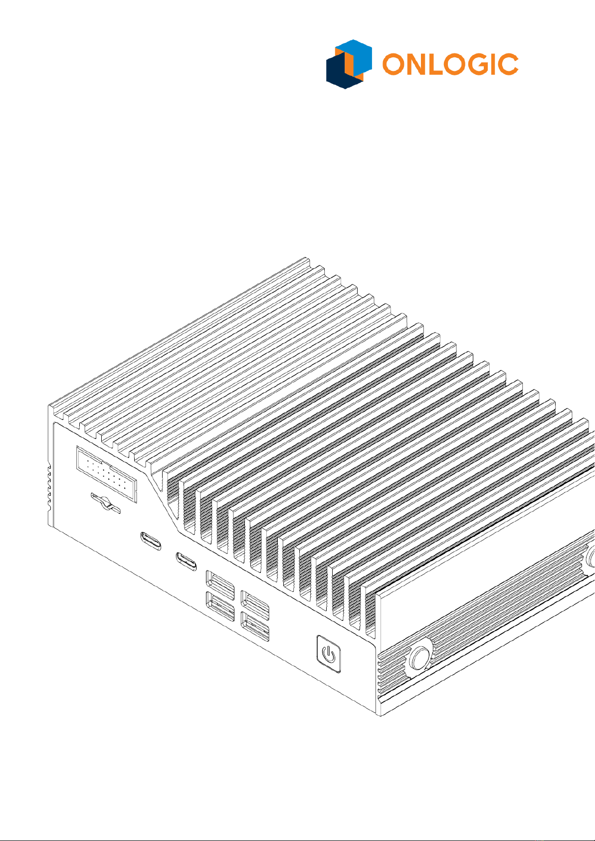
6. Caution, Hot Surface! It is normal for the unit to heat up and be hot to touch. Do not touch the
heatsink area or enclosure during operation and 30 minutes after shutdown allowing the unit
to cool down.
7. Ambient operating temperature must be between 0 °C to 50 °C with a non-condensing
relative humidity of 10-85%.
8. The device can be stored at temperatures between -10 °C to 85 °C. Note: Unit must be
stabilized within operating temperature before use, minimum 3HR.
9. Keep the device away from liquids and flammable materials. Not to be installed in a
hazardous environment.
10. Do not clean the device with liquids. The chassis can be cleaned with a dry cloth or duster
only. To prevent injury to self and/or damage to the device the unit must be powered down
and all connecting power and other peripherals shall be disconnected prior to cleaning.
11. Allow adequate space around all sides of the device for proper cooling and to not exceed its
maximum operating temperature limit. If the device is mounted to a vertical surface then
recommended device orientation is such that heatsink fins allow air to rise unobstructed.
Alternative orientations may result in reduced operational temperature range.
12. This device is intended for indoor operation only.
13. Caution, Risk of Electric Shock! Unit is powered by low voltage DC (Direct Current) only! Do
not connect AC (Alternating Current) into the device!
14. To power the device use only UL ITE Listed external power supplies with DC output of
12-24VDC, see specs for details.
15. Install the device only with shielded network cables.
16. The installer should be experienced in aftermarket installation and familiar with general
practices for installing electronics.
17. Service and repair of the device must be done by qualified skilled service personnel. This
includes, but is not limited to, replacement of the CMOS battery. Replacement CMOS battery
must be UL recognized and of a similar type as the original.
4

18. Proper disposal of the CMOS battery must comply with local governance.
19. Radio device is not intended for emergency service use.
20. To protect against excessive RF exposure, maintain at least 20cm from any user and the RF
antennas. Only use provided dual band PIFA antennas with 2dBi/2dBi gain (2.4 and 5Ghz)
for Wifi/BT.
21. This equipment is not suitable for use in locations where children are likely to be present.
WARNING: There is danger of explosion if the CMOS battery is replaced incorrectly. Disposal of
battery into fire or a hot oven, or mechanically crushing or cutting of a battery can result in an
explosion.
5

Précautions de sécurité, sauvegardes et informations
Ne pas ouvrir et modifier l'appareil ! L'appareil est conforme à diverses exigences nationales et
internationales en matière de sécurité, de CEM et d'environnement selon diverses normes.
La modification de l'appareil peut annuler les certifications, la garantie et/ou causer des blessures à
l'utilisateur.
Instructions d'utilisation et d'installation en toute sécurité
1. Des précautions doivent être prises lors de la manipulation de l'appareil pour éviter de se
blesser ou d'endommager l'appareil.
2. Lisez l'intégralité du manuel avant d'utiliser le produit.
3. Installez l'appareil en toute sécurité selon les instructions du manuel de l'utilisateur..
4. Le dispositif de montage au mur ou au plafond nécessite l'utilisation d'une plaque de montage
ou d'un support OnLogic.
5. Utilisez des vis à tête plate M3x0,5 mm pour fixer la plaque de montage ou les supports de
montage aux trous filetés au bas ou à l'arrière du châssis. Les vis doivent avoir une longueur
minimale de 4 mm. Ajoutez 1 mm de longueur de vis pour chaque mm d'épaisseur
supplémentaire de plaque ou de support au-delà de 1,5 mm.
6. Attention, surface chaude! Il est normal pour les unités de se réchauffer et de devenir
chaude au toucher. Évitez de toucher les surfaces de dissipation de chaleur ou le boîtier
pendant l’utilisation ou jusqu’à 30 minutes après l’arrêt pour permettre à l’unité de se refroidir.
7. La température ambiante de fonctionnement doit être comprise entre 0 °C et 50 °C avec une
humidité relative sans condensation de 10 à 85 %.
8. L'appareil peut être stocké à des températures comprises entre -10 °C et 85 °C. Remarque :
L'unité doit être stabilisée à la température de fonctionnement avant utilisation, minimum 3
heures.
9. Gardez l'appareil à l'écart des liquides et des matériaux inflammables. Ne pas installer dans un
environnement dangereux.
10. Ne nettoyez pas l'appareil avec des liquides. Le châssis peut être nettoyé uniquement avec un
chiffon sec ou un plumeau. Pour éviter de se blesser et/ou d'endommager l'appareil, l'appareil
doit être éteint et toutes les alimentations et autres périphériques doivent être déconnectés
avant le nettoyage.
11. Prévoyez un espace suffisant autour de tous les côtés de l'appareil pour un refroidissement
correct et pour ne pas dépasser sa limite de température de fonctionnement maximale. Si
l'appareil est installé sur une surface verticale, l'orientation recommandée de l'appareil est telle
que les ailettes du dissipateur thermique permettent à l'air de monter sans obstruction. Des
orientations alternatives peuvent entraîner une plage de températures de fonctionnement
réduite.
12. Cet appareil est destiné à une utilisation en intérieur uniquement
13. Avertissement! Risque de choc électrique ! L'unité est alimentée uniquement par une basse
tension CC (courant continu) ! Ne connectez pas le courant alternatif (courant alternatif) à
l'appareil !
6

14. Pour alimenter l'appareil, utilisez uniquement des alimentations externes répertoriées UL ITE
avec un puissance de sortie CC de 12-24 VCC, voir les spécifications pour plus de détails.
15. Installez l'appareil uniquement avec des câbles réseau blindés.
16. L'installateur doit avoir de l'expérience dans l'installation du marché secondaire et être
familiarisé avec les pratiques générales d'installation de l'électronique.
17. L'entretien et la réparation de l'appareil doivent être effectués par un personnel d'entretien
qualifié et qualifié. Cela inclut, mais sans s'y limiter, le remplacement de la batterie CMOS. La
batterie CMOS de remplacement doit être reconnue UL et d'un type similaire à l'original.
18. L'élimination appropriée de la batterie CMOS doit être conforme à la gouvernance locale
19. L'appareil radio n'est pas destiné aux services d'urgence..
20. Pour vous protéger contre une exposition RF excessive, maintenez au moins 20 cm de tout
utilisateur et des antennes RF. Utilisez uniquement les antennes PIFA double bande fournies
avec un gain de 2 dBi/2 dBi (2,4 et 5 Ghz) pour le Wifi/BT.
21. Cet équipement n'est pas adapté à une utilisation dans des endroits où des enfants sont
susceptibles d'être présents.
AVERTISSEMENT : Il existe un risque d'explosion si la pile CMOS n'est pas remplacée correctement.
L'élimination de la batterie dans le feu ou dans un four chaud, ou l'écrasement ou le découpage
mécanique d'une batterie peut entraîner une explosion.
7

1 - System Overview
1.1 - System Introduction
The Helix 401 (HX401) harnesses the enhanced power and capabilities of Intel “Alder Lake P” Core
and Celeron processors in a low profile fanless system built for the challenges of the IoT edge. With
support for four independent 4K displays, a 0°C to 50°C operating temperature range, and a wealth of
configuration options, the Helix 401 was engineered with versatility in mind. The systems also feature
compliance testing for IT Equipment EMC and Safety and pre-compliance testing for IEC 60601-1-2
(4th edition) medical immunity.
1.2 - Accessories
If you purchased additional items such as mounting brackets, power supplies or terminal block
connectors, they will be located in the system box or within the outer shipping carton.
All drivers and product guides can be found on the corresponding product page. For more
information on accessories and additional features, visit the Helix Product pages.
Helix 401 Product Page: https://www.onlogic.com/hx401/
8

1.3 - Product Specifications
OnLogic HX400 Series
Processor
Intel 12th Gen Alder Lake-P
Celeron, Core i3, i5, i7 up to 12-core (8P+4E) 16-thread
Memory
2x DD5-4800 SO-DIMM up to 64GB total (non-ECC)
Integrated Graphics
Intel® UHD Graphics for 12th Gen Intel® Processors (7305E, i3-1220PE)
Intel® Iris® Xe (i5-1250PE, i7-1270PE)
Front I/O
1x Power Button (LED Backlit)
4x USB 3.2 Gen 2
2x Type C USB 4 (40 Gb/s)*
3FF-Sim slot (Mapped to the B-Key)
1x DIO port Punch out
*Thunderbolt Certification Pending
Back I/O
2x Full size DisplayPort 1.4a
2x Gb LAN
Terminal Block Option - Punch out
2x Antenna punch outs
1x Serial/CAN Punch out
Barrel Jack with 19~24 V input
Expansion & Storage
1x M.2 2280/60/3042 B-Key (PCIe Gen 3 x1, USB 3.0, SATA III)
1x M.2 2230 E-key (Wi-Fi) (PCIe x1/ USB 2.0)
1x M.2 2280 M-key (PCIe Gen 4 x 4, SATA III)
Onboard Headers &
Connectors
1x Battery on a cable
1x Serial Header, RS 232/422/485
2x USB 2.0 (1x4 header)
16 Pin input for Terminal Block Power
Special Features
Watchdog timer
RTC
Onboard TPM - Infineon SLB9672
BIOS option for auto power-on
Optional Add On
Module
4G, CAN Bus, COM (RS-232/422/485), DIO (x4/x4), Terminal Block
Operating Systems
Windows 11 Pro 64 Bit*
Windows 10 IoT Enterprise 2021 LSC Value (Celeron/i3/i5) / High End (i7)
Ubuntu 22.04 Desktop / Server IOT
*Limited support - Refer to support.onlogic.com/documentation/onlogic-and-intel-collaboration/
LAN controller
1x Intel I219 and 1x Intel I210
Voltage Input
rated input: 19~24V via DC jack or 12~24V via Terminal Block, +/- 10% tolerance
9

Power Input
Barrel Jack with optional 4-pin Terminal Block (support for remote switch, Barrel
Jack covered when not in use.)
Power Protections
TVS for power input protection
Moderate disturbance protection with a TVS LC filter. Alternate DC supplies
should be IT equipment rated when possible.
Dimensions
160 x 123 x 50 mm
Weight
~1.20 kg / 2.65 lbs (System Only)
Motherboard
Dimensions
142 x 117 x 24mm max
Mounting Options
DIN
Wall
VESA
Thermal Standards,
Subject to Change
through RFI and RFQ
steps
System Operating Temperature: 0-50C
Board Operating Temperature: 0-65C
Storage Temperature: -10-85C
Operating Humidity: 0% - 90%
Radio Specifications when equipped with INT-9260 Wifi/BT (device for indoor use)
Frequency Bands
2.4GHz and 5GHz bands
Operating
Frequency
2400 - 2485 MHz
5150 - 5250 MHz, 5250 - 5350 MHz
5470 - 5725 MHz, 5725 - 5878 MHz
Channel spacing
/ Bandwidth
2.4GHz: 802.11b/g/n; 5 MHz / BT: 1MHz
Bandwidth: 20 MHz / 40 MHz
5 GHz: 802.11a/n/ac: 20, 40, 80, 160 MHz
RF output power
20dBm (2400-2485 MHz) IEEE 802.11b/g/n& BT
10dBm (2400-2485 MHz) BLE
23dBm (5150-5725 MHz) IEEE 802.11a/n/ac
13.98 dBm (5725-5875MHz) IEEE 802.11a/n/ac
Type of
Modulation
2.4GHz: DSSS/OFDM/FHSS
5 GHz: OFDM
Antenna
Specifications
ANT200 - PIFA type with 2dBi/2dBi gain on 2.4 & 5 GHz
Modes of
operation
Duplex (Tx/Rx)
Duty cycle
(access protocol)
As In: IEEE 802.11 a/b/g/n/ac
Version of
firmware
/software
Software Intel PROSet/Wireless WiFi Software
20..x and following versions for WIFI/BT
10

1.4 - Exterior Features and Dimensions
1.4.1 - Front I/O
The HX401 is pictured with the optional DIO module installed.
1.4.2 - Back I/O
The HX401 is pictured with the optional CAN module and optional terminal block connector shown
alongside the DC Barrel.
11

1.4.3 - Helix 401 Dimensions
12

1.5 - System Block Diagram
13

2 - I/O Definitions
2.1 - Front I/O Definition
The HX401 with the DIO option is pictured.
Power Button / Power LED
The front power button can be used to turn on and off the Helix system. The power button is a
momentary contact button with a blue LED backlight used to display the status of the system.
A single press while the system is on will initiate a graceful shutdown operation from the OS.
Pressing and holding the button for 4 seconds while the system is running will cause a hard reset
of the system. The system can be woken by a single press of the power button from any state.
The LED backlight will indicate the system status. A solid blue light indicates that the system is
powered in the S0 state. A flashing blue light indicates the system is in the sleep state. The LED is
off in S5 and deep sleep states.
SIM Card
A 3FF Subscriber Identity Module (SIM) card slot is present on the front panel of the HX401 allowing
native support for OnLogic 4G LTE modules. The SIM signals are connected to the M.2 B-Key internal
expansion slot.
The SIM slot is a Push-Push type receptacle. To insert or remove the SIM card from the front panel of
the Helix platform, please use a small implement to push the card into the slot until it clicks. To
14

remove the card, push with a small implement until the card clicks, then pull on the free end of the
card to remove it.
Type C USB 4 port
There are two USB 4 ports on the front panel of the HX401. This port is capable of linking up to
40Gb/s transfer rates.
●USB Type C connector
●Power output up to 5V/3A for the first port and 5V/1.5A for the second port. Power will be
allocated on a first-come first-serve basis between the first and second ports.
●Up to 40 Gbps data transfer rate
●DisplayPort 1.4 compliant in DisplayPort Alt Mode
●Supports SuperSpeed USB 10 Gbps; backwards compatible with SuperSpeed USB 5 Gbps and
USB 2.0.
Note: Type-C power sink mode is not supported on Helix 401.
USB 3.2
There are two dual stack USB 3.2 Gen 2 ports on the front panel of the Helix mainboard. Each port is
capable of linking at 10Gb/s transfer rates.
USB 2.0
There are two USB 2.0 headers on the Helix 401 mainboard. This port is capable of linking at 480
Mb/s transfer rates.
DIO option
The Helix platform supports an optional Isolated Digital I/O add-in card (OnLogic ADP120). This
option allows for integration of the Helix platform with existing PLC integrations or other digital logic
applications. For a complete explanation of features, operating voltages, and safety information,
please refer to the DIO expansion manual on the OnLogic support site.
https://www.onlogic.com/support/documentation/adp102-dio/
15

2.2 - Rear I/O definition
The HX401 with optional CAN installed. Additionally, the DC power barrel and terminal block power
input options are both shown.
Barrel Jack Power Connector
Mainboard power is applied to the Helix platform by way of a female barrel jack connector (OD:
5.5mm ID: 2.5mm. 12mm length ). The system is operational from 19V~24V. The maximum rated
current of the connector is 7A. Use a wire gauge that is rated for the operational current. See below
for on-board connector pinout.
Barrel Jack power pinout
16

Note: Located above the power barrel is a sheet metal punch-out for the plastic cable retention
clamp. To use this feature the sheet metal tab needs to be removed with the backplate uninstalled to
ensure the tab does not break off into the system.
DisplayPort 1.4a
Helix utilizes Intel’s Integrated Gen 12 processor graphics that power the onboard DisplayPorts 1.4a.
This means resolutions up to 4096x2160 @ 60Hz are supported on both outputs simultaneously. All
ports support Multi-Stream Transport (MST).
LAN1(vPRO) - Intel I219-LM
The Intel I219 LAN Port on Helix supports up to 1Gbps link speeds over standard shielded CAT5e or
CAT6 cables. The connector is the industry standard RJ45 connector. This port also features Intel’s
vPro(R) technology enabling remote out-of-band management and security features (requires Intel
Core i5 or higher). The LAN link state is shown by the two LEDs enclosed in the port. The description
is included below.
LAN2 - Intel I210-IT
The second LAN Port on Helix supports up to 1Gbps link speeds over standard shielded CAT5e or
CAT6 cables. The connector is the industry standard RJ45 connector. The LAN link state is shown by
the two LEDs enclosed in the port. The description is included below.
LED
State
Function
LED1
Blinking
Green
1Gb/s
activity
LED2
Blinking
Orange
100 Mb/s
activity
Blinking
Green
10 Mb/s
activity
LAN activity light description
17

COM DB9 Option
The serial port mode and voltage between Off/5V on Pin 9 on Helix can be selected in the BIOS
configuration. The serial ports support RS-232, RS-422, and RS-485 configurations. Refer to the BIOS
manual in Appendix C for configuration instructions.
Pin
RS-232
RS-422
RS-485
1
DCD
TX-
TX-/RX-
2
RX
TX+
TX+/RX+
3
TX
RX+
NC
4
DTR
RX-
NC
5
GND
NC
NC
6
DSR
NC
NC
7
RTS
NC
NC
8
CTS
NC
NC
9
RI/PWR
NC/PWR
NC/PWR
COM DB9 pinout
18

CAN DB9 option
The CAN port on Helix 401 supports CAN2.0 A/B at baud rates from 100-1000 kbaud. The system
CAN port is not internally terminated, and a properly terminated (120 Ohms, typical) cable should
be used. The communication protocol used to send and receive messages is detailed on the
support website.
Pin
Signal
1
CAN_2_L
2
CAN_1_L
3
GND
4
NC
5
NC
6
GND
7
CAN_1_H
8
CAN_2_H
9
NC
COM DB9 pinout
19

Terminal block power option
If the terminal block power option is selected, mainboard power is applied to the Helix platform
through a 4-pin terminal block connector (Mating part: Dinkle #2ESDVM-04P-BK or equivalent).
The system is operational from 12V~24V (HX401) [see section 4.3 for input voltage qualifications].
The maximum rated current of the connector is 15A per pin. Use a wire gauge that is rated for the
operational current. Cables should be properly terminated with wire ferrules. Do not use the terminal
block with tinned wire ends or solid core wire. See below for the connector pinout which is also
indicated on the terminal block mounting panel adjacent to the connector. Installation of DC Mains
connection shall only be performed by skilled personnel and in accordance with your local and
national electrical code (Example: NEC, CEC).
When using the remote switch connections with the terminal block option, mating power switch
cables should be a twisted-pair wire with floating shield to assure proper immunity to EMI/RFI. It is
recommended to keep wires at less than 3 meters in length. Switches should be momentary contact
type only.
Pin
Function
1
DC +
2
DC -
3
SW1
4
SW2
Terminal block power pinout
20
Table of contents
Other Onlogic Industrial PC manuals

Onlogic
Onlogic IGN500 User manual

Onlogic
Onlogic IGN100 User manual

Onlogic
Onlogic ML350G-10 User manual

Onlogic
Onlogic ML100G-51 User manual

Onlogic
Onlogic Factor 202 User manual

Onlogic
Onlogic HX310 User manual

Onlogic
Onlogic HX511 User manual

Onlogic
Onlogic Karbon 700 Series User manual

Onlogic
Onlogic ML350G-10 User manual

Onlogic
Onlogic K410 User manual