Onlogic Karbon 800 Series User manual

Karbon 800 Product Manual

Revision History
Date
Revision History
First release of Karbon 800 manual
1

1 - System Overview 5
1.1 - Accessories 5
1.2 - Product Specifications 6
1.3 - Exterior Features & Dimensions 9
1.3.1 - Front I/O 9
1.3.2 - Back I/O 9
1.3.3 - K801 System Dimensions 10
1.3.4 - K802 System Dimensions 10
1.3.5 - K803 System Dimensions 11
1.3.6 - K804 System Dimensions 11
1.4 - Motherboard Overview 12
1.4.1 - System Block Diagram 12
1.4.2 - Motherboard Features 13
2 - I/O Definitions 15
2.1 - Serial Ports 15
2.2 - DIO, CAN, Ext. Power Switch 16
2.2.1 - DIO Connection Diagram 17
2.4 - Status LEDs 18
2.5 - Automotive Ignition Power Sensing (IGN) 19
2.7 - Networking 20
2.9 - DisplayPort 20
2.10 - SIM Cards 20
2.11 - RTC Reset Button 21
2.12 - Modbay Expansion 21
2.12.1 - Modbay 4x LAN Expansion 21
2.12.2 - Modbay 4x PoE Expansion 21
2.12.3 - Modbay 3x M12 LAN Expansion 21
2.12.4 - Modbay 3x M12 PoE Expansion 22
2.12.5 - Modbay 2x 10Gb LAN Expansion 22
2

2.12.6 - Modbay 4x USB3 Expansion 22
3 - Motherboard Connectors 22
3.1 - M.2 2280 M-key 1 22
3.2 - M.2 2280 M-key 2 23
3.3 - M.2 3042/3052/2280 B-key 23
3.4 - M.2 2230 E-key 23
3.5 - mPCIe 23
3.6 - TPM Header 23
3.7 - Onboard PoE Header 23
3.8 - Aux Power Expansion Header 24
3.9 - SATA Headers 24
3.10 - PCIe Gen 5.0 x16 Connector 24
3.10.1 - PCIe x16 Riser (K803) 24
3.10.2 - PCIe x16 Riser (K804) 24
3.10.3 - Dual PCIe x8 Riser (K804) 24
3.11 - DDR4 SO-DIMM Slots 25
4 - Mounting Instructions 26
4.1 - Wall Mount Brackets 26
4.2 - Wall Mount Brackets with Vibration Isolation 27
4.3 - DIN Rail Mount Brackets 28
5 - OnLogic Microcontroller (MCU) 28
5.1 - Overview 28
6 - Power Management 29
6.1 - Wake-Up Events 29
6.2 - Protection Circuitry 29
7 - Regulatory Compliance 30
7.1 - CE 30
7.2 - FCC Statement 30
7.3 - ISED 30
3

7.4 - UKCA 30
7.5 - VCCI 30
8. Appendices 31
8.1 - Appendix A: Software Documentation 31
8.2 - Appendix B: System Thermal Results 31
8.2.1 - Testing Conditions 31
8.2.2 - Results Summary 31
8.3 Appendix C: PoE Power Budget 33
8.4 - Appendix D: Expansion Port Pinouts 34
8.4.1 - M.2 B-key Pinout 34
8.4.2 - M.2 M-key Pinout 35
8.4.3 - M.2 E-key Pinout 35
8.4.4 - mPCIe Pinout 36
8.5 - Appendix D: Errata 37
8.6 - Appendix E: Safety Information 37
8.6.1 - Safe use and installation instructions 37
8.6.2 - Précautions et guide d’installation 39
4

1 - System Overview
1.1 - Accessories
●5-pin Power Terminal Block Connector (Dinkle 2ESDVM-05P)
●20-pin DIO/CAN/SW Terminal Block Connector (Dinkle 0159-0320)
●SATA Power and Data Cables if not installed (OnLogic CBD123)
If you purchased additional items such as mounting brackets, power supplies or antennas, they will be
located in the system box or within the outer shipping carton.
All drivers and product guides can be found on the corresponding product page. For more information
on accessories and additional features, visit the Karbon 800 pages at:
US: https://www.onlogic.com/k801/
https://www.onlogic.com/k802/
https://www.onlogic.com/k803/
https://www.onlogic.com/k804/
EU: https://www.onlogic.com/eu-en/k801/
https://www.onlogic.com/eu-en/k802/
https://www.onlogic.com/eu-en/k803/
https://www.onlogic.com/eu-en/k804/
5

1.2 - Product Specifications
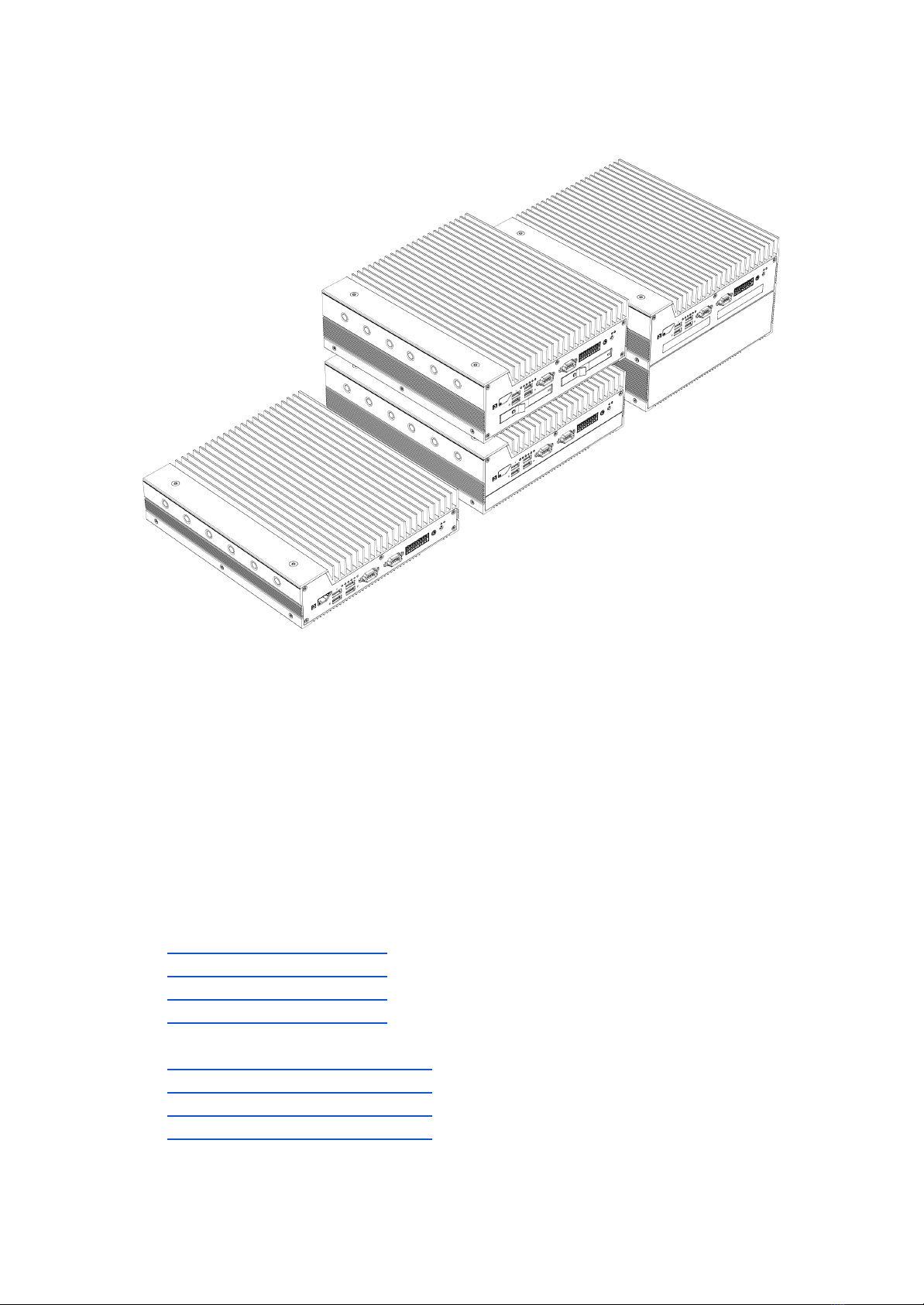
OnLogic Karbon 800 Series
Variants
K801 - High-Performance Rugged Low-Profile Computer
K802 - High-Performance Rugged Computer w/ModBay
K803 - High-Performance Rugged Computer w/PCIe
K804 - High-Performance Rugged Computer w/ModBay & PCIe
Processor
Intel 12th Gen Alder Lake-S (LGA1700)
Core i3, i5, i7 & i9 up to 16-core 24-thread
Memory
2x DDR4-3200 SO-DIMM up to 64GB total (non-ECC or ECC)
Chipset
Intel W680
Integrated Graphics
Intel UHD Graphics 730 (i3) or 770 (i5, i7, i9)
Front I/O
4x USB 3.2 Gen 2 Type-A
2x Serial RS-232/422/485
20-pin GPIO terminal block (DIO, CAN bus, Ext. switch)
1x 3.5 mm audio jack
2x 3FF Mini-SIM slots
1x External fan connector
2x Hot-swap drive bays (optional, K802 & K804)
8x Status LEDs
1x Power button
Back I/O
2x or 6x 2.5 GbE LAN (optional 2x PoE)
2x USB 3.2 Gen 2 Type-A
2x DisplayPort (full-size, DP 1.4, DP++, HDMI 1.4)
2x ModBay expansion slots (K802 & K804)
5-pin Power input
Expansion & Storage
1x M.2 2280 M-key (PCIe Gen 4 x4)
1x M.2 2280 M-key (PCIe Gen 4 x4, SATA)
1x M.2 3042/3052/2280 B-key (PCIe x2, SATA, USB 3.0, USB 2.0)
1x M.2 2230 E-key (PCIe x1, USB 2.0)
1x mPCIe (PCIe x1, USB 2.0)
1x PCIe Gen 5 x16 slot (K803 & K804)
2x 2.5” SATA (1x K803, 2x K802 & K804)
Special Features
User-Programmable OnLogic Microcontroller (MCU)
Automotive Ignition Power Sensing
Optional TPM 2.0 module (Nuvoton NPCT750)
Operating Systems
Windows 10, Windows 11, Ubuntu 22.04 (Kernel 5.16 and higher)
LAN Controllers
1x Intel I225-LM with AMT support
1x or 5x Intel I225-IT
Voltage Input
12 ~ 48V DC up to 30A (19 ~ 48V DC with PCIe expansion over 75W)
Dimensions
K801 = 240 x 50 x 267mm (9.45 x 1.97 x 10.51”)
K802 & K803 = 240 x 82 x 267mm (9.45 x 3.23 x 10.51”)
K804 = 240 x 143 x 267mm (9.45 x 5.63 x 10.51”)
Mounting
Wall Mount
Wall Mount with Vibration Isolation
DIN Rail Mount
6

Operating Temperature
-40°C ~ 70°C (35W TDP CPU)
-40°C ~ 50°C (65W TDP CPU)
Storage Temperature
-40°C ~ 85°C
Operating Humidity
10~95% relative, non-condensing
Storage Humidity
0~95% relative, non-condensing
Shock & Vibration
Shock: Tested according to IEC 60068-2-27 and MIL-STD-810H
Vibration: Tested according to IEC 60068-2-64 and MIL-STD-810H
Certifications
FCC 47 CFR Part 15 Subpart B (Class A)
EN 60950-1 & EN 63268-1
CISPR 32/EN 55032
CISPR 35/EN 55035
Radio Equipment Directive (2014/53/EU)
RoHS 3 (2015/863/EU)
WEEE Directive (2012/19/EU)
IEC 60068-2-27
IEC 60068-2-64
MIL-STD-810H
Power Immunity According to
E-Mark ISO 7637-2 & ISO 16750-2
EN 50121-3-2
IEC 60601-1-2, 4th ed.
EN 60945, 4th ed.
7

Radio Specifications when equipped with Intel AC 9260 Wi-Fi (device for indoor use)
Frequency Bands
2.4 GHz and 5 GHz bands
Operating Frequency
2400 - 2485 MHz
5150 - 5250 MHz, 5250 - 5350 MHz
5470 - 5725 MHz, 5725 - 5878 MHz
Channel spacing /
Bandwidth
2.4GHz: 802.11b/g/n; 5 MHz / BT: 1MHz
Bandwidth: 20 MHz / 40 MHz
5 GHz: 802.11a/n/ac: 20, 40, 80, 160 MHz
RF output power
20 dBm (2400-2485 MHz) IEEE 802.11b/g/n & BT
10 dBm (2400-2485 MHz) BLE
23 dBm (5150-5725 MHz) IEEE 802.11a/n/ac
13.98 dBm (5725-5875 MHz) IEEE 802.11a/n/ac
Type of Modulation
2.4 GHz: DSSS/OFDM/FHSS
5 GHz: OFDM
Type of Antenna
Reference antenna is PIFA type (2 dBi/2 dBi gain)
Modes of operation
Duplex (Tx/Rx)
Duty cycle (access
protocol)
As In: IEEE 802.11a/b/g/n/ac
8

1.3 - Exterior Features & Dimensions
1.3.1 - Front I/O
1.3.2 - Back I/O
9

1.3.3 - K801 System Dimensions
1.3.4 - K802 System Dimensions
10

1.3.5 - K803 System Dimensions
1.3.6 - K804 System Dimensions
11

1.4 - Motherboard Overview
1.4.1 - System Block Diagram
12

1.4.2 - Motherboard Features
Item
Description
A1
Power button
A2
Audio Jack
A3
8-bit Isolated DIO (4-in, 4-out), CAN bus, External Switch
A4
COM RS-232/422/485 ports (2x)
A5
USB 3.2 Gen 2 Type-A ports (4x)
A6
3FF Mini-SIM slots (2x)
A7
External fan header
A8
5-pin Power input with ignition sense
A9
Auxiliary power for GPU Power card
A10
DisplayPorts (2x)
A11
2.5 GbE LAN ports (2x or 6x)
13

A12
USB 3.2 Gen 2 Type-A ports (2x)
A13
PCIe Gen 5.0 x16 connector
A14
PCIe Aux power and fan control header
A15
CMOS battery
A16
TPM header
A17
Onboard PoE header
A18
SATA III ports (2x)
A19
M.2 2280 M-key (PCIe Gen 4 x4)
A20
ModBay connectors (2x)
A21
SATA power headers (2x)
A22
4-pin Aux power expansion (12V, 5V)
A23
mPCIe slot (PCIe Gen 3 x1, USB 2.0)
A24
DDR4 SO-DIMM slots (2x)
A25
M.2 2280 M-key slot (PCIe Gen 4 x4, SATA)
A26
M.2 2230 E-key slot (PCIe Gen 3 x1, USB 2.0)
A27
M.2 3042/3052/2280 B-key slot (PCIe Gen 3 x2, USB 3.0, USB 2.0)
14

2 - I/O Definitions
2.1 - Serial Ports
The serial ports on the Karbon 800 series motherboard support RS-232, RS-422 Full-Duplex, and
RS-485 half-Duplex configurations. The serial port communication mode can be selected in the BIOS
configuration. In addition, 5V & 12V power can be enabled on pin 9 in the same BIOS menu. Pin 9 is
rated to provide 250mA of current. Refer to the BIOS manual for configuration instructions.
Pin
RS-232
RS-422
RS-485
1
DCD
TX-
TX-/RX-
2
RX
TX+
TX+/RX+
3
TX
RX+
NC
4
DTR
RX-
NC
5
GND
NC
NC
6
DSR
NC
NC
7
RTS
NC
NC
8
CTS
NC
NC
9
RI/PWR
NC/PWR
NC/PWR
NC = Not Connected
15

2.2 - DIO, CAN, Ext. Power Switch
The Karbon 800 series 20-Pin header provides the following interfaces: 8-bit (4-in, 4-out) Digital Input
Output (DIO) or General Purpose Input Output (GPIO) with optically isolated terminals, one CAN bus
connection, and an optional external power switch connection.
The DIO is optically isolated, meaning that the terminal is separated from other motherboard features
for protection. The DIO terminal requires external power from a 5~48V DC source through Pin 20 with
GND to Pin 19 in order to function.
The Isolated Power Supply (ISO PSU) can be a voltage source from 5~48V to interface with external
digital IO. The maximum power draw from the supply should not exceed 0.6A under normal operating
conditions. Individual DOut pins will be damaged by loads in excess of 150mA. The ISO PSU must be
a DC Limited Power Source (LPS) power supply.
Mating power switch cables should be a twisted-pair wire with floating shield to assure proper
immunity to EMI/RFI. It is recommended to keep wires at less than 3 meters in length. Any remote
power switch connected between pins 1 and 2 should be momentary contact type only.
Pin
Definition
Pin
Definition
1
SW+
2
GND
3
GND
4
GND
5
GND
6
CANH
7
GND
8
CANL
9
GND
10
GND
11
In0
12
Out0
13
In1
14
Out1
15
In2
16
Out2
17
In3
18
Out3
19
V_DIO-
20
V_DIO+
16

2.2.1 - DIO Connection Diagram
17

2.4 - Status LEDs
LED
On
Off
Blink
Pulse
LEDs 1-4
Currently
selected
user mode
-
-
-
Watchdog
MCU is not
functioning
normally
MCU is not
functioning
normally
Firmware
bootloader
is active
MCU is
functioning
normally
Automotive
Ignition
Ignition input
to device is on
Ignition input
to device is off
-
-
Power
Device is on
Device is off
Device is
asleep
-
HDD
-
-
Internal
storage drive
activity
-
LED 1
LED 2
LED 3
LED 4
LED 5
LED 6
LED 7
LED 8
Color
White
Blue
White
White
White
White
White
White
Function
SSD Activity
Off = None
On = R/W
Power
Automotive
Ignition
Sensing
Watchdog
Timer & User
Configurable
User
Configurable
User
Configurable
User
Configurable
User
Configurable
18

2.5 - Automotive Ignition Power Sensing (IGN)
The Karbon 800 series 5-pin power input terminal offers automotive ignition sensing. The ignition
sensing timing for power on and off delays can be modified through OnLogic’s microcontroller (MCU)
using serial commands. These commands can be used to enable or disable the ignition sensing
feature, to set the timing delay for system startup after ignition is detected, and to set the timing delay
for system soft and hard shutdown after ignition is lost. For more information on ignition power
sensing, and instructions on how to use the serial commands from Windows or Linux, visit OnLogic’s
support site: https://www.onlogic.com/support/documentation/karbon-series-ignition-sensing/
Pin
Definition
1
12~48V DC Ignition
2
12~48V DC Input
3
12~48V DC Input
4
GND
5
GND
The system should always be used with the supplied 5-pin terminal block and power input should use
all 4 power pins (2~5).
The system is operational from 12V~48V DC and the maximum rated current of the connector is 15A
per pin. A minimum wire gauge of 16 AWG is recommended for 24V installations. Higher power or
lower voltage configurations may necessitate a heavier gauge power harness to reduce power loss in
the cabling. Always use a wire gauge that is rated for the operational current of your configuration.
When connecting to the mating terminal block plug, only multi-strand wire with a crimped ferrule end
should be used. The terminal block screws must be torqued to the rated value (0.5 Nm).
19
This manual suits for next models
5
Table of contents
Other Onlogic Industrial PC manuals

Onlogic
Onlogic HX310 User manual

Onlogic
Onlogic HX511 User manual

Onlogic
Onlogic ML350G-10 User manual

Onlogic
Onlogic ML100G-51 User manual

Onlogic
Onlogic ML350G-10 User manual

Onlogic
Onlogic IGN500 User manual

Onlogic
Onlogic ML510G-50 User manual

Onlogic
Onlogic HX401 User manual

Onlogic
Onlogic Factor 202 User manual

Onlogic
Onlogic K410 User manual
Popular Industrial PC manuals by other brands

ADLINK Technology
ADLINK Technology DLAP-3200-CF Series user manual

JHCTech
JHCTech FEBC-3158 user manual

Neousys Technology
Neousys Technology POC-40 Series user manual

Asus
Asus AAEON BOXER-6840-CFL user manual

Advantech
Advantech ITA-5710 Series Startup manual

AXIOMTEK
AXIOMTEK tBOX321-870-FL Series Quick installation guide