Gerät einbauen
Mounting the device
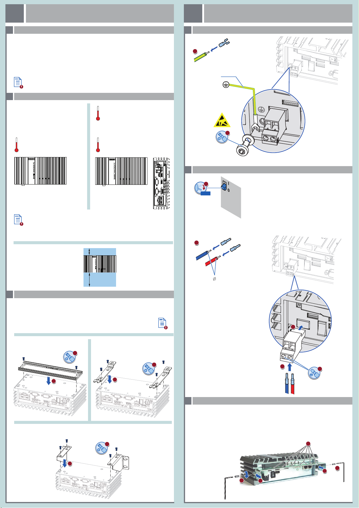
Gerät anschließen
Connecting the device
12
WICHTIG: Beachten Sie alle dem Gerät beiliegenden Dokumente und die Betriebsanleitung, bevor
Sie das Gerät einbauen und anschließen. Die vollständige Dokumentation des Geräts finden Sie auf
der beiliegenden DVD "Documentation and Drivers" und im Internet
(http://www.siemens.de/simatic-ipc-doku-portal).
IMPORTANT: observe all documents enclosed with the device and the operating instructions manual
before mounting and connecting the device. You find the complete documentation of the device on
the enclosed „Documentation and Drivers" DVD and on the internet
(http://www.siemens.com/simatic-ipc-doku-portal).
Das Handbuchsymbol weist auf detaillierte Informationen in der Betriebsanleitung hin.
The manual symbol refers to detailed information in the operating instructions.
0/OFF
DC 24 V
Power
Supply
L+M0,5 x 3
0.75 ... 2.5 mm2 = AWG18 ... AWG14
2,5 mm² = AWG14
T20
M4
Buchmontage
Upright mounting
Wandmontage
Wall mounting
Hutschienenmontage
Mounting on DIN rails
T20
T20
T20
Ensure that the mounting surface on the wall can bear four times the total
weight of the device, including fixing elements.
Use only the anchors and screws specified in the operating instructions.
Stellen Sie sicher, dass die Anschraubfläche an der Wand das Vierfache des Gesamtgewichts des
Geräts einschließlich Befestigungselemente tragen kann.
Verwenden Sie nur die in der Betriebsanleitung angegebenen Dübel und Schrauben.
Das Gerät darf nur an eine DC-24-V-Stromversorgung angeschlos-
sen werden, die den Anforderungen einer sicheren Kleinspannung
(SELV) gemäß der IEC/EN/DIN EN/UL 60950-1 bzw. IEC/EN/DIN
EN/UL 61010-2-201 entspricht.
Die Stromversorgung muss die Anforderung NEC Class 2 bzw. LPS
gemäß der IEC/EN/DIN EN/UL 60950-1 bzw.
IEC/EN/DIN EN/UL 61010-2-201 erfüllen.
The device must only be connected to a 24 VDC power supply
which satisfies the requirements of safety extra low voltage (SELV)
according to IEC/EN/DIN EN/UL 60950-1 or
IEC/EN/DIN EN/UL 61010-2-201.
The power supply must meet the NEC Class 2 or LPS requirement
in accordance with IEC/EN/DIN EN/UL 60950-1 or
IEC/EN/DIN EN/UL 61010-2-201.
M3 x 8
M3 x 8
≤0.8 Nm≤0.8 Nm
≤0.8 Nm
1. Schieben Sie die Blechlaschen der Kabelzugentlastung links und rechts in die zweite Nut von unten.
2. Befestigen Sie die Kabelzugentlastung links und rechts jeweils mit einem Gewindestift M3x8.
3. Sichern Sie die Anschlussleitungen nach dem Anschließen mit Kabelbinder an der Kabelzugentlastung.
1. Insert the metal plate of the strain relief left and right into the second to the last notch left and right.
2. Secure the strain relief on the left and right respectively with an M3x8 setscrew.
3. After connecting, secure the connection cables with cable ties to the cable strain relief.
Stromversorgung anschließen – Connecting the power supply
Schutzleiter anschließen – Connecting the protective earth
Zulässige Einbaulagen – Valid Mounting positions
1.1
1.2
2.2
Leitungen sichern (nur ATEX-Geräte) – Securing the cables (ATEX devices only)
2.3
2.1
Gerät anbauen – Mounting the device1.3
Vor Einbau und Inbetriebnahme – Before mounting and commissioning
60 °C (Basic, PCIe , - CFast)
0 °C
Load max. 3 W
50 °C (Basic, PCIe, - SSD/CFast)
0 °C
40 °C (All - SSD/CFast/HDD)
0 °C
Erforderlicher Freiraum um das Gerät
Free space required around the device
50 mm
> 50 °C: Install in RAL
Restricted Access Location - e. g. a lockable cabinet
Betriebsstätte mit beschränktem Zutritt - z. B. ein abschließbarer Schaltschrank
RAL =
100 mm
OR


