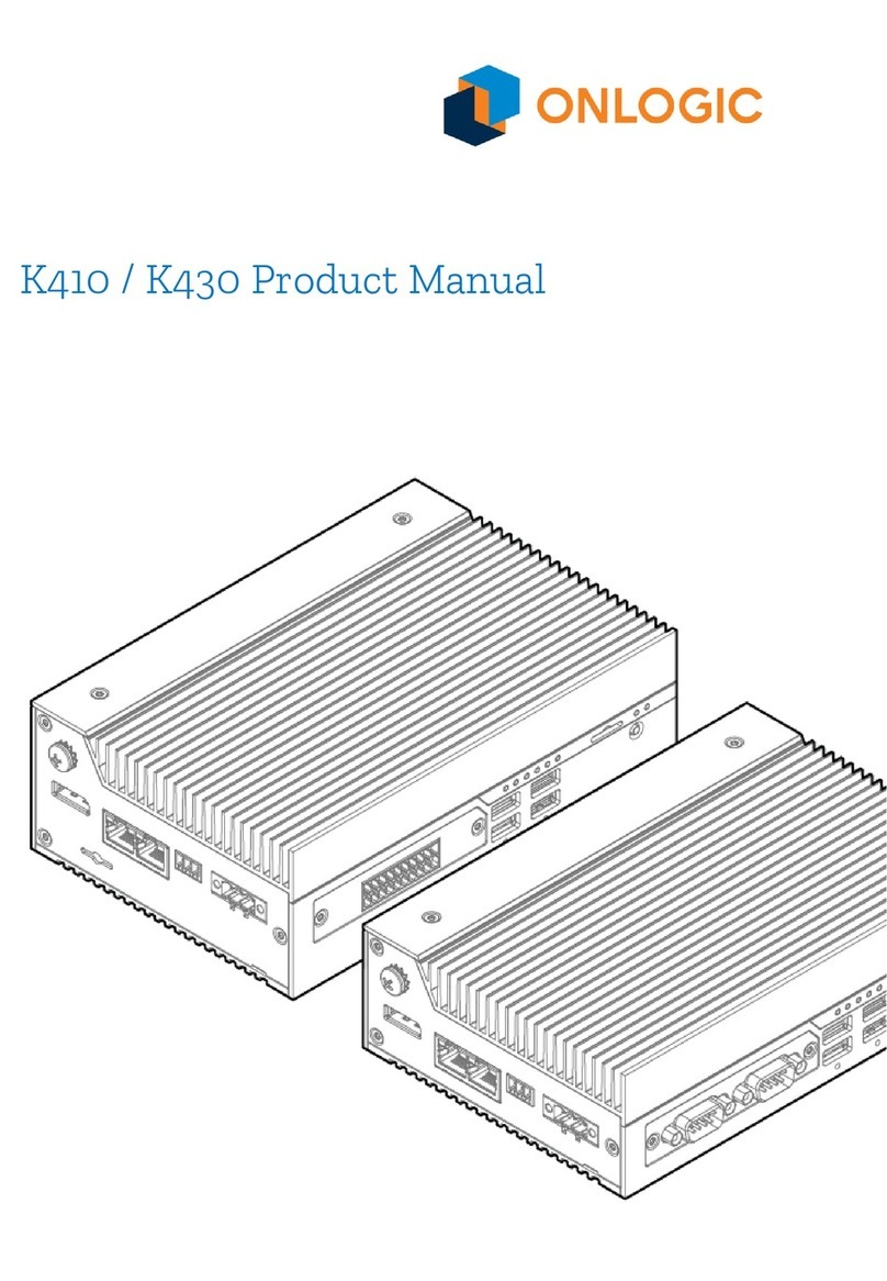
Onlogic Factor 202 User manual

FR202 Product Manual

Revision History
Revision History
Date
First release of FR202 manual
2022-09-27
Table of Contents
1 - System Overview 5
1.1 System Introduction 5
1.2- In-box Accessories 5
1.3 - Product Specifications 6
1.4 - Exterior Features and Dimensions 10
1.4.1 - Top I/O 10
1.4.2 - Bottom I/O 10
1.4.3 - Factor 202 Dimensions (FR202) 11
1.5 - System Block Diagrams 12
2 - I/O Definitions 13
2.1 - Top I/O Definition 13
USB-C Config Port (CM4 Update) 13
HDMI 13
USB 3.2 Gen1 5Gb/s 13
USB 2.0 13
2

Reset Button 14
Digital Inputs 14
“Active-Low” / Sinking Output-Compatible Input Wiring“Active-High” / Sourcing
Output-Compatible Input Wiring 15
Digital Outputs 16
2.2 Bottom I/O Definition 18
3-Pin Terminal Block Power Connector 19
5-Pin COM Terminal Block 19
LAN1 - CM4 output 19
LAN2 - Realtek RTL8153B 20
Analog/Temperature Inputs 22
SPI/I2C/UART/RS485 Header 24
Front Display 24
2.3 - Motherboard Connectors 26
M.2 B-Key 27
Boot Function Jumper Header 27
RTC Battery Header 28
Raspberry Pi Header 28
DSI Header (Not Populated) 29
CSI Header (Not Populated) 29
POE Add-on Connector 30
CM4 Headers 30
MCU Update Header 30
3 - Mounting Instructions 30
4 - Power Management 30
4.1 - Protection Circuitry 30
4.2 - Input Voltage Qualification 30
3

5 - Regulatory Compliance 31
5.1 - CE 31
5.2 - FCC Statement 31
5.3 - ISED 31
5.4 - UKCA 31
5.5 - VCCI 31
6. Appendices 33
6.1 - Appendix A: Power Consumption 33
6.3 - Appendix B: Software Documentation 34
6.4 - Appendix C: System Thermal Results 35
6.5 - Appendix D: Expansion Port Pinout 37
6.5.1 - M.2 B-Key (MODEM) 37
6.5.2 - M.2 B-Key (SATA) 38
6.6 Appendix E: Safety Information 39
6.6.1 Safe Use and Installation Instructions 39
6.6.2 Instructions d'utilisation et d'installation en toute sécurité 40
4

1 - System Overview
1.1 System Introduction
The Factor 202 (FR202) harnesses the power of the Raspberry Pi Compute Module 4, which
provides the core functionality of the Raspberry Pi 4. Combined with our own
industry-focused carrier board, and a custom-designed industrial chassis, the Factor 202 has
been engineered for today's industrial and embedded applications.
For use as a compact IoT gateway, edge device, or customizable industrial controller, the
Factor 202 is the industrial Raspberry Pi solution you've been waiting for.
1.2- In-box Accessories
●1x Power Terminal Block
●1x COM Terminal Block
●7x IO Terminal Block
If you purchased additional items such as mounting brackets, power supplies or terminal
block connectors, they will be located in the system box or within the outer shipping carton.
All drivers and product guides can be found on the corresponding product page. For more
information on accessories and additional features, visit the Factor 200 Series page.
5

Factor Series Page: https://www.onlogic.com/computers/industrial/fanless/factor-200/
Factor 202 Product Page: https://www.onlogic.com/fr202/
1.3 - Product Specifications
Model
Factor 202
(Includes FR201 IO)
System Dimensions
7.9" x 2.1" x 4.8"
201x 54 x 121 mm
CPU (on solder side of board)
Raspberry Pi CM4 Headers
Memory
CM4-dependent, up to 32GB
LAN Controller
1x Realtek RTL8153B (GbE)
1x from CM4 (GbE)
Expansion
1x M.2 2280 B-Key (USB 3.2 5Gb/s)
1x M.2 2280 B-Key (SATA III)
Back I/O
2x 1GbE LAN
1x 5-pin Serial (RS232/422/485)
3-pin Terminal Block with 12~24 V input
4x Analog input
(0~5V/0~10V/-5~5V/-10~10V/0-20mA/4-20mA/4-24mA)
2x Temperature input (RT100/1000)
1x SPI/I2C/UART/RS485 Header
Front I/O
1x USB 3.2 5Gb/s
2x USB 2.0
1x HDMI
1x USB-C for CM4 Programming
1x Reset button
16x Digital input (Isolated)
16x Digital Output (Isolated)
Onboard Headers & Connectors
1x Battery on a cable
1x Raspberry Pi Expansion Header (Female)
1x SPI TPM Header
1x CM4 Boot Mode Select
1x PoE PD Header
1x USB2 Modem Header
Voltage Input
12~24V or PoE PD
Power Input
3-pin Terminal Block or PoE PD via optional add-on
Operating Systems
Raspbian, Ubuntu 20.04
Special Features
RTC
TPM header - support TPM01
Support for 4G LTE and GPS expansion cards
Thermal Standards (Subject to
change through RFI and RFQ
steps)
Board Operating Temperature: -20-60C
Storage Temperature: -40-85C
Operating Humidity: 10% - 95% (non-condensing)
6

Extra Chassis Features
4 Antenna holes
DIN Rail Mount
Regulatory
SAFETY Listings + CB ( Intertek File 5019151)
IEC/UL/EN 62368-1, 61010-1, 61010-2-201
EMC CISPR 32/35 Class A
FCC Part 15 Class A
IEC/EN 60601-1-2:2014 Medical Immunity
Radio Equipment Directive (2014/53/EU) [Only applicable for
configurations with wireless transmitters and includes LTE/Wifi/BT
together]
RoHS 3 Directive (2015/863/EU)
WEEE Directive (2012/19/EU)
Radio Specifications when equipped with Raspberry Pi Wi-Fi (device for indoor use)
Cypress CYW43455
Frequency Bands
2.4 GHz Wifi
Operating Frequency
2400 to 2483.5 GHz (channelized)
Modulation Type
802.11b, 802.11g and 802.11n(HT20)
Channel spacing /
Bandwidth
2.4GHz: 802.11b/g/n; 5 MHz / BT: 1MHz
Bandwidth: 22 MHz
5 GHz: 802.11a/n/ac: 20, 40, 80, 160 MHz
RF output power
19 dBm (2400-2485 MHz) IEEE 802.11b/g/n & BT
10 dBm (2400-2485 MHz) BLE
23 dBm (5150-5725 MHz) IEEE 802.11a/n/ac
13.98 dBm (5725-5875 MHz) IEEE 802.11a/n/ac
Type of Antenna
1x Reference antenna is PIFA type (2 dBi/2 dBi gain) - external
terminal
Radio Specifications when equipped with Amit MDG100 (EU)
GPS Receiver
Operating frequency range: 1559 - 1610 MHz
GLONASS Receiver
Operating frequency range: 1559 - 1610 MHz
BDS Receiver
Operating frequency range: 1559 - 1610 MHz
Galileao Receiver
Operating frequency range: 1559 - 1610 MHz
QZSS Receiver
Operating frequency range: 1559 - 1610 MHz
GSM 900
Operating frequency range: 880 - 915 MHz, 925 - 960 MHz
Maximum output power: 33dBm rated
GSM 1800
Operating frequency range: 1710 - 1785 MHz, 1805 - 1880 MHz
Maximum output power: 30dBm rated
WCDMA Band 1
Operating frequency range: 1920 - 1980 MHz, 2110 - 2170 MHz
Maximum output power: 24dBm rated
7

WCDMA Band 8
Operating frequency range: 880 - 915 MHz, 925 - 960 MHz
Maximum output power: 24dBm rated
LTE FDD Band 1
Operating frequency range: 1920 - 1980 MHz, 2110 - 2170 MHz
Maximum output power: 23dBm rated
LTE FDD Band 3
Operating frequency range: 1710 - 1785 MHz, 1805 - 1880 MHz
Maximum output power: 23dBm rated
LTE FDD Band 7
Operating frequency range: 2500 - 2570 MHz, 2620 - 2690 MHz
Maximum output power: 23dBm rated
LTE FDD Band 8
Operating frequency range: 880 - 915 MHz, 925 - 960 MHz
Maximum output power: 23dBm rated
LTE FDD Band 20
Operating frequency range: 832 - 862 MHz, 791 - 821 MHz
Maximum output power: 23dBm rated
LTE FDD Band 28A
Operating frequency range: 703 - 733 MHz, 758 - 788 MHz
Maximum output power: 23dBm rated
LTE FDD Band 38
Operating frequency range: 2570 - 2620 MHz
Maximum output power: 23dBm rated
LTE FDD Band 40
Operating frequency range: 2300 - 2400 MHz
Maximum output power: 23dBm rated
E-GSM
Operating frequency range: 880 - 915 MHz
Maximum output power: 33dBm rated
DCS
Operating frequency range: 1710 - 1785 MHz
Maximum output power: 30dBm rated
8

Radio Specifications when equipped with Amit MDG200 (North America)
GPS Receiver
Operating frequency range: 1559 - 1610 MHz
GLONASS Receiver
Operating frequency range: 1559 - 1610 MHz
BDS Receiver
Operating frequency range: 1559 - 1610 MHz
Galileao Receiver
Operating frequency range: 1559 - 1610 MHz
QZSS Receiver
Operating frequency range: 1559 - 1610 MHz
WCDMA Band 2
Operating frequency range: 1850 - 1910 MHz, 1930 - 1990 MHz
Maximum output power: 24dBm rated
WCDMA Band 4
Operating frequency range: 1710 - 1755 MHz, 2110 - 2155 MHz
Maximum output power: 24dBm rated
WCDMA Band 5
Operating frequency range: 824 - 849 MHz, 869 - 894 MHz
Maximum output power: 24dBm rated
LTE FDD Band 12
Operating frequency range: 699 -716 MHz, 729 - 746 MHz Maximum
output power: 23dBm rated
LTE FDD Band 13
Operating frequency range: 777 - 787 MHz, 758 - 768 MHz
Maximum output power: 23dBm rated
LTE FDD Band 14
Operating frequency range: 788 - 798 MHz, 758 - 768 MHz
Maximum output power: 23dBm rated
LTE FDD Band 66
Operating frequency range: 1710 - 1780 MHz, 2100 - 2200 MHz
Maximum output power: 23dBm rated
LTE FDD Band 71
Operating frequency range: 663 -698 MHz, 617 - 652 MHz
Maximum output power: 23dBm rated
9

1.4 - Exterior Features and Dimensions
1.4.1 - Top I/O
1.4.2 - Bottom I/O
10

1.4.3 - Factor 202 Dimensions (FR202)
11

1.5 - System Block Diagrams
12

2 - I/O Definitions
2.1 - Top I/O Definition
USB-C Config Port (CM4 Update)
A USB-C port is provided to connect to the CM4 in USB 2.0 device mode, to update the bootloader
firmware or modify the eMMC filesystem in USB MSD mode.
A USB 2.0 host used to connect the FR201 must provide a 5V output in order to enable the USB-C
connection to the CM4. System power for the FR201 must also be provided separately via the main
power input or optional PoE.
USB 3.x, alternate function modes, and power output are not supported on this connector.
HDMI
FR201 uses the CM4’s integrated HDMI to drive the external HDMI Port. Resolutions up to 4096x2304
@ 60Hz are supported. CEC (Consumer Electronics Control) functionality is also supported,
depending on software configuration.
USB 3.2 Gen1 5Gb/s
One USB 3.2 Gen1 (5Gb/s) port is provided for peripherals or boot media.
By default, this port is disabled during system boot to ensure that the CM4 boots from internal media.
This behavior can be changed in software, or via the jumper header located in the center of the
motherboard. See the headers section of this manual for more information.
13

USB 2.0
Two USB 2.0 ports are provided for peripheral usage. Together, they may deliver a maximum of 2A at
5V, depending on peripheral and device configuration.
Reset Button
The front reset button can be used to trigger a reset of the CM4. The reset button is a momentary
contact button that is tool-accessible through the chassis.
Digital Inputs
Pin
DI 1
DI 2
1
VCC
VCC
2
DI0
DI8
3
DI1
DI9
4
DI2
DI10
5
DI3
DI11
6
DI4
DI12
7
DI5
DI13
8
DI6
DI14
9
DI7
DI15
10
GND
GND
DI terminal pinout
16 optically isolated digital inputs are provided via 2 10-pin terminal block connecters (Dinkle
0221-2010 or equivalent). Performance is optimized for 12-24V operation.
Each group of 4 inputs (DI0-3, DI4-7, DI8-11, and DI12-15) is software-configurable to active-high or
active-low. The active-low configuration activates internal pull-ups to the VCC pin of the same header.
If the active-low configuration for a pin group is desired, customers must connect both VCC and GND
of that group’s connector. If the active-high configuration is used, customers must connect the GND.
Inputs are active at voltages exceeding 11.5V and inactive below 4.5V.
14

“Active-Low” / Sinking Output-Compatible Input Wiring
“Active-High” / Sourcing Output-Compatible Input Wiring
15

Digital Outputs
Pin
DI 1
DI 2
1
VCC
VCC
2
DO0
DO8
3
DO1
DO9
4
DO2
DO10
5
DO3
DO11
6
DO4
DO12
7
DO5
DO13
8
DO6
DO14
9
DO7
DO15
10
GND
GND
DO terminal pinout
16 optically isolated digital outputs are provided via 2 10-pin terminal block connecters (Dinkle
0221-2010 or equivalent). Performance is optimized for 12-24V operation. Operating voltage should
not exceed 24V. Each output has a 0.5A resettable fuse.
Each group of 4 outputs (DO0-3, DO4-7, DO8-11, and DO12-15) is software-configurable to sourcing or
sinking (high- or low-side switched). For all configurations, customers must supply a VCC and GND
connection on the same connector as the outputs in use. No power is sourced for the outputs through
the system power connector.
16

Sourcing Output Wiring
17

Sinking Output Wiring
2.2 Bottom I/O Definition
18

3-Pin Terminal Block Power Connector
Mainboard power is applied to the FR201 platform by way of a 3-pin terminal block connector (Mating
part: Dinkle 2ESSM-03P or equivalent). The system is operational from 8V~24V. The maximum rated
current of the connector is 15A per pin. Use a wire gauge that is rated for the operational current. See
below for on-board connector pinout.
Note: DC power input should not be connected when the system is supplied with POE power via the
ADP122 add-on module.
Pin
Definition
1
GND
2
Chassis/Earth GND
3
12~24V VDC Input
3-Pin terminal power pinout
5-Pin COM Terminal Block
The serial port supports RS-232, RS-422, and RS-485 configurations by way of a 5-pin terminal block
connector (Mating part: Dinkle 0221-2005 or equivalent). The mode can be selected from within the
operating system using available configuration tools. See FR201 software documentation for details.
Pin
RS-232
RS-422
RS-485
1
GND
GND
GND
2
NC
TX-
TX-/RX-
3
NC
RX-
NC
4
RX
TX+
TX+/RX+
5
TX
RX+
NC
COM terminal pinout
LAN1 - CM4 output
The CM4 LAN Port on FR201 supports up to 1Gbps link speeds over standard shielded CAT5e or
CAT6 cables. The connector is the industry standard RJ45 connector. The LAN link state is shown by
the two LEDs enclosed in the port. Activity is also indicated by the LAN1 LED on the side of the
19

system. The default configuration is included below, but the behavior can be customized using the
CM4 boot configuration file.
PoE PD (power input) support is available optionally by adding the ADP122 FR200 POE PD module to
the system. Note: DC power input should not be connected when the system is supplied with POE
power via the ADP122 add-on module.
Speed/Act
State
Speed
State
Function
Off
Off
LAN link is not
established
Green
(Flash for
Activity)
Off
10 Mb/s data
rate
Green
(Flash for
Activity)
Orange
100 Mb/s data
rate
Off
Orange
(Slow
Blink)
1000 Mb/s data
rate
LAN activity light description
LAN2 - Realtek RTL8153B
The second LAN Port on FR201 supports up to 1Gbps link speeds over standard shielded CAT5e or
CAT6 cables. The connector is the industry standard RJ45 connector. The LAN link state is shown by
the two LEDs enclosed in the port. The description is included below. Activity is also indicated by the
LAN2 LED on the side of the system.
Speed/Act
State
Speed/Act
State
Function
Off
Off
LAN link is not
established
Green
(Flash off
for
Activity)
Green
(Flash on
for activity)
/
Orange
10 Mb/s data
rate
Green
(Flash on
for
Activity)
Green
(Flash on
for Activity)
/ Orange
100 Mb/s data
rate
Green
(Flash off
Green
(Flash on
1000 Mb/s data
rate
20
This manual suits for next models
1
Table of contents
Other Onlogic Industrial PC manuals

Onlogic
Onlogic ML350G-10 User manual

Onlogic
Onlogic ML100G-51 User manual

Onlogic
Onlogic ML510G-50 User manual

Onlogic
Onlogic Karbon 800 Series User manual

Onlogic
Onlogic IGN500 User manual

Onlogic
Onlogic HX401 User manual

Onlogic
Onlogic K410 User manual

Onlogic
Onlogic HX511 User manual

Onlogic
Onlogic HX310 User manual
Onlogic
Onlogic IGN100 User manual
Popular Industrial PC manuals by other brands

Advantech
Advantech UTC-310GP-ATB0E user manual

Siemens
Siemens SIMATIC IPC427E operating instructions

Psion Teklogix
Psion Teklogix 8525 user manual

Kontron
Kontron ThinkIO Duo Hardware guide

Siemens
Siemens SIMATIC Rack PC 840 V2 Getting started

Moxa Technologies
Moxa Technologies UC-7101-LX quick start guide