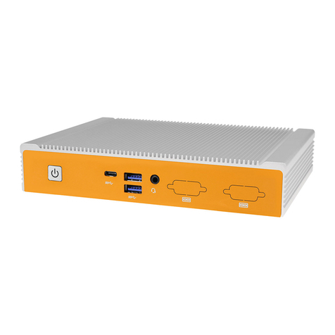
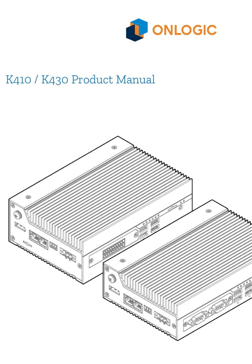
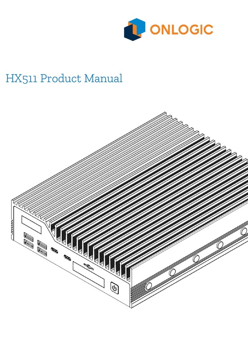
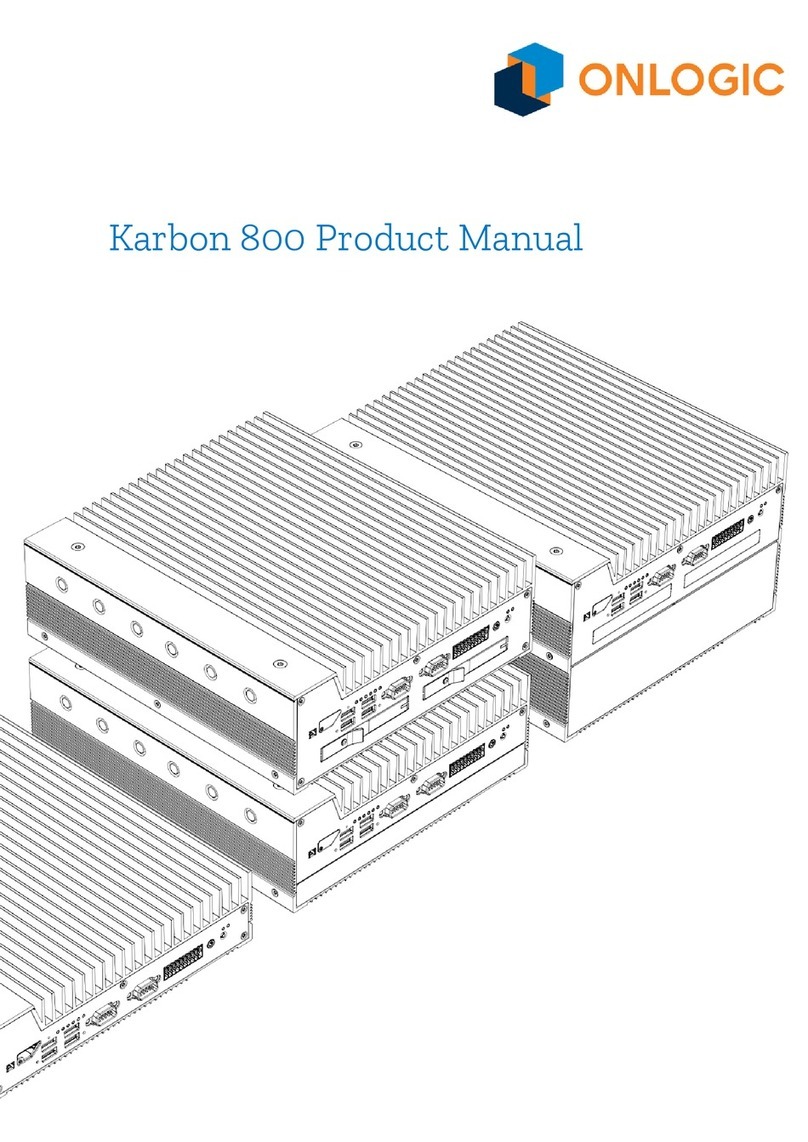
Onlogic IGN500 User manual

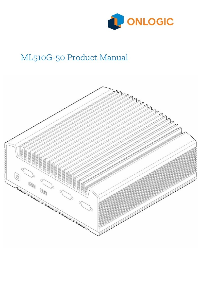
ML350 Manual
The not so quick, quick start guide.
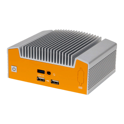
IGN500 Manual
Version 1
US Oce
Phone: +1 802 861 2300
Email: [email protected]
www.onlogic.com
EU Oce
Phone: +31 85 2733760
Email: [email protected]
www.onlogic.com

IGN500 Industrial Computer
2
IGN500 Manual
About OnLogic .......................................................................3
Contact Information. . . . . . . . . . . . . . . . . . . . . . . . . . . . . . . . . . . . . . . . . . . . . . . . . . . . . . . . . . . . . . . . . 3
Regulatory Compliance and Safety Information..........................................4
Safe Use and Installation Instructions ..................................................4
1 - What’s In The Box..................................................................7
2 - System Overview ..................................................................8
2.1 - System Diagram................................................................8
2.2-SystemSpecications ...........................................................9
2.3 - Mounting Hole Pattern .........................................................10
2.4 - Mounting Guide ...............................................................11
3 - Motherboard Overview............................................................12
3.1 - Jumpers and Headers Guide ....................................................13
3.2-ConguringJumpers ...........................................................14
3.3 - Onboard Headers .............................................................15

IGN500 Industrial Computer
3
About OnLogic
OnLogicispoweringinnovationwithhighlycongurableembeddedandIoTcomputersengineeredforreliabil-
ity. Businesses worldwide depend on our solutions to operate in the toughest environments while tapping into
theevolvingIndustrialInternetofThings.
ThisguidewillintroduceyoutotheIGN500industrialfanlesscomputerandsystemspecications.Fortechnical
questions or support, please reach out via our contact information below.
Youhavealotofchoiceswhenchoosingcomputerhardware.TheOnLogicTeamwantstothankyoufortrust-
ingourcomponentstomeetyourapplicationneeds.TheIGN500istheresultofinputfrompartnerslikeyou.
We’veworkedhardtocreateasystemthatmeetsthevariedneedsofindustrialandIoTcomputingandwe’ve
manufactured this system under our strict quality assurance and immunity standards to serve you best. If you
have any concerns about the quality or performance of this product, please contact us directly or visit our sup-
port pages at US: https://www.onlogic.com/company/support/ or EU: https://www.onlogic.com/eu-en/company/
support/.
Contact Information
OnLogic Global
35ThompsonStreet,
SouthBurlington,VT05403
USA
+1 802 861 2300
OnLogic Europe
De Boedingen 39
4906 BA Oosterhout
TheNetherlands
+31 88 5200 700

IGN500 Industrial Computer
4
Regulatory Compliance and Safety Information
Regardingequipment:IndustrialFanlessPCmodel(s):xxxxxIGN500xxxxx(wherexisanyalphanumeric
character,“-”orblankdesignatingcongurationdierences)
Safe Use and Installation Instructions
1. Donotopenormodifythedevice.ThedeviceusescomponentsthatcomplywithFCCandCE
regulations.Modicationofthedevicemayvoidthesecertications.
2. Install the device securely. Be careful handling the device to prevent injury and do not drop.
3. Wallorceilingmountingdevicerequiresuseofamountingplateorbracket.Plateorbracketmustbeof
metalconstructionandhaveaminimumthicknessof1mm.
4. UseM3x0.5mmFlatHeadscrewstoattachmountingplateormountingbracketstothreadedholeson
bottom or rear of chassis. Screws should be minimum length of 4mm. Add 1mm of screw length for
everymilimeterofadditionalthicknessofplateorbracketbeyond1.5mm.
5. Ambientoperationaltemperaturemustbebetween0°Cto40°C,orwithsomecongurations
0 °C to 50 °C , with a non-condensing relative humidity of 10-90%.
6. Thedevicecanbestoredattemperaturesbetween-40°Cto85°C.
7. Keepthedeviceawayfromliquidsandammablematerials.
8. Donotcleanthedevicewithliquids.Thechassiscanbecleanedwithacloth.
9. Allow at least 2 inches of space around all sides of the device for proper cooling. If device is mounted
toverticalsurfacethenrecommendeddeviceorientationsothatheatsinknsallowairtorise
unobstructed. Alternative orientations may result in reduced operational temperature range.
10. Thisdeviceisintendedforindooroperationonly.
11. UseULListedexternalpowersupplywithratedoutput12Vd.c.,5Amin.
12. Installthedeviceonlywithshieldednetworkcables.
13. Serviceandrepairofthedevicemustbedonebyqualiedservicepersonnel.Thisincludes,butisnot
limited to, replacement of the CMOS battery. Replacement CMOS battery must be of the same type as
original.
14. Proper disposal of CMOS battery must comply with local governance.
Revision History
Revision History Date
Release of IGN500 manual 7/31/2019

IGN500 Industrial Computer
5
WARNING:ThereisdangerofexplosioniftheCMOSbatteryisreplacedincorrectly.Disposalof
batteryintoreorahotoven,ormechanicallycrushingorcuttingofabatterycanresultinan
explosion.
Précautions et guide d’installation
1. Nepasouvriroumodierl’appareil.L’appareilutilisedescomposantsconformesauxréglementations
FCCetEC.Lamodicationdel’appareilpeutannulercescertications.
2. Installezl’appareilentoutesécurité.Soyezprudentlorsdelamanipulationdel’appareilpouréviterles
blessures et ne pas faire tomber.
3. Lemontageaumurouauplafondnécessitel’utilisationd’uneplaquedemontageoud’unsupport.La
plaqueoulesupportdoitêtreenmétaletdoitavoiruneépaisseurminimalede1mm.
4. UtilisezdesvisàtêteplateM3x0,5mmpourxerlaplaquedemontageoulessupportsauxtrousletés
situésaubasouàl’arrièreduchâssis.Lesvisdoiventavoirunelongueurminimalede4mm.Ajoutez
1mmdelongueurdevispourchaquemmd’épaisseursupplémentairedeplaqueoudesupport
dépassant1,5mm.
5. Latempératureambianteopérationnelledoitsesituerentre0°Cet40°C,oupourcertaines
congurations,entre0°Cet50°Cavecunehumiditérelativesanscondensationentre10et90%.
6. Laplagedetempératuresdestockagedoitêtrede-40°Cà85°C.
7. Gardezl’appareilàl’écartdesliquidesetdesmatièresinammables.
8. Nenettoyezpasl’appareilavecdesliquides.Lechâssispeutêtrenettoyéavecunchion.
9. Laissezaumoins5cmd’espaceautourdetouslescôtésdel’appareilpourunrefroidissementcorrect.
Sil’appareilestmontésurunesurfaceverticale,l’orientationrecommandéeesttellequelesailettes
du dissipateur de chaleur permettent à l’air de monter sans obstruction. Les orientations alternatives
peuvententraîneruneréductiondelaplagedetempératuredefonctionnement.
10. Cetappareilestconçuuniquementpouruneutilisationenintérieur.
11. UtilisezunealimentationexternelistéeULavecunesortienominalede12Vd.c.,5Amin.
12. Installezl’appareiluniquementavecdescâblesréseaublindés.
13. L’entretienetlaréparationdel’appareildoiventêtreeectuéspardupersonnelqualié.Celainclut,
sans toutefois s’y limiter, le remplacement de la batterie CMOS. La batterie CMOS de remplacement doit
être du même type que l’originale.
14. Lamiseaurebutdesbatteriesusagéesdoitêtreréaliséeconformémentauxréglementations
environnementales.
WARNING:ATTENTION:Risqued’explosionsilabatterieestremplacéeparunebatteriedetype
incorrect.Lesbatteriedoiventêtrerecycléesdanslamesuredupossible.
IGN500 Industrial Computer
6
Declaration of Conformity
CE
inaccordancewiththefollowingDirective(s):
ElectromagneticCompatibility(2014/30/EU)
Low-Voltage(2014/35/EU)
RoHS2(2011/65/EU)
RadioEquipment(2014/53/EU)-Onlyapplicableforcongurationswithwirelesstransmitters
herebydeclarethat:Equipment:IndustrialFanlessPCmodel(s):xxxxxIGN500xxxxx(wherexisany
alphanumericcharacter,“-”orblankdesignatingcongurationdierences)isinconformitywiththe
applicable requirements of the following documents:
FCC
Thisdevicecomplieswithpart15oftheFCCrulesasaClassAdevice.Operationissubjecttothefollowing
twoconditions:(1)thisdevicemaynotcauseharmfulinterferenceand(2)thisdevicemustacceptany
interference received, including interference that may cause undesired operation.
ISED(Innovation,ScienceandEconomicDevelopmentCanada)
ThisdevicecomplieswithIndustryCanadalicense-exemptRSSstandard(s).Operationissubjecttothe
followingtwoconditions:(1)thisdevicemaynotcauseinterference,and(2)thisdevicemustacceptany
interference, including interference that may cause undesired operation of the device.
LeprésentappareilestconformeauxCNRd’IndustrieCanadaapplicablesauxappareilsradioexempts
delicence.L’exploitationestautoriséeauxdeuxconditionssuivantes:(1)l’appareilnedoitpasproduire
debrouillage,et(2)l’utilisateurdel’appareildoitacceptertoutbrouillageradioélectriquesubi,mêmesile
brouillage est susceptible d’en compromettre le fonctionnement.
• EN 55032:2015/AC:2016 Class A
• EN 55035:2017
• EN 61000-3-2:2014 Class D
• EN 61000-3-3:2013
• EN 61000-4-2:2009
• EN
61000-4-3:2006+A1:2008+A2:2010
• EN 61000-4-4:2012
• EN 61000-4-5:2014+A1:2017
• EN 61000-4-6:2014+AC:2015
• EN 61000-4-8:2010
• EN 61000-4-11:2004+A1:2017
• EN 62368-1:2014 / A11:2017
• EN301489-1V2.2.0(2017-03)Draft
• EN301489-17V3.2.0(2017-03)Draft

IGN500 Industrial Computer
7
1 - What’s In The Box
IGN500 Built & Tested System
Any Selected Accessories
Ifyoupurchasedadditionalitemssuchasspecicmountingbrackets,
powersuppliesorantennas,theywillbelocatedinthesystemboxor
within the outer shipping carton.
All drivers and product guides can be found on the corresponding
product page at:
US: https://www.onlogic.com/ign500/
EU: https://www.onlogic.com/eu-en/ign500/
+

IGN500 Industrial Computer
8
2 - System Overview
2.1 - System Diagram
Power Button
USB 3.0 COMBOAudioJack
DisplayPort
DCJack Gb LAN
USB 3.0
HDMI
142.0 mm
111.0 mm
61.5 mm
USB 2.0 Optional Serial RS232/422/485
Optional DIO

IGN500 Industrial Computer
9
2.2 - System Specications
IGN500
NUC-8265U
Processor Intel® 8th Gen i5-8265U
Memory Capacity 32 GB
Supported Features
Memory Type DDR4 SO-DIMM
Processor Graphics Intel® UHD Graphics 620
Supported OS Windows 10, Ubuntu 18
Power Input 12VDCJack
Expansion 1xM.22230E-Key(PCIex1+USB)
Storage 1xM.2socket(2242/2260,SATA/PCIex4)
Ethernet 1xIntel®I219V+1xRealtekRTL8111G
Rear I/O
1xDCIn-Jack
2xRJ45(w/LED)
1xHDMI(maxresolutionupto4Kx2Kat30Hz)
2xDisplayPort(maxresolutionupto3840x2160at60Hz)
2xUSB3.0
1xDIO4in/4out(optional)
Front I/O
1xCOMBOAudioJack(Headphone+MIC)
1xUSB3.0
RS-232/422/485COM(optional)
Environment
OperatingTemperature:0°C~50°C
OperationHumidity:10%~95%
StorageTemperature:-40°C~85°C
StorageHumidity:0%~95%
Mounting Wall,DIN,VESA-100(Additionalmountinghardwarerequired)

IGN500 Industrial Computer
10
2.3 - Mounting Hole Pattern
156.1 mm
146.1 mm
40.5 mm
3.7 mm
76.2 mm
12.7 mm
Ø4.6 mm
Ø8 mm
Ø4.6 mm
10.0 mm

IGN500 Industrial Computer
11
2.4 - Mounting Guide
Desk Mounting
Step 1:Attachwallmountbracketstochassis
Step 2:Markandprepholesinsurfaceformounting
Step 3: Fastensystemtosurface
VESA Mounting
Step 1: Install 4 VESA Screws into your display/surface
Step 2:AttachVESAbrackettothechassis
Step 3: Hangcombinedsystemandbrackettodisplay/surface
DIN Rail Mounting
Step 1:Attachwallmountingbracketstothechassis
Step 2:AttachDINRailClipstothemountingbrackets
Step 3: Clip system to the DIN Rail

IGN500 Industrial Computer
12
3 - Motherboard Overview

IGN500 Industrial Computer
13
3.1 - Jumpers and Headers Guide
Number Location Function
1 M2M_1 M.2Key-MSocket2242/2260(SATA/PCIex4)
2 M2E_1 M.2Key-ESocket2230(USB+PCIex1)
3 USB2_3_4 USB 2.0 Connector
4 COM1 COMPortHeader(RS232/422/485)
5 PANEL1 System Panel Header
6 LPC1 LPC Debug Header
7 PWR_JP1 ATX/ATModeJumper
8 USB3_3 USB 3.1 Gen 1 Port
9 AUDIO1 AudioJack
10 SATA_PWR1 SATAPowerOutputConnector
11 SATA3_1 SATA3Connector
12 M2_SEL2 M.2 Select
13 CLRMOS1 BIOS Reset
14 DC_JACK1 DC-InJack
15 DISPLAY1 DisplayPort(MaxResolution3840x2160@60Hz)
16 DP2 DisplayPort(Top)
HDMI1 HDMIPort(Bottom)(MaxResolution4Kx2K@30Hz)
17 LAN2 RJ-45LANPort(Top)
USB3_2 USB3.1Gen1Port(Bottom)
18 LAN1 RJ_45 LAN Port
USB3_1 USB 3.1 Gen 1 Port
19 DDR4_B1 Memory Slots
DDR4_A1
BackSide PWR_BTN1 Power Button
FAN1 FanConnector

IGN500 Industrial Computer
14
Refertothefollowingdiagramsforconguringjumpersandonboardheaders.
3.2 - Conguring Jumpers
CLRMOS1
TheCLRMOS1jumperloadsthedefaultBIOSsettings.Shortpins1-2fornormaloperation.Shortpins
2-3tocleartheCMOSandresetthesystemsetupcongurationtodefaultsettings.Ifyouexperience
challenges powering up, short pins 2-3 to reset the BIOS.
PWR_ JP1
AT=Autopoweron.
ATX=Noautopoweron.
Clear CMOSNormal
AT Mode ATX Mode

IGN500 Industrial Computer
15
3.3 - Onboard Headers
An onboard header is a connection on the motherboard that permits connecting a peripheral component to
anexternalportonthesystem.
USB2_3_4
TheUSB2_3_4connectorsupportstwoUSBports.
COM1
ThemotherboardincludesanI/OCOMPortat0x3F8IRQ4andcansupportRS232/RS422/RS485.
RS232 RS422 RS485
1 DCD TX(negative) RTX(negative)
2RXD# TX(positive) RTX(positive)
3TXD# RX(positive) N/A
4DTR RX(negative) N/A
5 GND GND GND
6 DSR N/A N/A
7RTS N/A N/A
8CTS N/A N/A
9 RI N/A N/A
10 Key N/A N/A
15V_USB
3Data(Negative)
5Data(Positive)
7GND
9NC
25V_USB
4Data(Negative)
6Data(Positive)
8GND
10 Key

IGN500 Industrial Computer
16
PANEL1
Thesystempanelheadercontrolsthepoweronandresetbuttons,aswellasHardDriveLEDs(HDLED)and
PowerLEDs(PLED).
LPC1
ThemotherboardincludesaLowPinCount(LPC)debugheaderasatroubleshootingsolution.
1HDLED(Positive)
3HDLED(Negative)
5GND
7RESET
9GND
2PLED(Positive)
4PLED(Negative)
6PWRBTN
8GND
10 None
1PCICLK
3FRAME
5PCIRST
7LAD3
93V
11 LAD0
13 None
15 3V_SB
17 GND
2GND
4SMBusClock
6SMBus Data
8LAD2
10 LAD1
12 GND
14 S_PWRDWN
16 SERIRQ
18 GND
Table of contents
Other Onlogic Industrial PC manuals

Onlogic
Onlogic Karbon 800 Series User manual

Onlogic
Onlogic K410 User manual

Onlogic
Onlogic ML100G-51 User manual

Onlogic
Onlogic ML350G-10 User manual

Onlogic
Onlogic HX401 User manual

Onlogic
Onlogic HX310 User manual

Onlogic
Onlogic Karbon 700 Series User manual

Onlogic
Onlogic IGN100 User manual

Onlogic
Onlogic ML510G-50 User manual

Onlogic
Onlogic ML350G-10 User manual
Popular Industrial PC manuals by other brands

AXIOMTEK
AXIOMTEK tBOX810-838-FL Series user manual

Avalue Technology
Avalue Technology ERS-AT270-A2 Quick reference guide

Beckhoff
Beckhoff C6250-0070 Installation and operating instructions

Boser
Boser BBS-1080S manual

Moxa Technologies
Moxa Technologies V2406-24I Series Hardware user manual

Vecow
Vecow GPC-1000 Series user manual