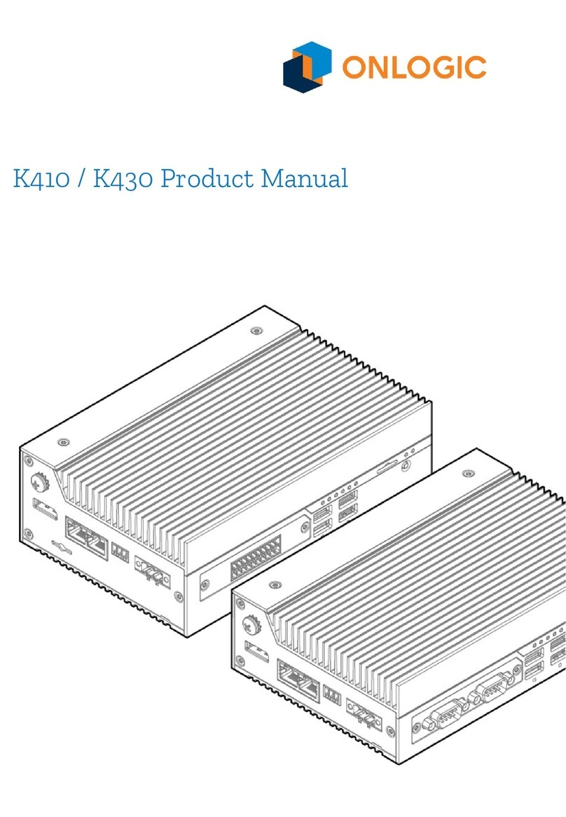
Onlogic Karbon 700 Series User manual

Karbon 700 Product Manual

Revision History
Revision History
Date
First release of Karbon 700 manual
08/22/2019

1 - System Overview 5
1.1 - Accessories 5
1.2 - Product Specifications 6
1.3 - Exterior Features and Dimensions 8
1.3.1 - Front I/O 8
1.3.2 - Back I/O 8
1.3.3 - Karbon 700 Dimensions (K700-SE) 9
1.3.4 - Karbon 700 Dimensions with PCIe Expansion (K700-X2) 9
1.4 - Motherboard Overview 10
1.4.1 - System Block Diagram 10
1.4.2 - Motherboard Features 11
2 - I/O Definitions 13
2.1 - Serial Ports 13
2.2 - DIO 14
2.2.1 - DIO Connection Diagram 15
2.3 - Remote Power Switch 15
2.4 - LEDs 16
2.5 - Automotive Ignition Power Sensing (IGN) 17
2.6 - CAN Bus 17
2.6.1 - CAN Bus Connection Diagram 18
2.7 - LAN 18
3 - Mounting Instructions 19
3.1 - Wall Mount 19
3.2 - Wall Mount with Vibration Isolation 20
4 - Microcontroller 21
4.1 - Overview 21
5 - Power Management 21

5.1 - Wake-Up Events 21
5.2 - Protection Circuitry 22
6 - Test Reports 22
6.1 - ISO 7637-2 and ISO 16750-2 Summary 22
6.1.1 - Electrical Supply/Load Voltage Drop Data 22
6.1.2 - Paragraph 4.11 Voltage Withstand Test Results 23
6.2 - Electrical Supply/Load Disturbance Data 23
6.2.1 - Paragraph 4.7 Reverse Voltage Test Results 23
6.2.2 - Paragraph 4.9 Open Circuit Test Results 24
6.2.3 - Paragraph 4.10 Open Circuit Test Results 24
6.2.4 - Paragraph 4.12 Open Circuit Test Results 24
6.3 - Conducted Transient Data 25
6.4 - EN 50121-3-2 Summary 25
6.4.1 - ESD Immunity Data 25
6.4.2 - Radiated Immunity Data 25
6.4.3 - Electrical Fast Transient Immunity Data 26
6.4.4 - Surge Immunity Data 26
6.4.5 - Conducted Immunity Data 26

1 - System Overview
1.1 - Accessories
●5-pin Power Terminal Block Connector (Dinkle PN: 2ESDVM-05P)
●2-pin Remote Switch Terminal Block Connector (Dinkle PN: EC350V-02P)
●3-pin CAN bus Terminal Block Connector (Dinkle PN: EC350V-03P)
●10-pin DIO Terminal Block Connector (Dinkle PN: EC350V-10P)
●5-pin Terminal Block to 6-pin Molex Adapter (OnLogic PN: CBP133)
●SATA Power and Data Cables If Not Installed (OnLogic PN: CBD123)
If you purchased additional items such as mounting brackets, power supplies or antennas,
they will be located in the system box or within the outer shipping carton.
All drivers and product guides can be found on the corresponding product page. For more
information on accessories and additional features, visit the Karbon 700 pages at:
US: https://www.onlogic.com/K700-SE/
https://www.onlogic.com/K700-X2/
EU: https://www.onlogic.com/eu-en/K700-SE/
https://www.onlogic.com/eu-en/K700-X2/

1.2 - Product Specifications
Karbon 700 Series
Processor
Intel 8th Gen Coffee Lake & 9th Gen Coffee Lake Refresh
LGA1151 Celeron, Pentium, Core & Xeon E up to 80W
Memory
2 DDR4-2666 SO-DIMM up to 64GB total (non-ECC or ECC)
Chipset
Intel C246
Integrated Graphics
Intel UHD Graphics 610/630
Front I/O
1 Power button
4 USB 3.1 Gen 1 Type A
2 Serial RS-232/422/485
1 3.5 mm audio jack (mic-in, stereo out)
8-bit isolated DIO (4-in, 4-out)
8 Status LEDs
2-pin Remote switch
1 Mini-SIM slot (2FF)
2 Hot-swap drive bays (optional)
Back I/O
5-pin Power input
3 Full-size DisplayPort 1.2 supporting DP++ and HDMI 1.4
3 Gb LAN (2 Gb Mode A PoE optional)
2 USB 3.1 Gen 1 Type A
2 ModBay™ expansion slots
3-pin CAN bus 2.0B
1 External fan connector
Expansion & Storage
1 M.2 2280 M-key (PCIe x4, SATA)
1 M.2 2230/60/80 M-key (PCIe x2)
1 M.2 2230 E-key (PCIe x1, USB 2.0)
2 Full-length mPCIe (1 duplexed with mSATA)
2 2.5” SATA SSD/HDD drives (hot-swap optional)
1 PCIe x16 or 2 PCIe x8 with K700-X2 expansion chassis and riser
Max. PCIe dimensions: 211 x 129 x 41 mm (8.31 x 5.08 x 1.61 in)
Special Features
OnLogic Microcontroller (MCU)
Automotive Ignition Power Sensing
SuperCap backup for RTC battery
Optional TPM 2.0 module (Nuvoton NPCT750)
Operating Systems
Windows 10, Ubuntu 18.04
LAN Controllers
1 Intel I219-LM with AMT support
2 Intel I210-AT
Voltage Input
9~48 VDC with 5-pin terminal block
Dimensions
K700-SE: 240 x 242 x 82 mm (9.45 x 9.53 x 3.23 in)
K700-X2: 240 x 242 x 143 mm (9.45 x 9.53 x 5.63 in)

Mounting
Wall/surface (bottom)
Wall/surface with Vibration Isolation (bottom)
Temperature
Operating Temperature: -40°C ~ 70°C (35W TDP CPU)
-40°C ~ 50°C (60W TDP CPU)
-40°C ~ 40°C (80W TDP CPU)
Storage Temperature: -40°C ~ 85°C
Humidity
Operating Humidity: 10~95% relative
Storage Humidity: 0~95% relative
Shock & Vibration
Shock: Tested according to IEC 60068-2-27 and MIL-STD-810G
Vibration: Tested according to IEC 60068-2-64 and MIL-STD-810G
Certifications
FCC 47 CFR Part 15
Low-Voltage (2014/35/EU)
Electromagnetic Compatibility (2014/30/EU)
Radio Equipment (2014/53/EU) - Only applicable
for configurations with wireless transmitters
EN 55032
EN 55035
RoHS 3 (2015/863/EU)
WEEE Directive (2012/19/EU)
IEC 60068-2-27
IEC 60068-2-64
MIL-STD-810G
Power Immunity According to
E-Mark 7637-2 & 16750-2
EN 50121

1.3 - Exterior Features and Dimensions
1.3.1 - Front I/O
1.3.2 - Back I/O

1.3.3 - Karbon 700 Dimensions (K700-SE)
1.3.4 - Karbon 700 Dimensions with PCIe Expansion (K700-X2)

1.4 - Motherboard Overview
1.4.1 - System Block Diagram

1.4.2 - Motherboard Features
Item
Function Description
A1
Power button
A2
SIM card holder
A3
Remote switch
A4
8-bit isolated DIO (10 pins, 4-in, 4-out)
A5
3.5 mm combo audio connector
A6
COM RS-232/422/485 ports
A7
USB 3.1 Gen 1 Type A
A8
3 RJ45 GbE LAN connector (2 PoE optional with A25 module)
A9
USB 3.1 Gen 1 Type A

A10
Full-size DisplayPort with CEC support
A11
3-pin CAN bus
A12
5-pin power input with ignition sense
A13
External fan connector
A14
ModBay™ connector 1
A15
ModBay™ connector 2
A16
PCIe riser slot (x16 lanes)
A17
SATA 1
A18
SATA 2
A19
M.2 2230/60/80 M-key
A20
M.2 2230 E-key
A21
mPCIe/mSATA
A22
mPCIe
A23
M.2 2280 M-key
A24
RTC backup battery
A25
Onboard PoE module header
A26
TPM module header
A27
2 SATA power
A28
2 SO-DIMM memory slots

2 - I/O Definitions
2.1 - Serial Ports
The serial port mode and voltage between Off/5V/12V on Pin 9 on Karbon 700 can be selected in the
BIOS configuration. The serial ports support RS-232, RS-422, and RS-485 configurations. Refer to the
BIOS manual for configuration instructions.
Pin
RS-232
RS-422
RS-485
1
DCD
TX-
TX-/RX-
2
RX
TX+
TX+/RX+
3
TX
RX+
NC
4
DTR
RX-
NC
5
GND
NC
NC
6
DSR
NC
NC
7
RTS
NC
NC
8
CTS
NC
NC
9
RI/PWR
NC/PWR
NC/PWR
NC = Not Connected

2.2 - DIO
The Karbon 700 Digital Input Output (DIO) or General Purpose Input Output (GPIO) terminals are
optically isolated. This means that the terminal is separated from other motherboard features for
protection. The DIO terminal requires external power from a 5~48VDC source through Pin 10 with
GND to Pin 1 in order to function.
Pin 1
Pin 2
Pin 3
Pin 4
Pin 5
Pin 6
Pin 7
Pin 8
Pin 9
Pin 10
GND
In 4
In 3
In 2
In 1
Out 4
Out 3
Out 2
Out 1
Power

2.2.1 - DIO Connection Diagram
The Isolated Power Supply (ISO PSU) can be a voltage source from 5V-48V to interface with external
digital IO. The max power draw from the supply should not exceed 0.6A under normal operating
conditions. Individual DOut pins will be damaged by a load in excess of 150mA. The ISO PSU can only
be a DC Limited Power Source (LPS) power supply.
2.3 - Remote Power Switch
Pin
Definition
1
GND
2
Power
Mating power switch cables should be a twisted-pair wire with floating shield to assure proper
immunity to EMI/RFI. It is recommended to keep wires at less than 3 meters in length. Switches
should be momentary contact type only.

2.4 - LEDs
LED
On
Off
Blink
Pulse
HDD
-
-
Internal
storage drive
activity
-
Power
Device is on
Device is off
Device is
asleep
-
Automotiv
e Ignition
Ignition input
to device is
on
Ignition input
to device is off
-
-
Watchdog
MCU is not
functioning
normally
MCU is not
functioning
normally
Firmware
bootloader
is active
MCU is
functioning
normally
LEDs 1-4
Currently
selected
user mode
Currently
selected
user mode
-
-

2.5 - Automotive Ignition Power Sensing (IGN)
The K700 5-pin power input terminal offers automotive ignition sensing. The ignition sensing timing
for power on and off delays can be modified through OnLogic’s microcontroller (MCU) using serial
commands. These commands allow setting the delay on startup after ignition is detected, the delay
until soft and hard shutdown when ignition is lost, and enabling/disabling ignition sensing. For more
information on ignition power sensing, and instructions on using these serial commands from
Windows or Linux, visit OnLogic’s tech support site on the Karbon series ignition sensing.
Pin
Definition
1
9~48 VDC Ignition
2
9~48 VDC Input
3
9~48 VDC Input
4
GND
5
GND
The system should always be used with the supplied 5-pin terminal block. The total system power
draw and input voltage will determine whether only two of the power pins can be used. Configurations
with high wattage CPUs (65W or more), PoE ModBay cards, or GPU expansion must use all 4 power
pins. Low voltage supplies (9~12V) should also use all 4 power pins. If only two of the input pins are
used, it is recommended to use a jumper between the populated and open connection.
2.6 - CAN Bus
See Section 4 for information on how to drive the CAN bus.
Pin
Definition
1
GND
2
CAN L
3
CAN H

2.6.1 - CAN Bus Connection Diagram
2.7 - LAN
The K700 provides three GbE LAN ports. Two of these LAN ports have an optional PoE function using
an optional onboard module. When the PoE module is installed, the two PoE ports will provide up to
32W of combined power. This power output is enough to support a single port up to 25.5W (IEEE
802.3at), two ports up to 15.4W each (IEEE 802.3af), or two ports with a combined draw up to 32W
(e.g. 7W and 25W). PoE is enabled by adding the optional PoE Expansion card.
LED
Color
State
Condition
Link
-
Off
LAN link is
not
established
Green
On
LAN link is
established
Blinking
LAN activity
occurring
Speed
-
Off
10 Mb/s data
rate
Green
On
100 Mb/s
data rate
Yellow
On
1000 Mb/s
data rate

3 - Mounting Instructions
3.1 - Wall Mount
Step 1: Attach wall mounting brackets to the chassis using:
Screw type: M4X0.7 T10 TORX 120
Length: 10 mm
Step 2: Mark and prepare holes on the surface for mounting
Step 3: Fasten system to surface. The mounting bracket systems are required to secure 3x the
hanging weight of the computer system. The mating substrate must be capable of maintaining the
same rating.

3.2 - Wall Mount with Vibration Isolation
Step 1: Attach wall mounting brackets to the chassis using:
Screw type: M4X0.7 T10 TORX 120
Length: 10 mm
Step 2: Mark and prepare holes on the surface for mounting
Step 3: Fasten system to surface
This manual suits for next models
2
Table of contents
Other Onlogic Industrial PC manuals

Onlogic
Onlogic ML510G-50 User manual

Onlogic
Onlogic HX511 User manual

Onlogic
Onlogic ML350G-10 User manual

Onlogic
Onlogic IGN100 User manual

Onlogic
Onlogic ML100G-51 User manual

Onlogic
Onlogic K410 User manual

Onlogic
Onlogic HX401 User manual
Onlogic
Onlogic IGN500 User manual

Onlogic
Onlogic Karbon 800 Series User manual

Onlogic
Onlogic ML350G-10 User manual
Popular Industrial PC manuals by other brands

Aaeon
Aaeon UP Xtreme quick start guide

ViewSonic
ViewSonic EP4220 user guide

Moxa Technologies
Moxa Technologies UC-8200 Series Hardware user manual

Norco
Norco EMB-3501 user manual

Smitec
Smitec POSYC Series Instructions for installation, use and maintenance manual

Janz Tec
Janz Tec emPC-CX+/C-1047UE Hardware manual