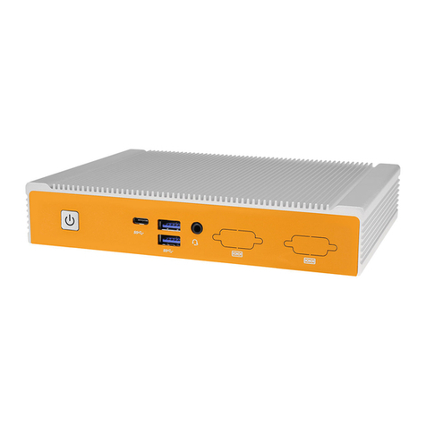
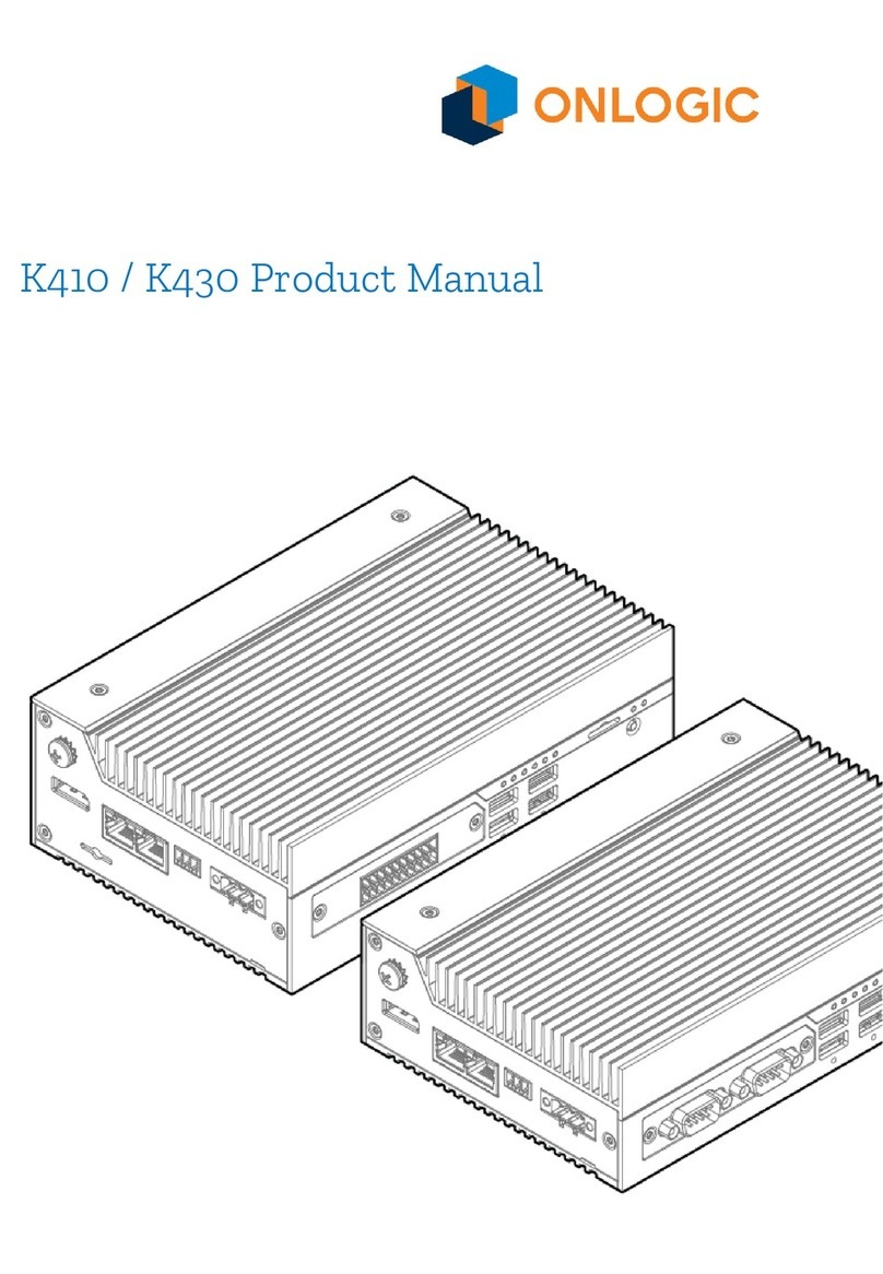
Onlogic HX511 User manual

HX511 Product Manual

Revision History
Revision History
Date
First release of HX11 manual
06/06/2023
Table of Contents
1 - System Overview 4
1.1 System Introduction 4
1.2- In-box Accessories 4
1.3 - Product Specifications 5
1.4 - Exterior Features and Dimensions 8
1.4.1 - Front I/O 8
1.4.2 - Back I/O 8
1.4.3 - Helix 511 Dimensions (HX511) 9
1.5 - System Block Diagram 10
2 - I/O Definitions 11
2.1 - Front I/O definition 11
2.2 Rear I/O definition 15
2.3 - Motherboard Connectors 19
3 - Mounting Instructions 22
3.1 - Wall Mount & DIN Rail Mounting 22
3.2 - VESA Mounting 23
4 - Power Management 24
4.1 - Wake-Up Events 24
4.2 - Protection Circuitry 24
5. Appendices 25
5.1 - Appendix A: Power consumption 25
5.3 - Appendix B: BIOS manual and Drivers 27
5.4 - Appendix C: System Thermal Results 27
5.4.1 Test Conditions 27
5.4.2 Test Methodology 27
5.4.3 Test Results 28
5.4.4 Test Result Summary 28
5.5 - Appendix D: Expansion port pinout 28
5.5.1 - M.2 B-Key 28
5.5.2 - M.2 E-Key 29
2

5.5.3 - M.2 M-Key 31
5.5.4 - mPCIe 32
5.6 Appendix E: Regulatory Compliance 33
5.6.1 CE 33
5.6.2 FCC Statement 33
5.6.3 ISED 33
5.6.4 UKCA 33
5.6.5 VCCI 33
5.7 Appendix F: Safety Precautions, Safeguards & Information 34
5.7.1 Safe use and installation instructions 34
5.7.2 Précautions et guide d’installation 35
3

1 - System Overview
1.1 System Introduction
The OnLogic HX511 expands on the Helix product range, and leverages Intel® 12th generation Alder
Lake PS processing into a powerful fanless system.
The HX511 offers increased compute power and visual processing capabilities, encased in
Hardshell™Fanless Technology. Additionally, it offers optional expansion options via reliable,
cableless add-on cards. With quad video output, a wide power range, and high processing power, the
HX511 is equipped to handle a wide variety of applications.
1.2- In-box Accessories
●4x Rubber Feet
If you purchased additional items such as mounting brackets, power supplies or terminal
block connectors, they will be located in the system box or within the outer shipping carton.
All drivers and product guides can be found on the corresponding product page. For more
information on accessories and additional features, visit the HX511 product page at
https://www.onlogic.com/hx511/.
4

1.3 - Product Specifications
Model
HX511
System Dimensions
8.86" x 2" x 6.97"
225 x 50.8 x 177 mm
System Weight
4.94 lbs
2.24 kgs
Board Dimensions
8.7" x 6.1"
221 x 156 mm
CPU (on solder side of board)
Socket LGA 1700 - Alder Lake PS
PCH
PS Integrated
Memory
2 x SO-DIMM DDR5 (2 x 32GB max Dual Channel) 64 GB Total
LAN Controller
1x Intel i225-LM -with AMT
1x Intel I225-IT
Expansion
1x M.2 2280/3042/3052 B-Key (PCIe x2, USB 3.2 5Gb/s, SATA III)
1x M.2 2230 E-key (Wi-Fi) (PCIe / USB 2.0)
1x M.2 2280 M-key (PCIe x 4, SATA III)
Back I/O
2x Full size DisplayPort 1.4 2x Gb LAN (2 x Intel)
2x USB 3.2 10 Gb/s
4-pin Terminal Block (12 ~ 24 V input)
Optional dual CAN card
Optional single COM (RS-232/422/485) card
Front I/O
1x Power button with LED indicator
1x 3FF-Sim slot (Mapped to the B-Key)
4x USB 3.2 10Gb/s
Optional 3 COM (RS-232/422/485) add-in card
Optional DIO add-in card
2x Thunderbolt 4 (40 Gb/s) USB Type C
Onboard Headers & Connectors
1x Battery on a cable
1x internal power header (5V, 12V)
Voltage Input
12~24V
Power Input
4-pin Terminal Block (supports remote switch)
BIOS
Insyde
Operating Systems
Windows 10 IOT 2021 LTSC, Ubuntu 22.04 LTS, Yocto, Window 11
Special Features
Watchdog timer
RTC
PTT in BIOS
On-board TPM 2.0
Support for Vision Processing Units
Support for 4G LTE and GPS expansion cards
5

Thermal Standards (Subject to
change through RFI and RFQ
steps)
System Operating Temperature: 0-50C
Storage Temperature: -10-85C
Operating Humidity: 0% - 90% (non-condensing)
Extra Chassis Features
6 Antenna holes
Wall Mount
DIN Rail Mount
VESA Mount
Regulatory Certifications
FCC 47 CFR Part 15 Subpart B (Class A)
EN 60950-1 & EN 63268-1
CISPR 32/EN 55032
CISPR 35/EN 55035
Radio Equipment Directive (2014/53/EU)
WEEE Directive (2012/19/EU)
RoHS 3 (2015/863/EU)
IEC 60601-1-2, 4th ed. - EMC Ready
EN 60945, 4th ed.
IEC/UL/EN 62368-1
Radio Specifications when equipped with Intel AC 9260 Wi-Fi (device for indoor use)
Frequency Bands
2.4 GHz and 5 GHz bands
Operating Frequency
2400 - 2485 MHz
5150 - 5250 MHz, 5250 - 5350 MHz
5470 - 5725 MHz, 5725 - 5878 MHz
Channel spacing /
Bandwidth
2.4GHz: 802.11b/g/n; 5 MHz / BT: 1MHz
Bandwidth: 20 MHz / 40 MHz
5 GHz: 802.11a/n/ac: 20, 40, 80, 160 MHz
RF output power
20 dBm (2400-2485 MHz) IEEE 802.11b/g/n & BT
10 dBm (2400-2485 MHz) BLE
23 dBm (5150-5725 MHz) IEEE 802.11a/n/ac
13.98 dBm (5725-5875 MHz) IEEE 802.11a/n/ac
Type of Modulation
2.4 GHz: DSSS/OFDM/FHSS
5 GHz: OFDM
Type of Antenna
Reference antenna is PIFA type (2 dBi/2 dBi gain)
6

Modes of operation
Duplex (Tx/Rx)
Duty cycle (access
protocol)
As In: IEEE 802.11a/b/g/n/ac
Radio Specifications when equipped with Amit MDG100 (EU)
GPS Receiver
Operating frequency range: 1559 - 1610 MHz
GLONASS Receiver
Operating frequency range: 1559 - 1610 MHz
BDS Receiver
Operating frequency range: 1559 - 1610 MHz
Galileao Receiver
Operating frequency range: 1559 - 1610 MHz
QZSS Receiver
Operating frequency range: 1559 - 1610 MHz
GSM 900
Operating frequency range: 880 - 915 MHz, 925 - 960 MHz
Maximum output power: 33dBm rated
GSM 1800
Operating frequency range: 1710 - 1785 MHz, 1805 - 1880 MHz
Maximum output power: 30dBm rated
WCDMA Band 1
Operating frequency range: 1920 - 1980 MHz, 2110 - 2170 MHz
Maximum output power: 24dBm rated
WCDMA Band 8
Operating frequency range: 880 - 915 MHz, 925 - 960 MHz
Maximum output power: 24dBm rated
LTE FDD Band 1
Operating frequency range: 1920 - 1980 MHz, 2110 - 2170 MHz
Maximum output power: 23dBm rated
LTE FDD Band 3
Operating frequency range: 1710 - 1785 MHz, 1805 - 1880 MHz
Maximum output power: 23dBm rated
LTE FDD Band 7
Operating frequency range: 2500 - 2570 MHz, 2620 - 2690 MHz
Maximum output power: 23dBm rated
LTE FDD Band 8
Operating frequency range: 880 - 915 MHz, 925 - 960 MHz
Maximum output power: 23dBm rated
LTE FDD Band 20
Operating frequency range: 832 - 862 MHz, 791 - 821 MHz
Maximum output power: 23dBm rated
LTE FDD Band 28A
Operating frequency range: 703 - 733 MHz, 758 - 788 MHz
Maximum output power: 23dBm rated
LTE FDD Band 38
Operating frequency range: 2570 - 2620 MHz
Maximum output power: 23dBm rated
LTE FDD Band 40
Operating frequency range: 2300 - 2400 MHz
Maximum output power: 23dBm rated
E-GSM
Operating frequency range: 880 - 915 MHz
Maximum output power: 33dBm rated
DCS
Operating frequency range: 1710 - 1785 MHz
Maximum output power: 30dBm rated
7

1.4 - Exterior Features and Dimensions
1.4.1 - Front I/O
1.4.2 - Back I/O
8

1.4.3 - Helix 511 Dimensions (HX511)
9

1.5 - System Block Diagram
10

2 - I/O Definitions
2.1 - Front I/O definition
Power button / Power LED
The front power button can be used to turn on and off the Helix system. The power button is a
momentary contact button with a blue LED backlight used to display the status of the system. A
single press while the system is on will initiate a graceful shutdown operation from the OS. Pressing
and holding the button for 4 seconds while the system is running will cause a hard reset of the
system. The system can be woken by a single press of the power button from any state.
The LED backlight will indicate the system status. A solid blue light indicates that the system is
powered in the S0 state. A flashing blue light indicates the system is in the sleep state. The LED is off
in S5 and deep sleep states.
SIM card
A 3FF Subscriber Identity Module (SIM) card slot is present on the front panel of the Helix platform
allowing native support for OnLogic 4G LTE modules. The SIM signals are connected to the M.2 B-Key
internal expansion slot.
The SIM slot is a Push-Push type receptacle. To insert the SIM card into the front panel of the Helix
platform, please use a small implement to push the card into the slot until it clicks. To remove the
card, push with a small implement until the card clicks, then pull on the free end of the card to
remove it.
11

USB 3.2
There are four USB 3.2 Gen 2 ports on the front panel of the Helix platform. These ports are capable
of linking at 10Gb/s transfer rates.
Thunderbolt™4
There are two Thunderbolt 4 ports on the front panel of the HX511. These ports are capable of linking
at up to 40Gb/s transfer rates.
USB Type-C connector (Thunderbolt 4)
– Power output up to 5V/3A for the first port and 5V/1.5A for the second port. Power will be allocated
on a first-come first-serve basis between the first and second ports.
– Up to 40 Gb/s data transfer rate in Thunderbolt Alt Mode
– DisplayPort 1.4 compliant in DisplayPort Alt Mode
– Supports SuperSpeed USB 10 Gbps; backwards compatible with SuperSpeed USB 5 Gbps and USB
2.0.
Note: Type-C power sink mode is not supported on Helix 511.
DIO option
The Helix 511 platform supports an optional Isolated Digital I/O add-in card (OnLogic HX511-DIO).
This option allows for interfacing of the Helix 511 with existing PLC integrations or other digital logic
applications. For a complete explanation of features, operating voltages, and safety information,
please refer to the DIO expansion manual on the OnLogic support site.
https://support.onlogic.com/documentation/helix-511-technical-resources/#dio-card
12

3X COM Option
Pin
RS-232
RS-422
RS-485
1
COM2 DCD
COM2 TX-
COM2
TX+/RX+
2
COM2 RX
COM2 TX+
COM2
TX-/RX-
3
COM2 RTS
4
COM2 DSR
5
COM2 CTS
6
COM2 TX
COM2 RX+
7
COM2 DTR
COM2 RX-
8
COM2 RI /
12V / 5V
COM2 12V
/ 5V
COM2 12V
/ 5V
9
GND
GND
GND
10
GND
GND
GND
11
COM3 DCD
COM3 TX-
COM3
TX+/RX+
12
COM3 RX
COM3 TX+
COM3
TX-/RX-
13
COM3 RTS
14
COM3 DSR
15
COM3 CTS
16
COM3 TX
COM3 RX+
17
COM3 DTR
COM3 RX-
18
COM3 RI /
12V / 5V
COM3 12V
/ 5V
COM3 12V
/ 5V
19
COM4 DCD
COM4 TX-
COM4
TX+/RX+
20
GND
GND
GND
21
COM4 RTS
13

22
COM4 RX
COM4 TX+
COM4
TX-/RX-
23
COM4 CTS
24
COM4 DSR
25
COM4 DTR
COM4 RX-
26
COM4 TX
COM4 RX+
27
SHIELD
SHIELD
SHIELD
28
COM4 RI /
12V / 5V
COM4 12V
/ 5V
COM4 12V
/ 5V
29
GND
GND
GND
30
RESET
SWITCH
RESET
SWITCH
RESET
SWITCH
31
GND
GND
GND
32
POWER
LED
POWER
LED
POWER
LED
33
POWER
BUTTON
POWER
BUTTON
POWER
BUTTON
34
DISK ACT.
LED
DISK ACT.
LED
DISK ACT.
LED
Each port’s serial mode and voltage between Off/5V/12V on Pin “9” is individually selected in the BIOS
configuration. The serial ports support RS-232, RS-422, and RS-485 configurations. Refer to the BIOS
manual in Appendix C for configuration instructions.
Power and Reset switch connectors are provided for use with momentary-contact switches making a
connection between each signal and ground. Power and disk activity LED connections are provided to
directly or indirectly drive indicator LEDs. Both provided signals are 5V sourced through a 330Ω
resistor.
14

2.2 Rear I/O definition
DisplayPort 1 & 2
Helix utilizes Intel® Integrated processor graphics that power the onboard DisplayPorts. This means
resolutions up to 4096x2304 @ 60Hz are supported on both outputs simultaneously. All ports support
Multi-Stream Transport (MST).
LAN1 - Intel I225-LM
The Intel I219 LAN Port on Helix supports up to 2.5Gbps link speeds over standard shielded CAT5e or
CAT6 cables. The connector is the industry standard RJ45 connector. This port also features Intel’s
vPro® technology enabling remote out-of-band management and security features (requires Intel
Core™i5 or higher). The LAN link state is shown by the two LEDs enclosed in the port. The
description is included below.
15

LAN2 - Intel I225-IT
The second LAN Port on Helix 511 supports up to 2.5Gbps link speeds over standard shielded CAT5e
or CAT6 cables. The connector is the industry standard RJ45 connector. The LAN link state is shown
by the two LEDs enclosed in the port. The description is included below.
LED
Color
State
Function
Link
-
Off
LAN link is
not
established
Green
On
LAN link is
established
Blinking
LAN activity
occurring
Speed
-
Off
10 Mb/s data
rate
Green
On
100 Mb/s
data rate
Yellow
On
1000 Mb/s
data rate
LAN activity light description
USB 3.2
The dual stack USB 3.2 ports on the rear panel are USB 3.2 Gen 2 ports, capable of linking at 10Gb/s
transfer rates.
16

COM DB9 option
The serial port mode and voltage between Off/5V/12V on Pin 9 on Helix can be selected in the BIOS
configuration. The serial ports support RS-232, RS-422, and RS-485 configurations. Refer to the BIOS
manual in Appendix C for configuration instructions.
Pin
RS-232
RS-422
RS-485
1
DCD
TX-
TX-/RX-
2
RX
TX+
TX+/RX+
3
TX
RX+
NC
4
DTR
RX-
NC
5
GND
NC
NC
6
DSR
NC
NC
7
RTS
NC
NC
8
CTS
NC
NC
9
RI/PWR
NC/PWR
NC/PWR
COM DB9 pinout
CAN DB9 option
The CAN port on Helix 511 supports CAN2.0 A/B at baud rates from 100-1000 kbaud. The system
CAN port is not internally terminated, and a properly terminated (
120 Ohms, typical
) cable should be
used. CAN messages may be sent and received via a virtual serial port over USB. Windows and Linux
drivers are in-box for this interface.
Pin
Signal
1
CAN_2_L
2
CAN_1_L
3
GND
4
NC
5
NC
6
GND
7
CAN_1_H
8
CAN_2_H
9
NC
17

Terminal block power option
Mainboard power is applied to the Helix 511 through a 4-pin terminal block connector (Mating part:
Dinkle 2ESDAM-04P or equivalent).
The system is operational from 12V~24V. [see section 4.3 for input voltage qualifications]. The
maximum rated current of the connector is 15A per pin. Use a wire gauge that is rated for the
operational current. Cables should be properly terminated with wire ferrules. Do not use the terminal
block with tinned wire ends or solid core wire. See below for connector pinout.
When using the remote switch connections with the terminal block option, mating power switch
cables should be a twisted-pair wire with floating shield to assure proper immunity to EMI/RFI. It is
recommended to keep wires at less than 3 meters in length. Switches should be momentary contact
type only.
Pin
Function
1
DC +
2
DC -
3
SW1
4
SW2
Terminal block power pinout
18

2.3 - Motherboard Connectors
M.2 B-Key
An M.2 B-Key port is present on the Helix 511 motherboard to allow support for B-Key form-factor
expansion cards. Supported cards include 3042, 3052, 2280 form-factors. The B-Key connector
supports PCIe Gen 4 x2, USB 3.2 10Gb/s, USB 2.0, SATA Gen I (1.5Gbps), SATA Gen II (3.0Gbps), and
SATA Gen III (6.0Gbps) devices.
The 3FF Micro SIM card slot is connected to the M.2 B-Key.
A full pinout table for this expansion slot is provided in Appendix E.
M.2 E-Key
An M.2 E-Key port is present on the Helix 511 motherboard to allow support for E-Key form-factor
wireless expansion cards. Only 2230 form-factor cards are supported. The E-Key connector supports
PCIe Gen 3 x1 and USB 2.0. A full pinout table for this expansion slot is provided in Appendix E.
M.2 M-Key
An M.2 M-Key port is present on the Helix 511 motherboard to allow support for M-Key form-factor
expansion cards. Only 2280 form-factor cards are supported. The M-Key connector includes support
19

for PCIe Gen 3 x4, PCIe Gen 3 x2, PCIe Gen 4 x4, SATA Gen I (1.5Gbps), SATA Gen II (3.0Gbps), and
SATA Gen III (6.0Gbps) devices.
A full pinout table for this expansion slot is provided in Appendix E
SO-DIMM1 & SO-DIMM2
The Helix 511 has two onboard DDR5 SO-DIMM slots with the following specifications:
●Maximum Capacity: DDR5-4800 64GB with two 32GB SO-DIMM Modules
●Channel configuration: 1 DIMM Per Channel (DPC) - 2 Channels
●No ECC Support
BIOS EEPROM
If the BIOS needs to be updated, please refer to Appendix C for reflashing instructions.
CMOS Clear Button
A board mounted button is used to clear the BIOS settings of the Helix 511.
RTC battery header
The RTC (Real Time Clock) battery on the Helix 511 is used to retain BIOS CMOS settings and
maintain the real-time clock for the system. If the RTC battery is low, BIOS settings will not be retained
and you may receive an alert in the operating system. The cabled RTC battery should be replaced with
a Maxell CR2032-WK11 (or UL listed equivalent). An equivalent battery shall use a Hirose
DF13-2S-1.25c connector to mate with the on-board connector.
Aux 12V/5V Header
The Helix 511 has a power header that can support up to 2A of 5V and 12V power. This header is
designed for internal expansion cards that require additional power above what is provided by the
expansion slots. This header is a 2.5mm Pitch 4-pin JST XH Connector, with the pinout shown below.
Pin
Definition
1
5V DC
2
GND
3
GND
4
12V DC
20
Table of contents
Other Onlogic Industrial PC manuals

Onlogic
Onlogic ML350G-10 User manual

Onlogic
Onlogic HX401 User manual

Onlogic
Onlogic ML510G-50 User manual

Onlogic
Onlogic K410 User manual

Onlogic
Onlogic IGN500 User manual

Onlogic
Onlogic ML350G-10 User manual

Onlogic
Onlogic HX310 User manual

Onlogic
Onlogic Factor 202 User manual

Onlogic
Onlogic ML100G-51 User manual

Onlogic
Onlogic Karbon 800 Series User manual
Popular Industrial PC manuals by other brands

AXIOMTEK
AXIOMTEK tBOX810-838-FL Series user manual

Avalue Technology
Avalue Technology ERS-AT270-A2 Quick reference guide

Beckhoff
Beckhoff C6250-0070 Installation and operating instructions

Boser
Boser BBS-1080S manual

Moxa Technologies
Moxa Technologies V2406-24I Series Hardware user manual

Vecow
Vecow GPC-1000 Series user manual