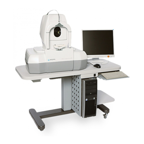
Optopol SOCT Copernicus User manual

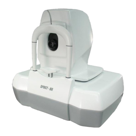
2
SOCT Copernicus User Manual Version 4.3.x rev. C
1. DESCRIPTION OF THE DEVICE............................................................................................................................. 5
2. TECHNICAL DATA ............................................................................................................................................... 5
2.1 SYMBOL INFORMATION ............................................................................................................................................. 6
2.2 RECOMMENDED SYSTEM REQUIREMENTS .................................................................................................................... 7
3. UNPACKING AND INSTALLATION........................................................................................................................ 8
3.1 UNPACKING SOCT COPERNICUS................................................................................................................................. 8
3.2 CONNECTING CABLES ............................................................................................................................................. 10
3.3 DEVICE CONNECTION.............................................................................................................................................. 12
3.4 FACTORY DEFAULT CALIBRATION AND CONFIGURATION................................................................................................... 13
3.5 SAFETY STANDARDS ............................................................................................................................................... 13
4. SOCT COPERNICUS SOFTWARE ........................................................................................................................ 15
4.1 RUNNING SOCT COPERNICUS APPLICATION ............................................................................................................... 15
4.2 SOCT COPERNICUS APPLICATION STRUCTURE.............................................................................................................. 15
5. MAIN WINDOW............................................................................................................................................... 16
5.1 PATIENT LIST VIEW. ................................................................................................................................................ 16
5.2 REGISTERING NEW PATIENTS.................................................................................................................................... 17
5.3 EDITING PATIENT'S PERSONAL DATA ........................................................................................................................... 18
5.4 UNREGISTERING PATIENTS....................................................................................................................................... 18
5.5 CURRENT EXAMINATION PANEL ................................................................................................................................ 18
5.6 FILTER................................................................................................................................................................. 19
5.7 CONNECTING SCANS CONNECTED TO THE WRONG PATIENT............................................................................................. 19
5.8 EXPORT EXAMINATION/S........................................................................................................................................ 20
5.8.1. Burn examinations on CD/DVD ............................................................................................................... 20
5.8.2. Export data files ...................................................................................................................................... 20
5.9 AUTOMATED ANALYSIS OF EXISTING EXAMINATIONS ...................................................................................................... 20
6. EXAMINATION WINDOW ................................................................................................................................. 21
6.1 DEVICE MOVEMENT CONTROLS ................................................................................................................................ 22
6.1.1 Joystick control.......................................................................................................................................... 23
6.1.2 Mouse Control .......................................................................................................................................... 23
6.2 SELECTION OF SCANNING PATTERN MODE.................................................................................................................. 24
6.3 CUSTOMIZING SCAN PARAMETERS ............................................................................................................................. 25
6.4 “VIEWFINDER”MODE............................................................................................................................................ 26
6.5 TOMOGRAM POSITIONING ....................................................................................................................................... 27
6.6 SCAN POSITIONING ................................................................................................................................................ 28
6.7 FOLLOW UP .......................................................................................................................................................... 28
7. CONDUCTING EXAMINATION........................................................................................................................... 29
7.1 CONDUCTING NEW EXAMINATION ............................................................................................................................. 29
7.2 DISC AREA EXAMINATION: ....................................................................................................................................... 30
7.3 ANTERIOR MEASUREMENT 1..................................................................................................................................... 31
7.4 EXTERNAL FIXATION................................................................................................................................................ 32
7.5 TIPS FOR EXAMINATION........................................................................................................................................... 33
8. RESULTS REVIEW WINDOW ............................................................................................................................. 35
8.1 TOMOGRAM TAB ................................................................................................................................................... 35
8.2 CONTROL PANEL FUNCTIONS .................................................................................................................................... 36
8.3 FUNDUS CAMERA IMAGE......................................................................................................................................... 37
8.4 IMAGE PANEL CONTROL........................................................................................................................................... 41
8.5 EDIT RECOGNITION OF LAYERS .................................................................................................................................. 42
8.6. RETINA THICKNESS MEASUREMENT........................................................................................................................... 43

3
SOCT Copernicus User Manual Version 4.3.x rev. C
8.7 DISTANCE MEASUREMENT .......................................................................................................................................44
8.8 CYSTS ANALYSIS .................................................................................................................................................... 45
8.8.1 Mark and edit a new cyst......................................................................................................................... 46
8.8.2 Editing marked cysts ................................................................................................................................. 48
8.9 3D DETECTION OF THE CYST..................................................................................................................................... 48
8.10 RETINA ANALYSIS CHARTS ...................................................................................................................................... 49
8.11 RPE CHARTS....................................................................................................................................................... 50
8.12 INFO TAB ........................................................................................................................................................... 50
8.13 ATTACHMENTS TAB............................................................................................................................................... 51
8.14 DIAGNOSIS TAB ................................................................................................................................................... 52
8.15 TOMOGRAM SELECTION WINDOW.......................................................................................................................... 52
8.16 PRINTOUT MANAGER .......................................................................................................................................... 53
8.16.1 Quick printout ......................................................................................................................................... 54
8.16.2 Generate report ...................................................................................................................................... 54
8.16.3 Customized printout................................................................................................................................ 55
8.16.4 Add to print manager method ................................................................................................................ 57
8.16.5 Generate report and add objects manually ............................................................................................ 57
8.16.6 Export to IRIS .......................................................................................................................................... 58
8.17 MENU ............................................................................................................................................................... 58
9. THREE DIMENSIONAL VISUALIZATION ............................................................................................................. 59
9.1 ADVANCED 3D MODE ............................................................................................................................................ 59
9.1.1 Displaying and highlighting selected retina layers ................................................................................... 61
9.1.2 Peeling layers............................................................................................................................................ 62
9.1.3 Tuning of the picture................................................................................................................................. 63
9.1.4 Display options. ........................................................................................................................................ 64
9.1.5 Surface mapping ....................................................................................................................................... 64
9.2 STANDARD 3D ...................................................................................................................................................... 66
9.2.1 Segmentation............................................................................................................................................ 68
9.2.2 Display options ......................................................................................................................................... 69
9.2.3 Surface mapping ....................................................................................................................................... 70
9.2.4 3D preview ................................................................................................................................................ 71
10. MACULA ANALYSIS ...........................................................................................................................................72
11. GLAUCOMA ANALYSIS ..................................................................................................................................... 75
11.1 FUNDUS RECONSTRUCTION/DEVIATION FROM NORMAL MAP...................................................................................... 75
11.2 TOMOGRAM PREVIEW .......................................................................................................................................... 76
11.3 RNFL THICKNESS MAP AND RNFL THICKNESS GRAPH.................................................................................................. 76
11.4 ONH (OPTICAL NERVE HEAD)DATA ....................................................................................................................... 77
11.5 CONTROL BUTTONS.............................................................................................................................................. 78
11.6 MANUAL DISC CONTOUR EDITION............................................................................................................................ 78
12. COMPARISON MODULE ................................................................................................................................... 80
12.1 TOMOGRAM TAB ............................................................................................................................................ 80
12.2 FOLLOW UP..................................................................................................................................................... 81
12.2.1 Retina Graphical Comparison ................................................................................................................. 81
12.2.2 Retina Numerical Comparison ................................................................................................................ 82
12.2.3 Glaucoma Numerical Analysis ................................................................................................................ 83
12.3 SYMMETRY ANALYSIS...................................................................................................................................... 84
12.3.1 Retina Numerical .................................................................................................................................... 84
12.3.2 Retina Graphical ..................................................................................................................................... 85
12.3.3 Glaucoma Symmetry Analysis................................................................................................................. 86
12.4 EXAMINATIONS CORRELATION ....................................................................................................................... 87
13. ANTERIOR ANALYSIS ........................................................................................................................................ 88
13.1 CORNEA ANALYSIS TAB .......................................................................................................................................... 89
4
SOCT Copernicus User Manual Version 4.3.x rev. C
13.2 ANGLE MEASUREMENT TOOL................................................................................................................................. 90
13.3 AOD MEASUREMENT .......................................................................................................................................... 90
14. SETUP WINDOW.............................................................................................................................................. 91
14.1 BACKUP ............................................................................................................................................................. 91
14.2 RECOVER ........................................................................................................................................................... 92
14.3 DATABASE SETUP ................................................................................................................................................. 93
14.4 PARAMETERS ...................................................................................................................................................... 94
14.5 USER ACCOUNTS.................................................................................................................................................. 95
14.5.1 Creating new user ................................................................................................................................... 95
14.6 JOYSTICK CONFIGURATION ..................................................................................................................................... 96
14.6.1. Joystick checking and calibration........................................................................................................... 96
15. MAINTENANCE AND CLEANING PROCEDURE....................................................................................................97
15.1 ROUTINE CLEANING ............................................................................................................................................. 97
15.1 SOFTWARE MAINTENANCE ACTIVITIES ...................................................................................................................... 98
15.3 HARD DISK DEFRAGMENTATION ............................................................................................................................. 98
15.4 ORDERING CONSUMABLES ..................................................................................................................................... 98
15.4 .1 Blown fuses exchange ............................................................................................................................ 99
16. ENVIRONMENTAL CONDITIONS ......................................................................................................................100
17. SERVICE ..........................................................................................................................................................100
18. UTILIZATION ...................................................................................................................................................100
19. DIMENSION AND WEIGHT ..............................................................................................................................100
20. FAQ - FREQUENTLY ASKED QUESTIONS ...........................................................................................................101
APPENDIX A CONFIGURATION OF NETWORK CONNECTION....................................................................................103
1. SOCT NETWORK.............................................................................................................................................103
1.1 SOCT SERVER CONFIGURATION PROCEDURE ............................................................................................................. 104
1.1.1 Sharing SOCT database folder on Windows XP ..................................................................................... 105
1.1.2 Sharing SOCT database folder on Windows 7........................................................................................ 106
1.2 CLIENT COMPUTER CONFIGURATION PROCEDURE....................................................................................................... 107
2. IRIS SERVER NETWORK ...................................................................................................................................109
2.0.1 Upload on server..................................................................................................................................... 109
2.0.2 Download from server ............................................................................................................................ 110
2.1 CLIENT COMPUTER CONFIGURATION PROCEDURE: ...................................................................................................... 111
2.2 COPERNICUS IRIS SERVER CONFIGURATION ...............................................................................................................112
2.2.1 Introduction ............................................................................................................................................ 112
2.2.2 Requirements.......................................................................................................................................... 112
2.3 COPERNICUS SERVER IRIS INSTALLATION. ................................................................................................................. 112
2.4 MODULE CONFIGURATION.....................................................................................................................................115
2.5 FAQ ................................................................................................................................................................. 117
APPENDIX B .............................................................................................................................................................121
PARK POSITIONING..................................................................................................................................................... 121
APPENDIX C .............................................................................................................................................................122
EMC INFORMATION................................................................................................................................................... 122

5
SOCT Copernicus User Manual Version 4.3.x rev. C
1. DESCRIPTION OF THE DEVICE
This manual explains the details of the function and use method to make a good use of the
SOCT system. Before using the device, carefully read this manual to ensure that you operate it
efficiently and safely. Always keep this manual at hand to make a good use of it.
SOCT Copernicus uses Spectral domain Optical Coherence Tomography method to obtain 3-
dimensional cross-section images of the retina.
SOCT Copernicus is an optical coherence tomography system indicated for the in vivo imaging
and measurement of the retina, retina nerve fiber layer, and optic nerve head as an aid in the
diagnosis and management of posterior segment diseases The device produces a light beam,
which is focused on the human retina. The light that reflects from internal structures of an eye
is then interferometrically analyzed by the device. The raw data is processed by a computer to
obtain images of eye cross-section. The SOCT Copernicus contains features that include:
Retina Thickness, Optical Nerve Head, Retinal Nerve Fiber Layer, Angle assessment, Cornea
measurement1.
2. TECHNICAL DATA
Signal source Super Luminescent Diode (SLED), 830 nm
Optical power 750 µW
Signal analysis Spectral domain Optical Coherence Tomography
Scanning speed 25’000 measurements per second
Scanning programs Single B-scan
3D visualization
Asterisk
Animation scan (selected number of B-scans in the
same place at a retina)
Circle scan
Axial resolution 6 µm
Transversal resolution ideal 12 µm
typical 18 µm
Scan width 4 –10 mm
Scan depth >2.5 mm
Power supply 100-240 V 50/60 Hz,
Power consumption 150 VA
Fuse ratings M 3.15 A L 250V
Multiple socket-outlet max. load 500 V

6
SOCT Copernicus User Manual Version 4.3.x rev. C
2.1 Symbol information
CAUTION
Follow operating instruction
WARNING –Dangerous voltage
General warning sign
Indicates a fuse is present near this symbol
On / Off
Type B Applied Parts
Date of manufacture
Manufacturer
Electrical and Electronic Equipment waste. Do not throw the product away with a
normal household waste at the end of its life.
Sign conformity with essential requirements –The Medical Device Directive
93/42/EEC
Class 1 Laser Device
Caution: Federal law restricts this device to sale by or on the order of a physician or practitioner

7
SOCT Copernicus User Manual Version 4.3.x rev. C
2.2 Recommended system requirements
Processor: Intel® Core™2 Quad Q6600
RAM: XP & Win7 32bit - 4 GB
Operating system: Windows XP Professional, Windows 7 Professional
HDD: Minimum 500GB (15MB per measurement)
CD/DVD writer
Video card: OpenGL support, ATI Radeon 4850 512 MB or faster
1024 X 768 resolution
Communication: 1 available USB port
Extension slots: 2 available PCI slots
1 available PCI Express (x16)

8
SOCT Copernicus User Manual Version 4.3.x rev. C
3. UNPACKING AND INSTALLATION
NOTICE!: Check for any damage to the package. Every transportation box is equipped with the
shockwatches. If any shockwatch is broken (red indicator) please contact OPTOPOL Technology S.A. and lodge
the complaint to the carrier.
SOCT Copernicus set consists of following components:
1. SOCT device with CL cable,
2. RS232 communication cable,
3. Coaxial synchronization/video cable,
4. PC Computer with preinstalled software,
5. Computer accessories
6. Power supply cables and computer accessories.
3.1 Unpacking SOCT Copernicus
This section describes how to unpack the device shipped from a factory. The SOCT Copernicus is shipped in a
special box, which protects it from mechanical damages during transport. The box has got four latches shown
in detail in pictures below.
Closed latch
Step 1
Step 2
Latch is opened

9
SOCT Copernicus User Manual Version 4.3.x rev. C
Remove the cover by lifting it up gently. The SOCT ’s four legs are locked at two metal rails by clamps. There
are only two removable clamps at a side. First remove screws from the clamps and then remove metal
holders. This operation is shown in a figure below.
Figures below show how to unpack SOCT Copernicus from this box.
Now shift SOCT Copernicus to the left and then lift it up. Put the SOCT on the flat stable table.
Important!
Always let the device reach room temperature before it is powered up but not less than 1 hour after
unpacking. This is particularly important if the device was exposed to temperature extremes. Always
operate the device within operating ranges of temperature and humidity (see chapter 16).
Transport position of the SOCT Copernicus is to be set manually. Head maximum to the left, to the back
and lens down. Then protect handle will fit correctly.
After unpacking, one should check the whole set for any mechanical damages,
cables damages, etc. In case any damage is found, don't connect the device
and contact your local distributor.

10
SOCT Copernicus User Manual Version 4.3.x rev. C
3.2 Connecting cables
To connect the SOCT Copernicus to a computer, you need five cables shipped with the device:
Camera link cable –connected to SOCT Copernicus (not detachable),
CL1
RS232 cable
Video/synchro cable connected with one plug,
Video (to PC) Synchro (BNC to BNC splitter) Video/Synchro to SOCT Copernicus
Video-synchro cables are merged together.
Adapter cable. This is a short cable with 4 BNC plugs and VHDC plug on the other side.
Synchro cable shown above should be connected to BNC splitter (T0 port)
All sockets and plugs are different so it is not possible to connect plugs improperly.
BNC Splitter to
Synchro cable
BNC Splitter to
computer

11
SOCT Copernicus User Manual Version 4.3.x rev. C
Figure below shows rear panel view of SOCT Copernicus.
RS232, video and synchro cables are merged together as shown below.
First connect all signal cables described above and after that check the connections once again. In the next
step connect power supply cables.
NOTE: Regarding EMC (Electro-magnetic compatibility) standards all signal cables have to be put together.
Picture belowshows how to connect all cables to the computer.
Power switch
Video / Synchro
RS232
Power connector
Fuses socket
Camera link cable
Video - Computer
RS232 -SOCT
Video / Synchro - SOCT
RS232 - Computer
Synchro –BNC splitter
Power supply connector
Keyboard and mouse PS/2
RS232
Monitor
USB (printer, joystick,
keyboard and mouse with
USB plug)
BNC splitter
Video input
Camera link

12
SOCT Copernicus User Manual Version 4.3.x rev. C
3.3 Device connection
The SOCT Copernicus is connected to the PC using RS232 and Video/Synchro cables.
The SOCT Copernicus must be directly plugged into the mains with protective earth. Connect
the PC, printer and monitor into the multiple portable socket-outlet, which is directly
connected to the Separating Transformer. By connecting the devices to the Separating
Transformer leakage current is reduced to a level which is in line with the IEC standard. The
Separating Transformer is connected directly to the mains with protective earth pin.
Dedicated table SE-275 has built in the isolator transformer. When the SOCT system is installed on the
table SE-275, only one cable from to the set (table + OCT system) goes to the main with protective
earth pin. The device has to be connected to the main below the top of the table. Elements of
computers set have to be connected to multiple sockets in the metal box.
Applied part:
forehead support
Locally mains look
different
Applied part:
chin rest support
Socket for SOCT
Multiple socket for
the computer set

13
SOCT Copernicus User Manual Version 4.3.x rev. C
3.4 Factory default calibration and configuration
The system is delivered fully installed and configured. No user installation or configuration is
needed.
The assembly of ME Systems and modifications during actual service life shall be evaluated based on
the requirements of IEC 60601-1:2005 standard.
3.5 Safety standards
Before first use the device operator should be trained how to use the system efficiently and safely.
The SOCT Copernicus system complies with all requirements of the directive 93/42/EEC (MDD -
Medical Devices Directive).
The SOCT Copernicus is type B applied parts (chin rest support and forehead support ) and class I
protection against electric shock.
Usually SOCT Copernicus is a part of larger Medical System, which consists of many other medical
and non- medical devices. Medical system in general and all its components have to fulfill the
requirements of IEC 60601-1:2005 standard.
In order to comply with the IEC 60601-1:2005 standard all non Medical Devices must be connected
to the Separating Transformer which is supplied with the SOCT Copernicus. By connecting the
devices to the Separating Transformer leakage current is reduced to a level which is in line with
the IEC standard.
The Separating Transformer fulfills requirements of IEC 60601-1:2005 standard for medical
electrical system.
The Separating Transformer supplies the power for non medical devices connected to electric not
grounded mains in room.
The Separating Transformer can be installed in patient environment in accordance with IEC-60601-
1:2005 standard.
SOCT Copernicus system can be connected only to power supply socket equipped with
properly connected grounding pin.
Please note that only the PC, monitor and printer have to be connected to the Isolating
Transformer. Connecting non medical devices in other way than in diagram above can lead to
electric shock or damage the devices.
It is strictly forbidden to connect any non medical or medical devices which are not included
within the SOCT Copernicus system to the Separating Transformer e.g. lamp, vacuum cleaner
etc.
The SOCT Copernicus must not be connected to the transformer, but directly to the main outlet or
to the dedicated outlet in the table.

14
SOCT Copernicus User Manual Version 4.3.x rev. C
SOCT Copernicus is connected to computer using USB cable. This cable is electrically separated
using optocouplers. It provides additional safety, when computer and SOCT Copernicus device are
connected to two different power supply sockets with different ground potentials. Video signal
and synchronization signal are transferred to computer using coaxial cables, which are electrically
separated from SOCT Copernicus device providing even more safe solution.
No user serviceable parts are inside SOCT Copernicus device. Light source is included inside the
device. Removing the covers can be done only by authorized personnel.
The maximum power of light radiation available outside covers is less than 750 microwatts
providing safe operation of the device.
Objective lens is output of light.
SOCT Copernicus has been classified as CLASS 1 LASER DEVICE
Important !
1) If the whole Medical System has been installed by Manufacturer of SOCT Copernicus
or Authorized Personnel , the manufacturer guarantees correct installation and
compliance with all required standards and directives,
2) In case installation was made not by Manufacturer or Authorized Personnel, the
manufacturer of SOCT Copernicus takes NO responsibility for any problems or risks
that could be created by incorrect connection and violation of safety standards,
3) Understanding and following up of sections 5, 6, 7, 8, 9 of this manual as well as
computer experience are sufficient level of training of user the SOCT Copernicus
device.
4) Manufacturer of SOCT Copernicus takes no responsibility for incorrect medical
diagnosis of results and takes no responsibility for the consequences of such incorrect
medical diagnosis.
Warning !
To avoid risk of electric shock, this equipment must only be connected
to a supply mains with protective earth. Ignoring safety rules can lead to
accidents.
1) If SOCT Copernicus + and the whole Medical System have been installed by the
Manufacturer or Authorized Personnel, the Manufacturer guarantees the proper
installation and compliance with MDD 93/42 EEC rules,
2) Any computer system or device attached to SOCT Copernicus must be MDD compliant
or be plugged only to Separating Transformer. Devices which are not related with
patient examination (e.g. lamp, fan) cannot be connected to Separating Transformer,
3) Multiple portable socket-outlets shall not be placed on the floor.
4) Any Additional Multiple Socket-Outlet or extension cord shall not be connected to the
ME System.
Warning !
All activities that demand removing main body housing may be performed by Manufacturer or
Authorized Personnel trained by Manufacturer only.
Ignoring or disregarding the statements above may lead to danger of death or serious injury.

15
SOCT Copernicus User Manual Version 4.3.x rev. C
4. SOCT Copernicus SOFTWARE
4.1 Running SOCT Copernicus application
After the Windows operating system is started and initialized, it is possible to run SOCT Copernicus
application. Click “Start” button and go to SOCT group. Click SOCT icon and the application will be
loaded and activated.
IMPORTANT: Always TURN ON the computer first and then TURN ON device.
4.2 SOCT Copernicus application structure
The application has been created to make using as easy for the operator as possible. All the buttons
are big and located ergonomically. The whole idea of software makes the usage very effective.
SOCT Copernicus software is divided into four different modules which can be easily accessed by
their tabs:
Patients It appears just after the system is started. It enables to easily handle
patients’ database,
Examination It contains all controls to perform a new examination,
Results review It enables to preview previously taken examinations, quantitative
analysis, compare results symmetrically or progressively.
Setup It enables to set all the parameters of the system. Also backup and
restore of the database can be done from this level.
Patients window
Results review window
Examination
window
Setup window

16
SOCT Copernicus User Manual Version 4.3.x rev. C
5. MAIN WINDOW
The patient tab will appear on the main window after the SOCT Copernicus HR application is started.
Patient tab enables the user to easily manage patients’ database:
-add new patients to the database,
-delete patients from the database,
-edit patients’ personal data,
-enter remarks regarding patients,
-import/exporting data.
All the controls of main window are shown on picture below with short description.
5.1 Patient list view.
In order to find a patient from the list you can enter first few letters of his Last name in fast search
edit box. Computer will show the closest matching patient. Default patients are sorted in the list by
Last name . Click the Ref. No. header to sort by ID number. It is also possible to sort by First name
and Date of Birth.
[Fast search] mechanism: use this field to quickly find patient on the list.
Sort the patients
according to selected
column .
Tomogram preview
Fundus reconstruction
preview
Fast search
mechanism
Info Card
Device ID
Choose the modules
Click to enter Setup
window
Patient database
management
Patient data
Current examination
info
Examination filter
Enter first letters of
patient's last name and
computer will mark the
closest match

17
SOCT Copernicus User Manual Version 4.3.x rev. C
5.2 Registering new patients
In order to register new patient, click [New patient]
button in main window. Patient registration window
will show in the right upper corner. Patient's first
name, second name, and date of birth have to be
entered in proper fields.
It is possible to add to patient’s record information
about group classifications. Operator can create own
groups, e.g. diseases AMD, CRV, MH, LMH. To create a new group, type its name into the box.
System automatically adds this group into filters. One patient can belong to one or two groups. Each
eye can be classified as member of one group.
Operator can store also refraction value in patients record. This value will be transferred into
measurement mode.
FILLING THESE FIELDS DOES NOT RELEASE FROM CORRECTION OF FOCUS IN MEASURAMENT
MODE.
When all the data are entered, click “Enter” button to confirm registration. The system will check if
the entered data are correct. If not, it will ask to correct the data.
Important!
Make sure you have entered correct patient name and date of birth. It will prevent you from data
loss and will enable you to keep the database in good condition without having “dead souls” in
patients list.
If computer notices that the patient being entered is already registered in the database, a warning
message will appear.
If computer realizes, that the name of currently entered patient is already in database but the date
of birth is different, it will display a warning message.
“Last name”, “First name” and “Date of birth” fields are
obligatory fields and have to be properly filled. Other fields are
optional and can be left empty.

18
SOCT Copernicus User Manual Version 4.3.x rev. C
It means that there is a suspicion, that the patient already exists, but the date of birth was entered
incorrectly. The operator should make sure the data is correct and can decide whether to register
the patient or cancel registration.
5.3 Editing patient's personal data
In order to edit currently selected patient's personal data, click [Edit] button in main window. The
fields are exactly the same as in [New patient] window. After patient's data have been changed, click
[Enter] button. Once again computer will check the data and display a warning message if entered
data are incorrect. Then the computer will do the same checking as during registering new patient.
5.4 Unregistering patients
In order to unregister currently selected patient, click [Delete] button in main window. A warning
message will be displayed.
After pressing 'Yes' button the second confirmation window will be displayed. If the answer is 'Yes'
again, the patient and all examination results will be deleted.
5.5 Current examination panel
Current examination panel contains information regarding currently selected examination. The
image of this panel is shown below.
Click to delete
selected
examination
examination
Fundus image
Thumbnail of
scanned image
List of all patient’s
examinations
Click to Import
examination
examination
Click to Export selected
examination
examination
Once the patient is deleted, it's impossible to recover the deleted
data. Please make sure you are deleting proper patient.
Click to start analysing
examinations
Analysis status

19
SOCT Copernicus User Manual Version 4.3.x rev. C
Examinations window –shows all examinations made for the selected patient.
Here are information about date and time of examination, identification of the eye, chosen fixation
target, scan program, scan width, scan dimension column shows scan dimensions in number of A-
scans and B-scans.
Fundus image –shows fundus view at the start of examination or reconstruction of fundus
in 3D mode,
Thumbnail of scanned image shows a preview of a tomogram from the examination.
It is possible to move examination from one patient to another. Click right button and choose “Cut
examination”then choose destination patient and paste to proper patient.
5.6 Filter
The filter window helps to easily find examinations in the database. It is possible to filter
examinations for selected patient or to filter examinations with reference to all existing patients. In
order to apply filter mark [Apply filter to patients] checkbox.
User can filter examinations by:
-Date: Today’s or specific Date checkbox. In the list of all examinations
you will see only that which has been made today (or on specified
date) - all others will be hidden,
-Eye: If you want to hide examinations of Left or Right eye, unmark
check box labeled Left eye or Right eye,
-Scan program: Animation, Asterisk, 3-D, single B-scan etc –only the
selected type examinations will be visible,
-Analysis: Retina, Disc, Anterior - only the selected type’s
examinations will be visible,
-Group - Groups are made by operator on patient data editing
window and can be used to filter patients,
-Gender - Male, Female, Not defined –only patients of selected
gender will be displayed in the list.
Use [Apply] button to enable filtering.
Use [Clear filter] button to reset the filter settings and disable filtering.
5.7 Connecting scans connected to the wrong patient
The user has the option of moving examinations from an incorrect patient association, to the
correct patient association.
1. Select the Examination on examination list > examination you wish to move
2. Press the right mouse button on and press [Cut examination]
3. Select patient on the list where you wish to move examination
4. Press the right mouse button and choose [Paste examination].

20
SOCT Copernicus User Manual Version 4.3.x rev. C
5.8 Export examination/s
The SOCT Copernicus offers the ability to export examinations data. Thanks to the option patients
can receive CD disc with reports, movies, tomograms in format which can be easily reviewed by
another specialist.
5.8.1. Burn examinations on CD/DVD
Burning/Saving steps
1. Select the Patient on patient list > Patient you wish to burn examination results
2. Press the right mouse button on and press [Burn on CD\DVD]
3. Select examinations on the list.
4. Define exported data format. Burning disc will include chosen type of data (tomograms, reports,
movies, .oct data).
Note: .oct format of data can be reviewed only by SOCT Copernicus software.
5. Choose the drive. If you choose HDD, software will save data on it.
6. Press the [Burn/Save] button.
5.8.2. Export data files
Export steps
1. Select the Examination/s on examination list > examination/s you wish to export
2. Hold the Ctrl button on the keyboard and choose all exams you wish to export
3. Press [Export examination]
4. Choose a destination folder and press [OK] button.
5.9 Automated analysis of existing examinations
On the examination list the last column shows analysis status. The SOCT Copernicus application
enables automatic calculation collected .oct exams. Operator can choose one from two options.
-Not recognized examinations –the software calculate only examinations which have not
been analysed.
-All examination –this function recalculate all examinations from the database.
Note: By choosing this options software will delete all comments, manual measurement and
layers recognition corrections. It is recommended to use this option after upgrading the software
into newer version.
Other manuals for SOCT Copernicus
1
Table of contents
Other Optopol Medical Equipment manuals

Optopol
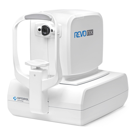
Optopol REVO nx User manual

Optopol
Optopol SOCT Copernicus REVO Quick start guide

Optopol
Optopol SOCT Copernicus + User manual

Optopol
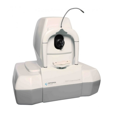
Optopol SOCT Copernicus HR User manual

Optopol
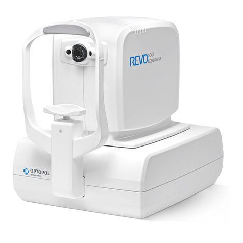
Optopol SOCT Copernicus REVO User manual

Optopol
Optopol SOCT Copernicus User manual

Optopol
Optopol SOCT Copernicus REVO User manual