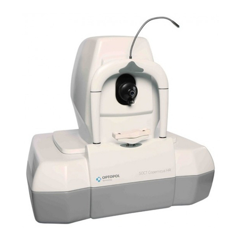
Optopol SOCT Copernicus User manual

SOCT Copernicus / SPOCT - Service Manual
2
CONTENTS
1. Introduction ......................................................................................................................... 5
2. Contact to Optopol Technology Sp. z o.o................................................................................ 5
3. Warnings and Cautions ......................................................................................................... 6
4. Safety Standards................................................................................................................... 7
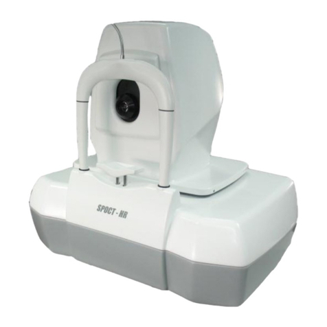
5. Device Overview................................................................................................................... 9
6. Technical Data ...................................................................................................................... 9
7. Environmental Conditions ................................................................................................... 10
8. Unpacking and Installation.................................................................................................. 11
8.1 Unpacking SOCT Copernicus ................................................................................................. 11
8.2 Connecting cables.................................................................................................................. 13
8.3 Device connection ................................................................................................................. 15
9. PC installation..................................................................................................................... 16
9.1 System requirements ............................................................................................................ 16
9.2 NI Frame Grabber card and WinFast card installation.......................................................... 17
9.3 Drivers installation ................................................................................................................ 18
9.3.1 NI Vision Acquisition Software installation ................................................................... 18
9.3.2 USB HUB drivers installation ......................................................................................... 27
9.3.3 WinFast TV Card drivers installation ............................................................................ 29
9.3.4 Microsoft Visual C++ Redistributable installation ......................................................... 32
9.4 SOCT Software installation.................................................................................................... 34
10. Troubleshooting ................................................................................................................... 38
10.1 Mechanical ............................................................................................................................ 38
10.2 Electronic troubleshooting.................................................................................................... 39
10.3 Optical troubleshooting ........................................................................................................ 43
11. Opening and closing the device ............................................................................................. 47
11.1 Opening cover ....................................................................................................................... 47
11.2 Closing the cover ................................................................................................................... 56
12. Movement modules.............................................................................................................. 66
12.1 Chinrest module ........................................................................................................................ 66
12.2 Chinrest modules produced after 09.2008 ............................................................................... 73
12.3 Backward and forward movement........................................................................................ 76

SOCT Copernicus / SPOCT - Service Manual
3
12.4 Left and right movement....................................................................................................... 82
12.5 Up and down movement........................................................................................................... 87
12.6 Replacing up and down movement microswitches .................................................................. 90
13. Electronic boards .................................................................................................................. 92
13.1. Block diagram of the device ..................................................................................................... 92
13.2. Necessary tools for replacing electronics components ........................................................... 94
13.3. Replacing power supply board (150-521 –SUPERLUM DIODE); 150-522 (EXALOS DIODE) .... 95
13.4. CPU (150-505) and Control movement board (150-515)......................................................... 99
13.5. Replacing of servomechanism driver 150-536....................................................................... 104
13.6. Replacing of drivers of spectrometer’s servomechanisms (150-536).................................... 105
13.7. Checking the SLED diode EXALOS........................................................................................... 108
13.8. Checking and adjusting the Superlum diode.......................................................................... 110
13.9. Replacing fuses on the rear panel .......................................................................................... 113
13.10. Rear panel ............................................................................................................................ 115
13.11. Programming the CPU.......................................................................................................... 116
13.12. Replacing of Transitional board (150-530)........................................................................... 121
13.13 XY scanner cables exchange................................................................................................ 127
13.13.1 Separation of cable bunch before exchange X –scanner or Y –scanner cable .......... 127
13.13.2 X –scanner cable exchange......................................................................................... 129
13.13.3 Y –scanner cable exchange......................................................................................... 133
13.13.4 Connection of cable bunch after exchange X –scanner or Y –scanner cable. ........... 136
14. Optics..................................................................................................................................138
14.1 Manual spectrometer.............................................................................................................. 138
14.2 Autospectrometer .................................................................................................................. 142
14.3 No signal in skantest program................................................................................................. 143
14.4 Defocusing of spectrometer (too wide peak)......................................................................... 145
14.5 Too low spectrum on skantest ................................................................................................ 148
14.6 Too high spectrum on skantest ............................................................................................... 150
14.7 Checking and adjusting power on objective lane.................................................................... 151
14.8 Setting fixation point to the centre of the cross ..................................................................... 155
14.9 Checking and adjusting the polarization................................................................................. 164
14.10. Checking, adjusting and exchange of scanners.................................................................... 169
14.10.1 Exchanging of scanner Y ............................................................................................. 171
SOCT Copernicus / SPOCT - Service Manual
4
14.10.2 Exchange scanner X..................................................................................................... 175
14.10.3 Correcting scanner setup ............................................................................................ 180
14.11 Cleaning optics ...................................................................................................................... 184
14.12 Regulation of filter on reference lane................................................................................... 189
14.13 Checking of SLED output power, checking attenuator.......................................................... 192
14.14 Crossing the spectrometer.................................................................................................... 197
14.14.1 Manual crossing of spectrometer ............................................................................... 197
14.14.2 Automatic crossing of spectrometer........................................................................... 203
14.15 Focusing the spectrometer ................................................................................................... 205
14.16. Checking the stability of the spectrometer.......................................................................... 206
14.17. Eliminating the improper Cross lines shape......................................................................... 208
15. FAQ ....................................................................................................................................209
16. Spare parts list...................................................................................................................222
17. Service tools ........................................................................................................................234

SOCT Copernicus / SPOCT - Service Manual
5
1. Introduction
This Service manual contains technical information about SOCT Copernicus, troubleshooting of SOCT
Copernicus, parts and modules exchange procedures, description of calibration procedure. The
information provided in this document has been prepared for trained service technicians.
2. Contact to Optopol Technology Sp. z o.o.
In case of any problems or doubts concerning technical procedures or other information
contained in this manual, please contact one of the following:
Customer Support:
Sales
Tel: +48 32 67 09 173
Technical Support:
Service department
Tel: +48 32 67 09 173 ext. 230
service@optopol.com.pl
For online support use a program: TeamViewer (Optopol Technology Service Department will
provide distributors with Customer module).
In case the distributor decides to send back the device to Optopol Technology Sp. z o.o. , RMA form

SOCT Copernicus / SPOCT - Service Manual
6
3. Warnings and Cautions
Optopol Technology is not responsible for the safety and reliability of this instrument when:
Assembly, disassembly, repair or modification is made by unauthorized dealers or
persons.
Instrument is not used in accordance with its User’s Manual.
WARNING - An instruction that draws attention to the risk of injury or death.
CAUTION - An instruction that draws attention to the risk of damage to the product.
WARNING: DO NOT PERFORM ANY REPAIRS WITH DEVICE PLUGED INTO POWER SUPPLY.
WARNING: ALL ACTIVITIES THAT DEMAND REMOVING BODY HOUSING MAY BE PERFORMED
BY QUALIFIED PERSONEL ONLY.
CAUTION: DO NOT USE SOLVENTS OR STRONG CLEANING SOLUTIONS ON ANY PART OF THIS
INSTRUMENT OR DAMAGE TO THE UNIT MAY OCCUR.
CAUTION: THIS INSTRUMENT MUST BE PLUGGED INTO AN OUTLET WITH AN EARTH GROUND
THAT IS CONNECTED TO THE RECEPTACLE OR DAMAGE TO THE UNIT MAY OCCUR.
DO NOT DISABLE OR REMOVE THE GROUND PIN.
CAUTION: MAKE SURE THAT THE VOLTAGE APPLIED TO THE UNIT IS THE SAME AS THE
VOLTAGE THAT IS GIVEN ON THE DATA PLATE NEXT TO THE INPUT CORD
RECEPTACLE OR DAMAGE TO THE UNIT MAY OCCUR.

SOCT Copernicus / SPOCT - Service Manual
7
4. Safety Standards
The SOCT Copernicus system complies with all requirements of the directive 93/42/EEC (MDD -
Medical Devices Directive).
The SOCT Copernicus is Type B, Class I protection.
Usually SOCT Copernicus is a part of larger Medical System, which consists of many other medical
and non- medical devices. Medical system in general and all its components have to fulfil
requirements of IEC-60601 norm.
In order to comply with the IEC-60601 norm all non Medical Devices must be connected to the
Separating Transformer which is supplied with the SOCT Copernicus. By connecting the devices to
the Separating Transformer leakage current is reduced to a level which is in line with the IEC norm.
The Separating Transformer fulfils requirements of IEC-60601-1 norm for medical devices which
has not application part.
The Separating Transformer supply the power for non medical devices connected to electric not
grounded mains in room.
The Separating Transformer can be installed in patient environment in accordance with
IEC-60601-1 norm.
SOCT Copernicus is connected to computer using RS232 cable. This cable is electrically separated
using optocouplers. It provides additional safety, when computer and SOCT Copernicus device are
connected to two different power supply sockets with different ground potentials. Video signal
and synchronization signal are transferred to computer using coaxial cables, which are electrically
separated from SOCT Copernicus device providing even more safe solution.
No user serviceable parts inside SOCT Copernicus device. Light source is included inside device.
Removing of covers can be done only by authorized personnel.
The maximum power of light radiation available outside covers is
less than 750 (+3% -0,5%) microwatts providing safe operation of the device.
Objective lens is output of light.
SOCT Copernicus has been classified as CLASS 1 LASER DEVICE
SOCT Copernicus/SPOCT system can be connected only to power supply socket equipped with
properly connected grounding pin.
Please note that only the PC, monitor and printer are to be connected to the Isolating Transformer.
Connecting non medical devices in other way than in diagram on page 13 can lead to electric shock
or damage the devices.
Prohibit connect any non medical or medical devices which are not including with SOCT
Copernicus system to the Separating Transformer e.g. lamp, vacuum cleaner etc.
The SOCT Copernicus must not be connected to the transformer, but directly to the mains socket.

SOCT Copernicus / SPOCT - Service Manual
8
Important !
1) If the whole Medical System has been installed by Manufacturer of SOCT Copernicus,
the manufacturer guarantees correct installation and compliance with all required
norms and directives.
2) In case when installation was made not by Manufacturer, Manufacturer of SOCT
Copernicus takes NO responsibility for any problems or risks that could be created by
incorrect connection and violation of safety standards.
3) Manufacturer of SOCT Copernicus takes no responsibility for incorrect medical
diagnose of results and takes no responsibility for the consequences of such incorrect
medical diagnosis.
4) Storage at excessively low temperatures, such as outdoors in winter , may result in a
delay during installation and subsequent shortening of the time available for training
by the Optopol Customer Service representative.
Warning !
Ignoring safety rules can lead to accidents.
1) If SOCT Copernicus and the whole Medical System have been installed by the
Manufacturer, the Manufacturer guarantees the proper installation and compliance
with MDD 93/42 EEC rules. It is customers’ responsibility to prepare the site.
2) Any computer system or device attached to SOCT Copernicus must be MDD compliant
or be plugged only to Separating Transformer. Devices which are not related with
patient examination (e.g. lamp, fan) cannot be connected to Separating Transformer.
3) Multiple portable socket-outlets shall not be placed on the floor.
Warning !
All activities that demand removing main body housing may be performed by qualified
personnel only.
Ignoring or disregarding the statements above may lead to danger of death or serious injury.

SOCT Copernicus / SPOCT - Service Manual
9
5. Device Overview
6. Technical Data
Signal source: Super Luminescent Diode (SLED), 840 nm
Optical power: 750 microwatts (+3% -0.5%)
Signal analysis: Spectral domain Optical Coherence Tomography
Scanning speed: 25’000 measurements per second
Scanning programs: single B-scan
3D
Asterisk
Animation scan (selected number of B-scans in the same place at a
retina)
Axial resolution: 6um in tissue
Transversal resolution:
- ideal 12 um
- typical18 um
Scan width: 4 –10 mm
Scan depth: 3.5 mm
Power supply: 230/115 V 50/60 Hz or 110 V 50/60 Hz
Power consumption: 150 VA
Fuse ratings: 3.15 A 250V
Multiple portable socket-outlet:
- max. load 500 VA
SOCT Copernicus uses spectral domain optical coherence tomography method to obtain
3-dimensional cross-section images of a human retina. The device produces a laser beam,
which is focused on a human retina. The light that reflects from internal structures of the
retina is then interferometrically analyzed by the device. The raw data is processed by a
computer to obtain images of retina cross-section.

SOCT Copernicus / SPOCT - Service Manual
10
7. Environmental Conditions
Operation:
Temperature in the SOCT room should ideally remain between 65 ºto 80 ºF, (18-27 ºC) both for
patient comfort and for optimum operation of the unit. Patients may feel discomfort when
temperature in the room is excessively high. Maximum operating temperature is 104 ºF (40 ºC) is
allowed.
Transport/storage:
Temperature: +0 º - +55 º C
Humidity: 20% - 90%
Atmospheric pressure: 600 hPa - 1200 hPa

SOCT Copernicus / SPOCT - Service Manual
11
8. Unpacking and Installation
NOTICE: Every transportation box is equipped with schockwatches. If any of the shockwatches is
broken, please contact Optopol and lodge the complaint to the carrier.
1. SOCT Copernicus set consists of the following components:
2. SOCT device with CL cable.
3. RS232 communication cable.
4. Coaxial synchronization/video cable.
5. PC Computer with preinstalled software.
6. The power supply cables and computer accessories.
8.1 Unpacking SOCT Copernicus
This section describes ho to unpack the device shipped from a factory. The SOCT Copernicus is
shipped in a special box, which protects it from mechanical damages during transport. Figures below
show how to unpack SOCT from this box. The box has got four latches shown in detail in pictures
below.
Closed latch
Step 1
Step 2
Latch is opened

SOCT Copernicus / SPOCT - Service Manual
12
Now one can remove the cover by lifting it up gently. The SOCT’s Copernicus four legs are locked at
two metal rails by clamps. There are only two removable clamps at a side. First remove screws from
the clamps and then remove metal holders. This operation is shown in a figure below.
Now shift SOCT Copernicus to the left and then lift it up. Put the SOCT on the flat stable
table.
Important!
It's strongly recommended to wait at least one hour before turning the device on for the first time
after delivery. It's mostly important in case where the delivery was made during low outside
temperatures or high humidity.
After unpacking one should check the whole set for any mechanical damages, cables
damages, etc. In case any damage is found, don't connect the device and contact your
local distributor.

SOCT Copernicus / SPOCT - Service Manual
13
8.2 Connecting cables
To connect the SOCT Copernicus to a computer, you need five cables shipped with the device:
1. Camera link cable –connected to Copernicus (not detachable).
2. RS232 cable.
3. Video/synchro cable connected with one plug.
Video (to PC) Synchro (BNC to PC) Video/Synchro to SOCT
4. Adapter cable. This is a short cable with 4 BNC plugs and VHDC plug on the other side.
Synchro cable shown above should be connected to BNC splitter
(T0 port).
BNC Splitter to
Synchro cable
BNC Splitter to
computer

SOCT Copernicus / SPOCT - Service Manual
14
All sockets and plugs are different, so it is not possible to connect plugs improperly. Figure below
shows rear panel view of SOCT.
RS232, video and synchro cables are merged together as shown below.
First connect all signal cables described above and after that check the connections once again. In the
next step connect power supply cables. Picture on the next page shows how to connect all cables to
the computer.
Power switch
Video / Synchro
RS232
Power connector
Fuses socket
Video - Computer
RS232 -SOCT
Video / Synchro - SOCT
RS232 - Computer
Synchro –BNC splitter
Camera link cable
Power supply connector
Keyboard and mouse PS/2
RS232
Monitor
USB (printer, joystick,
keyboard and mouse with
USB plug)
BNC splitter
Video input
Camera link
Voltage switch

SOCT Copernicus / SPOCT - Service Manual
15
8.3 Device connection
The SOCT is connected to the PC using RS232 and Video/Synchro cables.
The SOCT must be directly plugged into the mains. Connect the PC, printer and monitor into the
multiple portable socket-outlet, which is directly connected to the Separating Transformer. The
transformer reduces power emission loss from the PC. The Separating Transformer is connected
directly to the mains.

SOCT Copernicus / SPOCT - Service Manual
16
9. PC installation
9.1 System requirements
(Starting on day 22.09.2010)
In order to prepare computer for use with SOCT Copernicus you need:
PC computer with operating system installed.
Minimum system requirements:
- Processor: Intel® Xeon W3520 2.66 8MB/1066 QC CPU
- RAM: HP 4 GB (2x2GB) DDR3 –1333 ECC RAM
- Operating system: Windows XP Professional, Windows 7 32-bit
- HDD: 2 x HP 1.5 TB SATA 7200 HDD (RAID)
- CD/DVD writer HP 16X DVDRW Drive
- Video card: 1024 X 768 resolution
24 bits color depth
512 MB DDR3
OpenGL support (ASUS EAH 5770 CUcore1024 MB)
- Communication: 1 available USB port
- Extension slots 2 available PCI slots
2 available PCI Express (x16)
National Instruments IMAQ PCI-1428 image acquisition card (supplied with SOCT device)
Frame grabbing card (supplied with SOCT device)
SOCT Copernicus Installation CD (supplied with SOCT device)
National Instruments installation CD –Disk 1 and 2 (supplied with SOCT device)
Backup and Recovery CD's.

SOCT Copernicus / SPOCT - Service Manual
17
9.2 NI Frame Grabber card and WinFast card installation
1. Open the left side cover of a PC.
2. Plug in the NI Frame Grabber into the PCI slot #2 then secure the card using a screw.
Plug the WinFast Video card into the PCI slot #1 then secure the card using a screw.
Close the PC cover.

SOCT Copernicus / SPOCT - Service Manual
18
9.3 Drivers installation
9.3.1 NI Vision Acquisition Software installation
Turn the computer on.
Insert a CD disc with SOCT Copernicus software to the CD-ROM.
Open the CD and find the NI software files. Disc:\NI Vision Acquisition\VISIONACQ_CD1.
Double click on the setup.exe.
After initialization finishes, press Next>>.

SOCT Copernicus / SPOCT - Service Manual
19
Select primary installation directory, it should be C:\Program files\National
Instruments\ then press Next>>.
5. Select features to be installed.
- Extend the icon NI-IMAQdx 3.1.2 and select “Do not install this feature”.
- Extend the icon NI-IMAQ I/O 2.1 and select “Do not install this feature”.

SOCT Copernicus / SPOCT - Service Manual
20
- Extend NI-IMAQ 4.0 and LabVIEW Support.
- Extend the icon LabVIEW 7.1 Support and select “Install this feature to a local drive”.
- Extend LabVIEW Real-Time 7.1 Support.
Other manuals for SOCT Copernicus
1
Table of contents
Other Optopol Medical Equipment manuals

Optopol
Optopol SOCT Copernicus HR User manual

Optopol
Optopol SOCT Copernicus REVO User manual

Optopol
Optopol SOCT Copernicus User manual

Optopol
Optopol SOCT Copernicus + User manual

Optopol
Optopol REVO nx User manual

Optopol
Optopol SOCT Copernicus REVO Quick start guide

Optopol
Optopol SOCT Copernicus REVO User manual
Popular Medical Equipment manuals by other brands

ST&G
ST&G P313A instructions

Salter Labs
Salter Labs IntuBrite VLS 8800 operating instructions

FujiFilm
FujiFilm SonoSite Edge II user guide

Top shelf Orthopedics
Top shelf Orthopedics Knight OA Instructions for use

Mindray
Mindray Z6 Service manual

Medic Therapeutics
Medic Therapeutics YM201 operating instructions