The square box in the motor type will contain a number representing
the motor length.
20(0.79)
_
_
_
190(42)
210(47)
480(108)
15(0.59)
37(8.3)
52(11.7)
130(29)
130(29)
160(36)
390(87)
10(0.39)
27(6.0)
34(7.6)
89(20)
95(21)
130(29)
340(76)
5(0.2)
21(4.7)
25(5.6)
67(15.0)
75(16.8)
110(24)
290(65)
PH533
PH544
PX53
PX24
PK54
PK24
PK25
PK26
PH554
PH56
PH26
PK56
PH59
PH29
PK59
PK29
Thank you for purchasing an Oriental Motor product.
This Operating Manual describes product handling procedures and
safety precautions.
●
Please read it thoroughly to ensure safe operation.
●
Always keep the manual where it is readily available.
HM-601-17
Introduction
The precautions described below are intended to prevent
danger or injury to the user and other personnel through
safe, correct use of the product. Use the product only after
carefully reading and fully understanding these instructions.
Safety precautions
●
Through hole type
Motor type
Distance from the top of motor’s output shaft [mm (inch)]
0(0)
17(3.8)
20(4.5)
54(12.1)
63(14.1)
96(21)
260(58)
Handling the product without observing the instructions
that accompany a “Warning” symbol may result in serious
injury or death.
●
Do not use the product in explosive or corrosive envi-
ronments, in the presence of flammable gases, loca-
tions subjected to splashing water, or near com-
bustibles. Doing so may result in fire or injury.
●
Assign qualified personnel the task of installing, wiring,
operating/controlling, inspecting and troubleshooting
the product. Failure to do so may result in fire or injury.
●
Provide a means to hold the moving parts in place for ap-
plications involving vertical travel. The motor loses
holding torque when the power is shut off, allowing the
moving parts to fall and possibly causing injury or dam-
age to equipment.
●
Install the motor in an enclosure in order to prevent in-
jury.
●
Keep the input-power voltage within the specified range
to avoid fire.
●
Connect the cables securely according to the wiring di-
agram in order to prevent fire.
●
Do not forcibly bend, pull or pinch the cable. Doing so
may fire.
●
For the power supply use a DC power supply with rein-
forced insulation on its primary and secondary sides.
Failure to do so may result in electric shock.
●
Turn off the power in the event of a power failure, or the
motor will suddenly start when the power is restored
and may cause injury or damage to equipment.
●
Do not disassemble or modify the motor. This may
cause injury. Refer all such internal inspections and re-
pairs to the branch or sales office from which you pur-
chased the product.
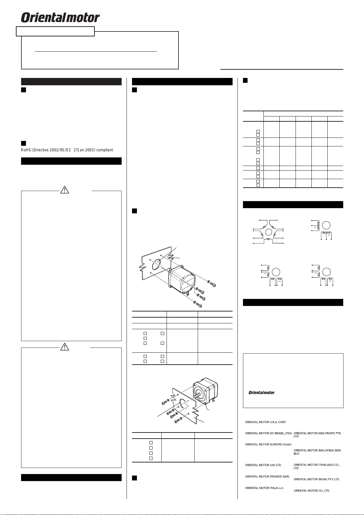
How to install the motor
Install the motor onto an appropriate flat metal plate having
excellent vibration resistance and heat conductivity. When
installing the motor, secure it with four bolts (not supplied)
through the four mounting holes (or tapped holes) provided.
Leave no gap between the motor and plate.
Mounting-pilot holder
(countersunk or
drilled through) Metal plate
4-M3P0.5
(4-No.4-40UNC)
Metal plate
Mounting-pilot holder
(countersunk or drilled through)
Handling the product without observing the instructions
that accompany a “Caution”symbol may result in injury or
property damage.
●
Do not use the motor beyond its specifications, or in-
jury or damage to equipment may result.
●
Do not touch the motor during operation or immediate-
ly after stopping. The surface is hot and may cause a
burn.
●
Do not hold the motor output shaft or motor cable. This
may cause injury.
●
Provide an emergency-stop device or emergency-stop
circuit external to the equipment so that the entire
equipment will operate safely in the event of a system
failure or malfunction. Failure to do so may result in in-
jury.
●
To prevent bodily injury, do not touch the rotating parts
(output shaft) of the motor during operation.
●
Immediately when trouble has occurred, stop running
and turn off the power. Failure to do so may result in fire,
electric shock or injury.
●
Conduct the insulation resistance measurement or with-
stand voltage test separately on the motor and the dri-
ver. Failure to do so may result in equipment damage.
●
To dispose of the motor, disassemble it into parts and
components as much as possible and dispose of indi-
vidual parts/components as industrial waste.
To verify that the unit you’ve purchased is the correct one,
check the model number shown on the identification plate.
Report any incorrect or damaged item to the branch or sales
office from which you purchased the product.
Checking the product
Before using the motor
Only qualified personnel should work with the product.
Use the product correctly after thoroughly reading the section
“Safety precautions”.
The product described in this manual has been designed
and manufactured for use in general industrial machinery,
and must not be used for any other purpose. For the power
supply use a DC power supply with reinforced insulation on
its primary and secondary sides. Oriental Motor Co., Ltd. is
not responsible for any damage caused through failure to
observe this warning.
●
Tapped hole type
The square box in the motor type will contain a number representing
the motor length. (No.4-40UNC): USA model type
Permissible overhung load
and permissible thrust load
The overhung load on the motor’s output shaft or gear out-
put shaft must be kept within the permissible values listed
below. The thrust load must not exceed the motor’s mass.
It is recommended that periodic inspections be conducted
for the items listed below after each operation of the motor.
If an abnormal condition is noted, discontinue any use and
contact your nearest office.
●
Check for any unusual noises in the motor’s bearings (ball
bearings) or other moving parts.
●
Are there any scratches, signs of stress or loose driver
connections in the motor cable?
●
Are the motor’s output shaft and load shaft out of align-
ment?
Inspection
●
Unauthorized reproduction or copying of all or part of
this Operating Manual is prohibited.
●
Characteristics, specifications and dimensions are sub-
ject to change without notice.
●
While we make every effort to offer accurate informa-
tion in the manual, we welcome your input. Should you
find unclear descriptions, errors or omissions, please
contact the nearest office.
●
is a trademark of Oriental Motor Co.,
Ltd.
© Copyright ORIENTAL MOTOR CO., LTD. 2011
0.5N·m(4.4lb-in)
1.0N·m(8.8lb-in)
2.0N·m(17.7lb-in)
3.0N·m(26lb-in)
Motor type Bolt size Tightening torque
PH533
PH544
PK56 , PH56
PK25
PK26 , PH26
PH554
PK59 , PH59
PK29 , PH29
M2.5 or M2.6
M3(No.4-40UNC)
M4
M5
1.0N·m(8.8lb-in)
Motor type Bolt size Tightening torque
PK54
PK24
PX53
PX24
M3(No.4-40UNC)
Green Blue
Red
White
Yellow
Brown
Orange
Gray
Black
Purple
AE
B
C
D
Red
Black
Yellow
Green
White Blue
A
A
BB
Wiring diagram
●
5-phase
●
2-phase 6-lead wire type
Red Yellow
/White
Red
/White
Black
Black/White
Orange/White
Orange
Yellow
A
A
BB Red Brown
White
Black
Yellow
Orange
Green
Blue
A
A
BB
●
2-phase 8-lead wire type
PH
series
●
2-phase 8-lead wire type
PK
series
The square box in the motor type will contain a number representing
the motor length.
[Unit:N(lb.)]
OPERATING MANUAL
Hazardous substances (PK series only)
RoHS (Directive 2002/95/EC 27Jan.2003) compliant
Location for installation
The motor is designed and manufactured for installation in
equipment. Install it in a well-ventilated location that pro-
vides easy access for inspection. The location must also
satisfy the following conditions:
●
Inside an enclosure that is installed indoors (provide vent
holes)
●
Operating ambient temperature
-
10°C to +50°C (+14°F to +122°F) (non-freezing)
●
Operating ambient humidity 85%, maximum (no conden-
sation)
●
Area that is free from an explosive nature or toxic gas
(such as sulfuric gas) or liquid
●
Area not exposed to direct sun
●
Area free of excessive amount dust, iron particles or the
like
●
Area not subject to splashing water (storms, water droplets),
oil (oil droplets) or other liquids
●
Area free of excessive salt
●
Area not subject to continuous vibration or excessive
shocks
●
Area free of excessive electromagnetic noise (from
welders, power machinery, etc.)
●
Area free of radioactive materials, magnetic fields or vacuum
Installation
Installing a load
When connecting a load to the motor, align the centers of
the motor’s output shaft and load shaft. Be careful not to
damage the output shaft or the bearings when installing a
coupling or pulley to the motor’s output shaft.
Warning
Caution
Stepping Motor
PK
series
,
PH
series
,
PX
series
Technical Support Tel:(800)468-3982 www.orientalmotor.com
8:30 A.M. to 5:00 P.M., P.S.T. (M-F) 7:30 A.M. to 5:00 P.M., C.S.T. (M-F)
Tel:+55-11-3266-6018
www.orientalmotor.com.br
Schiessstraße 44, 40549 Düsseldorf,
Germany
Technical Support
Tel:00 800/22 55 66 22
www.orientalmotor.de
Tel:01256-347090
www.oriental-motor.co.uk
Tel:01 47 86 97 50
www.orientalmotor.fr
Tel:02-93906346
www.orientalmotor.it 4-8-1Higashiueno,Taito-ku,Tokyo
110-8536 Japan
Tel:03-6744-0361
www.orientalmotor.co.jp
Tel:1800-806161
www.orientalmotor.com.my
Tel:1800-888-881
www.orientalmotor.co.th
Tel:+91-80-41125586
www.orientalmotor.co.in
Singapore
Tel:1800-8420280
www.orientalmotor.com.sg
• Please contact your nearest Oriental Motor office for further information.
Published in April 2018
The products do not contain the substances exceeding the
restriction values of RoHS Directive (2011/65/EU).


