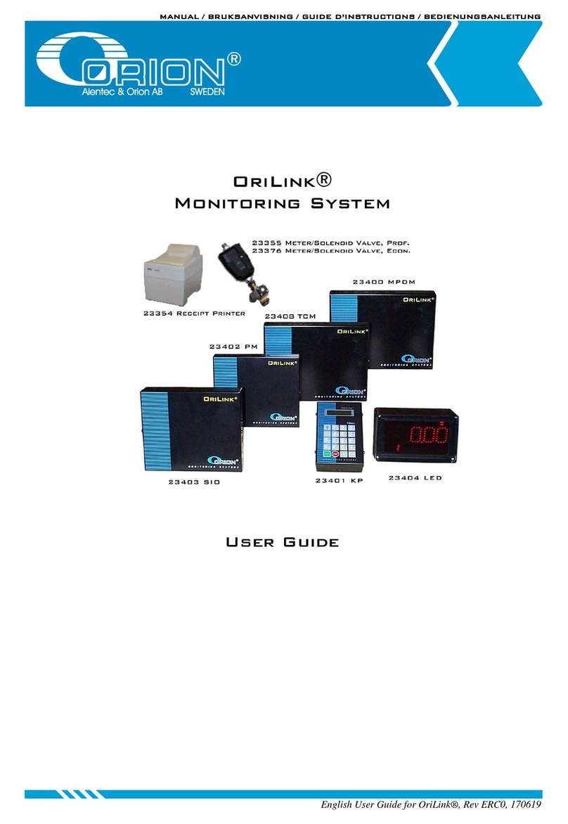
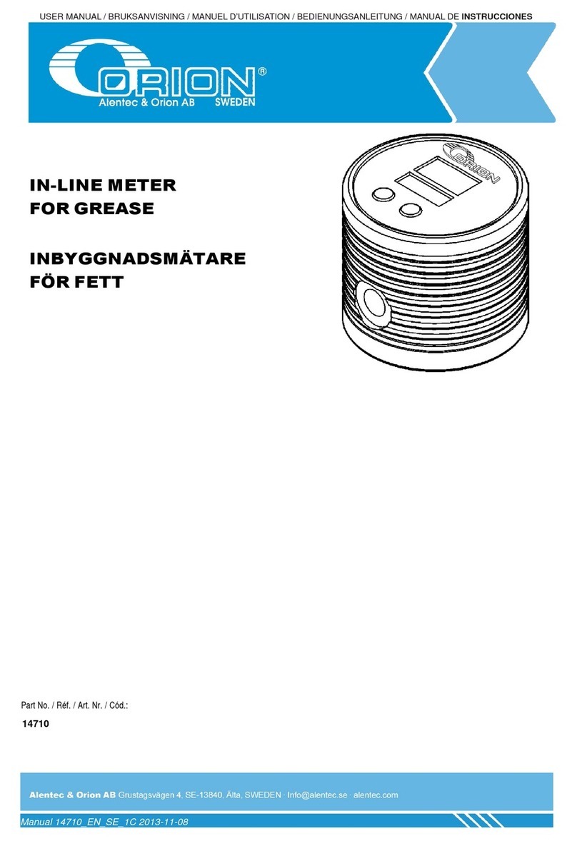
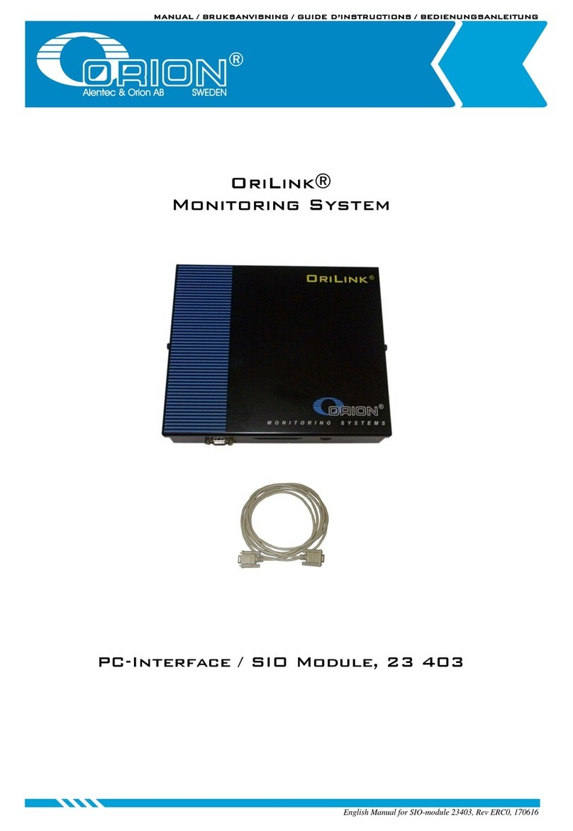
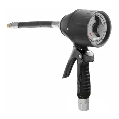
Orion 2030 User manual

Orion Model 2030
Silica Analyzer
Reference Manual
© Copyright 1998 • All Rights Reserved • Printed in U.S.A. • Version: 1.0 •Part No.: 228620-001
Orion Research Inc.
Rev. No. 001

Contact your closest Orion Representative for more information:
Orion Research Incorporated
500 Cummings Ctr
Beverly, MA 01915
Telephone: 800-225-1480
Fax: 978-927-3932
Rev. No. 001

Table of Contents
Foreword About this Manual ......................................................................................iii
What to Read ...............................................................................................iii
Starting Out..................................................................................................iv
Manual Contents.........................................................................................iv
Design Change Notice ........................................................................vi
Reproduction Notice ...........................................................................vi
Typographic Conventions .........................................................................vii
Levels of Headings...............................................................................vii
Chapter Titles/Headings in Header..................................................vii
Control Panel Entries ..........................................................................vii
Control Panel Prompts........................................................................vii
Types of Messages ...............................................................................vii
Warnings......................................................................................vii
Cautions .......................................................................................viii
Notes.............................................................................................viii
Orion Services..............................................................................................viii
Chapter 1:
Overview 1.1 Analyzer Description............................................................................1-1
1.2 Features and Functions .......................................................................1-2
1.2.1 Sample Analysis and Analyzer Calibration............................1-2
1.2.2 Analysis Cycle..............................................................................1-3
1.2.3 Calibration Cycle.........................................................................1-3
1.2.4 Cleaning Cycle.............................................................................1-3
1.3 Colorimetric Analysis ...........................................................................1-4
1.3.1 Dual Wavelength Colorimetry .................................................1-5
A. Turbidity .................................................................................1-5
B. Second Reference Measurement ........................................1-6
C. Optical Fibers in Probe ........................................................1-6
1.4 Major Components...............................................................................1-7
1.4.1 Main Assemblies..........................................................................1-7
1.4.2 Main Subsystems.........................................................................1-8
Orion Model 2030 Silica Analyzer Ref. Manual Rev. No. 001

1.5 Options....................................................................................................1-8
Chapter 2:
Hardware
Description
2.1 General....................................................................................................2-1
2.2 Main Physical Assemblies ...................................................................2-1
2.2.1 Swing Panel .................................................................................2-1
2.2.2 Sample Manifold.........................................................................2-2
2.2.3 Electronics Enclosure..................................................................2-2
2.3 Main Functional Subsystems..............................................................2-3
2.3.1 Fluidics Subsystem......................................................................2-3
A. Air Purge Fitting....................................................................2-4
B. Air Vent Fitting......................................................................2-4
C. Drain Fitting...........................................................................2-4
D. Inlet Fitting (reagent)...........................................................2-5
E. Inlet Fitting (sample) ............................................................2-5
F. Outlet Fitting (sample) .........................................................2-5
G. Inlet Fitting (standard or calibration solution) ...............2-5
H. Inlet Valve Assembly ...........................................................2-5
I. Outlet Fitting (manifold).......................................................2-5
J. Pump Assembly (piston).......................................................2-5
K. Pump Assembly (peristaltic) ...............................................2-6
L. Quick Reference Guide........................................................2-6
M. Reagent Reservoirs...............................................................2-6
N. Reaction Cell Assembly .......................................................2-6
O. Stirrer Assembly....................................................................2-7
P. Vent Valve Assembly............................................................2-8
2.3.2 Optics Subsystem........................................................................2-8
A. Immersion Probe...................................................................2-9
B. Fiberoptic Bundle Assembly................................................2-10
C. Detector Block Assembly.....................................................2-11
D. Source Block Assembly........................................................2-13
2.3.3 Electronics.....................................................................................2-13
2.3.4 Control Panel...............................................................................2-16
Rev. No. 001 Orion Model 2030 Silica Analyzer Ref. Manual
Table of Contents

Chapter 3:
Control Panel 3.1 Describing the Control Panel .............................................................3-1
3.1.1 Keypad..........................................................................................3-3
3.2 Controlling the Analyzer.....................................................................3-4
3.2.1 Dedicated Functions/Directional Keys....................................3-4
3.2.2 Menu Level Access .....................................................................3-4
A. Diagnostics..............................................................................3-5
B. Standby....................................................................................3-5
C. End an Operation .................................................................3-5
3.2.3 External Control ..........................................................................3-5
3.3 Explaining Analyzer Functions..........................................................3-6
3.3 1 Analysis Cycle..............................................................................3-6
3.3.2 Manual and Automatic Modes.................................................3-8
3.3.3 Run/Resume Function................................................................3-9
3.3.4 Blank Absorption Measurement ..............................................3-9
3.4 Navigating Menus ................................................................................3-10
3.4.1 Editing a Value............................................................................3-11
3.4.2 Scroll Menus.................................................................................3-11
3.5 Describing Sequences...........................................................................3-12
3.5.1 Primary Mode Functions...........................................................3-12
3.5.2 End Sequence Options...............................................................3-12
Chapter 4:
Installation 4.1 Inspecting and Unpacking the Analyzer.........................................4-1
4.2 Preparing for Physical Installation....................................................4-2
4.3 Mounting the Analyzer .......................................................................4-4
4.3.1 Installing the Air Purge..............................................................4-4
4.4 Performing Electrical Installation .....................................................4-5
4.4.1 Installing AC Wiring...................................................................4-5
4.4.2 Installing DC Wiring ..................................................................4-10
A. Digital Input Lines................................................................4-10
B. Analog Output Lines............................................................4-11
C. RS-232C Wiring .....................................................................4-11
Orion Model 2030 Silica Analyzer Ref. Manual Rev. No. 001
Table of Contents

Chapter 5:
Analyzer Startup 5.1 Installing the Startup Kit.....................................................................5-1
5.1.1 Installing the Magnetic Stirrer..................................................5-2
5.1.2 Installing the Peristaltic Pump Tubing ...................................5-3
5.2 Preparing Solutions ..............................................................................5-5
5.2.1 Installing Reagent Check Valves..............................................5-6
5.3 Connecting the Fluidics.......................................................................5-7
5.4 Powering Up the Analyzer.................................................................5-8
5.5 Priming the Fluidics .............................................................................5-9
5.6 Checking and Adjusting Sample Flow Rate ...................................5-10
5.7 Changing the Time and Date ............................................................5-11
5.8 Calibrating for the First Time.............................................................5-12
5.9 Placing the Analyzer into Service......................................................5-13
Chapter 6:
Routine
Operation 6.1 Accessing Routine Functions..............................................................6-2
6.2 Stopping the Analyzer.........................................................................6-3
6.3 Choosing a Function............................................................................6-3
6.4 Performing a Function.........................................................................6-3
6.5 Running a Calibration..........................................................................6-4
6.5.1 Running a Grab Analysis...........................................................6-6
6.5.2 Validating a Calibration Standard ...........................................6-8
6.6 Running an Analysis............................................................................6-9
6.6.1 Selecting Standby Operation....................................................6-10
6.6.2 Printing Parameters....................................................................6-10
6.6.3 Setting the User Access Level...................................................6-10
6.7 Performing Startup Functions............................................................6-12
6.7.1 Priming the Fluidics ...................................................................6-12
6.7.2 Checking the Flow Rate.............................................................6-13
6.7.3 Setting the Time and Date ........................................................6-13
6.8 Restarting the Analyzer.......................................................................6-13
6.8.1 Purging the Fluidics Lines.........................................................6-13
6.9 Describing Display Results..................................................................6-14
Rev. No. 001 Orion Model 2030 Silica Analyzer Ref. Manual
Table of Contents

Chapter 7:
Advanced
Operation 7.1 Accessing Advanced Functions..........................................................7-2
7.1.1 Returning to the Operator Level .............................................7-3
7.1.2 Explaining Standby Operation.................................................7-3
7.1.3 Saving and Recovering ..............................................................7-3
7.2 Defining a Calibration Setup..............................................................7-4
7.2.1 Set Calibration Standard Concentration.................................7-6
7.2.2 Set Calibration Standard Absorbance......................................7-7
7.2.3 Set Calibration Device................................................................7-8
7.2.4 Set Calibration Method..............................................................7-8
7.2.5 Set Calibration Type...................................................................7-9
7.2.6 Set Calibration Repeat Alarm ...................................................7-9
7.2.7 Save Calibration Setup...............................................................7-11
7.2.8 Recover Calibration Setup.........................................................7-11
7.3 Defining an Analysis Method ............................................................7-12
7.3.1 Set Cell Wash...............................................................................7-13
7.3.2 Set Reagent Addition Sequence ...............................................7-15
7.3.3 Set Blank Step..............................................................................7-17
7.3.4 Set Post Wash Sequence............................................................7-18
7.3.5 Set Stability Factor ......................................................................7-19
7.3.6 Select Calibration Setup.............................................................7-20
7.3.7 Save Analysis Method................................................................7-20
7.3.8 Recover Analysis Method..........................................................7-20
7.4 Modifying Pump Information............................................................7-21
7.4.1 Changing the Pump Type.........................................................7-23
7.4.2 Setting the Priming Action........................................................7-24
7.4.3 Setting Pump Viscosity..............................................................7-24
7.4.4 Setting Pump Flow Rate............................................................7-25
7.4.5 Saving and Recovering ..............................................................7-25
7.5 Changing Stream-Related Information ............................................7-26
7.5.1 Set Analog Output......................................................................7-27
7.5.2 Set Alarm Levels..........................................................................7-29
7.5.3 Set Viscosity Factor.....................................................................7-30
7.5.4 Set External Sample Device ......................................................7-31
7.5.5 Set Flow Rate ...............................................................................7-31
7.5.6 Modify Calibration Curve .........................................................7-32
7.5.7 Set Offset Value...........................................................................7-32
7.5.8 Set Gain Value.............................................................................7-33
7.5.9 Save Stream Information...........................................................7-33
Orion Model 2030 Silica Analyzer Ref. Manual Rev. No. 001
Table of Contents

7.5.10 Recover Stream Information...................................................7-33
7.6 Setting up Sequences ...........................................................................7-34
7.6.1 Edit Stream Sequence.................................................................7-37
7.6.2 Set Sampling Frequency............................................................7-39
7.6.3 Edit Calibration Sequence .........................................................7-39
7.6.4 Set Calibration Frequency .........................................................7-39
7.6.5 Cleaning Cycle.............................................................................7-40
7.6.6 Save Sequence Information.......................................................7-41
7.6.7 Recovering Sequence Information...........................................7-41
7.7 Setting up Outputs...............................................................................7-41
7.7.1 Set Time and Date ......................................................................7-42
A. Setting the Time ...................................................................7-43
B. Setting the Date.....................................................................7-43
7.7.2 Set Relay Function......................................................................7-44
7.7.3 Set Input Functions ....................................................................7-45
7.7.4 Set Special Function ...................................................................7-47
7.7.5 Set Communications...................................................................7-47
A. Setting the Printer Port........................................................7-50
B. Setting the External Communications Port .....................7-50
7.7.6 Save Output Information ..........................................................7-50
7.7.7 Recover Output Information....................................................7-50
7.8 Setting Up Parameters.........................................................................7-51
7.8.1 Set Standby Wash .......................................................................7-53
A. Setting the Standby Wash Volume...................................7-53
B. Setting the Standby Timeout Period.................................7-53
7.8.2 Set Stirrer Mode ..........................................................................7-54
7.8.3 Set Stirring Action.......................................................................7-54
7.8.4 Set Display Format .....................................................................7-55
7.8.5 Set Motor Action .........................................................................7-55
7.8.6 Set Pass Code...............................................................................7-56
7.8.7 Save Parameters ..........................................................................7-56
7.8.8 Recover Parameters ....................................................................7-56
7.9 Save Unit Configuration......................................................................7-56
7.10 Recover Unit Configuration..............................................................7-56
7.11 Printing System Parameters..............................................................7-57
7.11.1 Print Fluidics..............................................................................7-58
7.11.2 Print Calibration Setups...........................................................7-59
7.11.3 Print Methods ...........................................................................7-59
7.11.4 Print Stream Information ........................................................7-59
7.11.5 Print Sequences .........................................................................7-59
Rev. No. 001 Orion Model 2030 Silica Analyzer Ref. Manual
Table of Contents

7.11.6 Print Outputs.............................................................................7-60
7.11.7 Print Parameters........................................................................7-60
7.11.8 Print All Parameters..................................................................7-60
7.11.9 Print System Status...................................................................7-60
7.12 Reviewing Stored Results..................................................................7-61
7.12.1 Review Calibration ...................................................................7-62
7.12.2 Print Calibrations ......................................................................7-62
7.12.3 Review Analyses........................................................................7-63
7.12.4 Print Analyses............................................................................7-63
7.13 Reviewing Alarms...............................................................................7-64
7.13.1 View Active Alarms ..................................................................7-65
7.13.2 Print All Alarms.........................................................................7-65
7.13.3 Reset All Alarms ........................................................................7-65
7.14 Testing the Hardware........................................................................7-66
7.14.1 Reset All......................................................................................7-67
7.14.2 Fluidics Control.........................................................................7-67
7.14.3 Check Flow Rates......................................................................7-69
7.14.4 Lamp Control.............................................................................7-70
7.14.5 Temperature Control................................................................7-71
7.14.6 Test Relays..................................................................................7-71
7.14.7 Test Analog Outputs ................................................................7-72
7.15 Viewing Hardware Settings..............................................................7-74
7.15.1 Show Detector Output.............................................................7-75
7.15.2 Show Absorbance, Transmittance..........................................7-77
7.15.3 Show Main ADC .......................................................................7-78
7.15.4 Show Power Rails .....................................................................7-79
7.15.5 Show Revision Level ................................................................7-79
7.16 Adjusting Hardware Settings ...........................................................7-80
7.16.1 Automatic Hardware Calibration...........................................7-81
7.16.2 Manual Hardware Calibration................................................7-81
7.16.3 Save Hardware Setup...............................................................7-84
7.16.4 Recover Hardware Setup ........................................................7-84
7.17 Clearing Sections of Memory...........................................................7-85
7.17.1 Clear Calibrations......................................................................7-86
7.17.2 Clear Test Results......................................................................7-86
7.17.3 Reset Calibration Setup............................................................7-86
7.17.4 Reset Test Method ....................................................................7-86
7.17.5 Reset Clock.................................................................................7-86
7.17.6 Reset Backup..............................................................................7-86
7.17.7 Reset Memory............................................................................7-86
Orion Model 2030 Silica Analyzer Ref. Manual Rev. No. 001
Table of Contents
Chapter 8:
Maintenance 8.1 Scheduled Maintenance.......................................................................8-3
8.1.1 Reseating Piston Pump Seals....................................................8-4
A. Flushing Lines with Water..................................................8-4
B. Seating the Pump Seals........................................................8-5
C. Reconnecting and Refilling Reagent Lines......................8-6
8.1.2 Replacing Piston Pump Seals....................................................8-7
A. Flushing Lines with Water..................................................8-7
B. Removing the Pump Assemblies .......................................8-8
C. Disassembling the Pump.....................................................8-9
D. Installing New Seals.............................................................8-10
E. Reassembling the Pump.......................................................8-11
F. Reinstalling Pump Assemblies ............................................8-11
G. Seating the Pump Seals.......................................................8-11
H. Reconnecting and Filling Reagent Lines.........................8-11
8.1.3 Performing Reagent Pump Flow Rate Calibration...............8-12
8.1.4. Measuring Flow Rate ................................................................8-12
8.1.5 Inspecting and Cleaning the Immersion Probe ....................8-12
8.1.6 Replacing the Reaction Cell O-ring.........................................8-13
8.2 Miscellaneous Maintenance................................................................8-14
8.2.1 Replacing Standard Tubing ......................................................8-14
A. Flushing the Lines with Water ..........................................8-14
B. Replacing the Tubing ...........................................................8-14
C. Replacing the Immersion Probe Body..............................8-15
8.2.2 Replacing the Lamp....................................................................8-16
8.2.3 Replacing the Optical Filter ......................................................8-17
8.2.4 Resetting the Memory................................................................8-19
8.3 Shutdown and Restart Procedures ...................................................8-20
8.3.1 Performing Short-term Shutdown...........................................8-20
8.3.2 Restarting After Short-term Shutdown...................................8-20
8.3.3 Performing Extended Shutdown.............................................8-20
A. Flushing the Standard Lines...............................................8-20
B. Cleaning Sample/Reaction Cell and Probe ......................8-21
Rev. No. 001 Orion Model 2030 Silica Analyzer Ref. Manual
Table of Contents

Chapter 9:
Troubleshooting 9.1 Troubleshooting.....................................................................................9-1
9.2 Corrupt Memory...................................................................................9-2
9.2.1 Initiating a Wildcard Reset........................................................9-2
9.2.2 What to do if Memory is Corrupt............................................9-2
9.2.3 What to do if Backup is Corrupt..............................................9-3
9.3 Troubleshooting Chart.........................................................................9-4
Appendix A: Parts
Lists
Appendix B:
Customer Service
Information
B.1 Telephone Numbers ............................................................................B-1
B.2 Fax Numbers .........................................................................................B-1
B.3 Warranty ................................................................................................B-1
Appendix C: List
of Relay
Functions C.1 Concentration Alarms .........................................................................C-2
C.2 Calibration Repeat Alarm...................................................................C-3
C.3 General Faults.......................................................................................C-4
C.4 Level and Flow Alarms.......................................................................C-5
C.5 Hardware Alarms.................................................................................C-6
C.6 Other Alarms ........................................................................................C-8
Appendix D:
Reports
Appendix E:
General
Specifications
Appendix F:
Warning, Alarm,
and Fault
Messages
Orion Model 2030 Silica Analyzer Ref. Manual Rev. No. 001
Table of Contents

List of Illustrations
Figure 1-1 Orion Model 2030 Analyzer, Front View
(Front Door Not Shown)....................................................1-2
Figure 1-2 Effects of Turbidity ..............................................................1-5
Figure 1-3 Major Components..............................................................1-7
Figure 2-1 Fluidic Path (Functional) ....................................................2-3
Figure 2-2 Fluid Handling Components.............................................2-4
Figure 2-3 Reaction Cell Assembly.......................................................2-6
Figure 2-4 Detailed Reaction Cell and Manifold ..............................2-7
Figure 2-5 Optics Subsystem.................................................................2-8
Figure 2-6 Immersion Probe Assembly ...............................................2-9
Figure 2-7 Fiberoptic Bundle Assembly ..............................................2-10
Figure 2-8 Detector Block Assembly....................................................2-11
Figure 2-9 Source Block Assembly .......................................................2-13
Figure 2-10 Electronics Enclosure...........................................................2-14
Figure 3-1 Control Panel........................................................................3-1
Figure 3-2 Orion Model 2030 Analyzer Menu Structure ................3-10
Figure 4-1 Installation Dimensions ......................................................4-3
Figure 4-2 Power Supply Assembly.....................................................4-6
Figure 4-3 Terminal Blocks on Main Board .......................................4-7
Figure 4-4 Terminal Blocks on Relay Board ......................................4-8
Figure 4-5 Optional Multiplexer Board Connections.......................4-8
Figure 4-6 ACTIVATE Strobe Signal Timing Diagram.....................4-10
Figure 4-7 Connecting the RS-232C Cable .........................................4-12
Orion Model 2030 Silica Analyzer Ref. Manual Rev. No. 001

Figure 5-1 Stir Bar Installation and Reaction Cell ............................5-2
Figure 5-2 Installing Peristaltic Pump Tubing...................................5-3
Figure 5-3 Tubing Paths.........................................................................5-4
Figure 5-4 Fluid Level Requirement ...................................................5-5
Figure 5-5 Reagent Check Valve Installation.....................................5-6
Figure 8-1 Orion Model 2030 Analyzer Front View
(Front Door Not Shown)....................................................8-2
Figure 8-2 Reagent and Standard Tubing Paths...............................8-6
Figure 8-3 Piston Pump, Exploded View ...........................................8-9
Figure 8-4 Preforming Seals ..................................................................8-10
Figure 8-5 Reaction Cell Assembly.......................................................8-14
Figure 8-6 Probe Detail .........................................................................8-15
Figure 8-7 Source Block Detail..............................................................8-16
Figure 8-8 Detector Block Detail...........................................................8-18
Figure D-1 Fluidics Device Printout .....................................................D-1
Figure D-2 Calibration Setup Printout .................................................D-2
Figure D-3 Method Printout .................................................................D-2
Figure D-4 Stream Information Printout .............................................D-3
Figure D-5 Sequence Information Printout.........................................D-4
Figure D-6 Digital Input/Output Information Printout....................D-5
Figure D-7 Parameters Information Printout......................................D-6
Figure D-8 System Status Information Printout.................................D-6
Figure D-9 Stored Calibrations Information Printout .......................D-7
Figure D-10 Alarm Information Printout...............................................D-7
Rev. No. 001 Orion Model 2030 Silica Analyzer Ref. Manual
List of Illustrations

Foreword
About this
Manual
This Reference Manual provides the information necessary to obtain the
maximum benefits from the Orion Model 2030 Silica Analyzer. All operat-
ing instructions, functional descriptions, illustrations, and other relevant
information are contained in this manual. Descriptions of the system
hardware and user-interface software (the control panel) are included, as
is an overview of the analytical techniques employed in the analyzer.
Step-by-stepinstructions guide you through alloperating proceduresand
field programming.
The Orion Model 2030 Series Analyzer has been designed to be very easy
touse. Each analyzer in thisfamily runsin a fully automated modefor rou-
tine, day-to-day monitoring. The need for operator interaction is minimal.
Accordingly, the information required by the routine operator of this ana-
lyzer is modest, and that information is provided in Chapter 6, Routine
Operation, of this manual. Do not operate your Orion Model 2030 Silica
Analyzer until you have read Chapter 6.
What to Read Table 1.1 provides assistance in determining which chapter(s) of this man-
ual to read or scan, depending upon your intent.
Table 1.1 Guide to the Reference Manual
If you wish to... Refer to
Chapter(s)
Learn how to use this Reference Manual Foreword
Learn to use the analyzer in routine operation 6
Change the analyzer’s operating characteristics 7
or run tests
Place the analyzer in service for the first time 4, 5, 6
Determine maintenance requirements 8
Troubleshooting operating problems 9
Learn about the analyzer’s methods and 2
components
Access reference information A-F
Orion Model 2030 Silica Analyzer Ref. Manual Rev. No. 001
iii

After reading or scanning the appropriate chapters of this manual, you
will find the supplied Quick Reference Guide to provide a useful sum-
mary of system capabilities and operating procedures. The Quick Refer-
enceGuide wasshipped with your analyzer, andshould bekept handy.
Starting Out If you are placing your Orion Model 2030 Silica Analyzer in service for
the first time, you must read through Chapter 4 (Installation) and Chap-
ter 5 (Analyzer Startup). Follow the step-by-step instructions provided.
You may discover a need for additional expert help at your site as you step
through these procedures. You can also contact your regional Orion Re-
search, Inc. representative or Orion’s Customer Service for assistance in
properlyinstalling andstarting up your Orion Model2030 SilicaAnalyzer.
After installing and starting up your analyzer, you should read Chapter 6
and insure that all operators at your site read it, too. You may then find it
helpful to read or scan Chapters 7, 3, and 8.
NOTE: You cannot damage the Orion Model 2030 Silica Analyzer by
pressing the “wrong” key on its control panel. While you may not
achievethe resultyou expectedand the outcome may cause a minorin-
convenience, the analyzer always recovers intact. Pressing the [STOP]
key ends the current procedure, leaving all values unchanged.
Manual Contents Information in this manual is organized as follows:
Chapter 1, Overview, provides an overview of the Orion Model 2030 Sil-
ica Analyzer, including a description of the analyzer’s features and func-
tions (measurement process and modes of operation), a review of color-
imetric analysis in general and the dual-wavelength colorimetric tech-
nique employed by the Orion Model 2030 Silica Analyzer in particular,
and identification of the analyzer’s three major assemblies and four sub-
systems and available options.
Chapter 2, Hardware Description, identifies and describes the three main
physical assemblies of the Orion Model 2030 Silica Analyzer (swing panel,
samplemanifold, andelectronics enclosure)and the four major functional
analyzer subsystems (fluidics, optics, electronics, and control panel).
Chapter 3, Control Panel Description, explains how to use the control
panel. Specific topics include: controlling the analyzer; explaining ana-
lyzer functions; navigating the control panel menus; and understanding
sequences.
Chapter 4, Installation, supplies these procedures to help you in unpack-
ing and installing your Orion Model 2030 Silica Analyzer: inspecting and
Rev. No. 001 Orion Model 2030 Silica Analyzer Ref. Manual
iv
Starting Out Foreword

unpacking the analyzer; preparing for physical installation; mounting the
analyzer; and performing electrical installation.
Chapter 5, Analyzer Setup, furnishes procedures you need to help start
up the Orion Model 2030 Silica Analyzer for the first time and bring it into
on-line service. These procedures include: installing the startup kit; pre-
paringsolutions; connecting thefluidics; powering upthe analyzer; prim-
ing the fluidics; checking and adjusting the sample flow rate; checking
and adjusting the time and date; calibrating for the first time; and placing
the analyzer into service.
Chapter 6, Routine Operation, describes the routine operation of the ana-
lyzer. Topics discussed in this chapter include: accessing routine func-
tions; stopping the analyzer; choosing a function; performing a function
(running a calibration, validating a calibration standard, running an
analysis,selecting standbyoperation, printing parameters, and settingthe
useraccess level); performingstartup functions (purgingthe fluidics lines,
checking the flow rate, setting the time and date); and restarting the ana-
lyzer.
Chapter 7, Advanced Operation, details the advanced functions available
to an authorized user of the Orion Model 2030 Silica Analyzer, functions
that go beyond those typically encountered in routine operation (see
Chapter 6). Advanced functions fall into three categories: setup functions;
calibration/analysis functions; and diagnostics functions.
Chapter 8, Maintenance, provides the maintenance procedures applica-
ble to the Orion Model 2030 Silica Analyzer. Maintenance procedures cov-
ered here fall into three categories: scheduled maintenance procedures;
miscellaneous maintenance procedures; and shutdown and restart proce-
dures.
Chapter 9, Troubleshooting, contains troubleshooting information, in-
cluding an easy-to-use troubleshooting chart to diagnose and correct
many common system problems.
Appendix A, Parts Lists, supplies part numbers for the Orion Model 2030
Silica Analyzer.
Appendix B, Customer Service Information, provides Customer Service
and Technical Service telephone and fax numbers.
Appendix C, List of Relay Functions,furnishes alist ofrelay functions.
Orion Model 2030 Silica Analyzer Ref. Manual Rev. No. 001
v
Foreword Manual Contents

Appendix D, Reports, supplies examples of the various reports produced
by the Orion Model 2030 Silica Analyzer.
Appendix E, General Specifications, lists the general specifications of the
Orion Model 2030 Silica Analyzer.
Appendix F, Warning, Alarm, and Fault Messages, lists the types of
warning, alarm, and fault messages and the appropriate corrective actions
for each.
The INDEX is an alphabetical, hierarchical (multi-level) listing of all head-
ings, sub-headings, and important topics contained in this manual.
Design Change
Notice
Due to design changes and product improvements, information in this
manual is subject to change without notice. The manufacturer reserves
the right to change hardware and/or software design at any time, which
may subsequently affect the contents of this manual.
The manufacturer assumes no responsibility for any errors that may ap-
pear in this manual. The manufacturer will make every reasonable effort
to ensure that this Reference Manual is up to date and corresponds with
your shipped Orion Model 2030 Silica Analyzer.
Reproduction Notice Neitherthis manualnor anypart of it may be reproduced, photocopied,or
electronically transmitted in any way without the advanced written per-
mission of Orion Research, Inc.
Rev. No. 001 Orion Model 2030 Silica Analyzer Ref. Manual
vi
Manual Contents Foreword

Typographic
Conventions
Levels of Headings Headings and sub-headings are arranged both by decimal numbering
and typographic sizing. This is so you can delineate topic subordination
and can find cross references conveniently. These heading levels are used,
in descending order: Chapter Head (Chapter Number: Title), Head 1 (1.1,
2.1, etc.), Head 2 (1.1.1, 2.1.1, etc.), and Head 3 (A, B, C, etc.).
Chapter
Titles/Headings in
Header
To make it easier for you to identify your place in the manual, a running
header at the top of each page notes the appropriate chapter number and
chapter title. In addition, to identify the specific major topic on each page,
the first level heading is also included in the page header.
Control Panel Entries Whenever you are instructed to make an entry on the control panel, the
keys you must press are printed in boldface type enclosed in brackets. For
example, the “RUN” (bottom leftmost) key on the control panel (see Fig-
ure 3-1) is referenced as:
[RUN]
In certain situations, the top row of keys on the control panel performs
special functions as indicated on the bottom line of the display. Such soft
keys are represented as upper case characters enclosed in brackets. For ex-
ample, the top leftmost key in Figure 3-1 ([F1] or [LEFT]) performs the
SETUP function, and is referenced as:
[SETUP]
Control Panel
Prompts
System prompts (requests for information or explanatory displays) ap-
pearing on the control panel are printed in a Courier typeface, on separate
lines,indented—to distinguishthem from other text. Anexample follows:
This is a sample system prompt
Types of Messages Three types of messages may appear in this manual: Warnings, Cautions,
and Notes.
Warnings
Warnings indicate situations that could result in the injury of a human op-
erator or bystander. Warnings are printed in all uppercase characters in
boldface type, between two heavy horizontal rules, as in the following ex-
ample:
Orion Model 2030 Silica Analyzer Ref. Manual Rev. No. 001
vii
Foreword Typographic Conventions

WARNING: NEVER INSTALL OR OPERATE THE Orion Model
2030 Silica Analyzer WHILE STANDING IN WATER. YOU MAY BE
ELECTROCUTED!
Cautions
Cautions indicate situations that could damage the Orion Model 2030 Sil-
ica Analyzer. Cautions are printed in mixed case characters in boldface
type, between two heavy horizontal rules, as in this example:
Caution: Failure to connect the Orion Model 2030 Silica Analyzer to
the proper electrical voltage as specified herein could result in damage
to the analyzer.
Notes
Notes indicate miscellaneous information. Notes are printed in mixed
casecharacters, innormal type, within a centeredbox, asin thisexample:
NOTE: For details on Orion customer service policies, refer to Appen-
dix B.
Orion Services Orion Research Incorporated’s products provide customers with the fin-
est solutions to their on-line wet chemistry problems. Orion’s Customer
Service is available weekdays from 9:00 am to 5:00 pm Eastern time. The
Customer Service telephone number is (800) 225-1480. Technical assis-
tance is also available from regional offices.
This is Revision Number 002 of the Orion Model 2030 Series Reference Man-
ual, Orion Document Number 228620-001, with an effective date of June
1998.
Rev. No. 001 Orion Model 2030 Silica Analyzer Ref. Manual
viii
Orion Services Foreword
Table of contents
Other Orion Measuring Instrument manuals

Orion
Orion OriLink 23441 User manual

Orion
Orion 20400 User manual

Orion
Orion OriLink 23408 User manual

Orion
Orion 24759 User manual

Orion
Orion OriLink User manual

Orion
Orion 8FIDKR User manual

Orion
Orion 710A plus User manual

Orion
Orion 24736 User manual

Orion
Orion OriLink User manual

Orion
Orion OriLink User manual