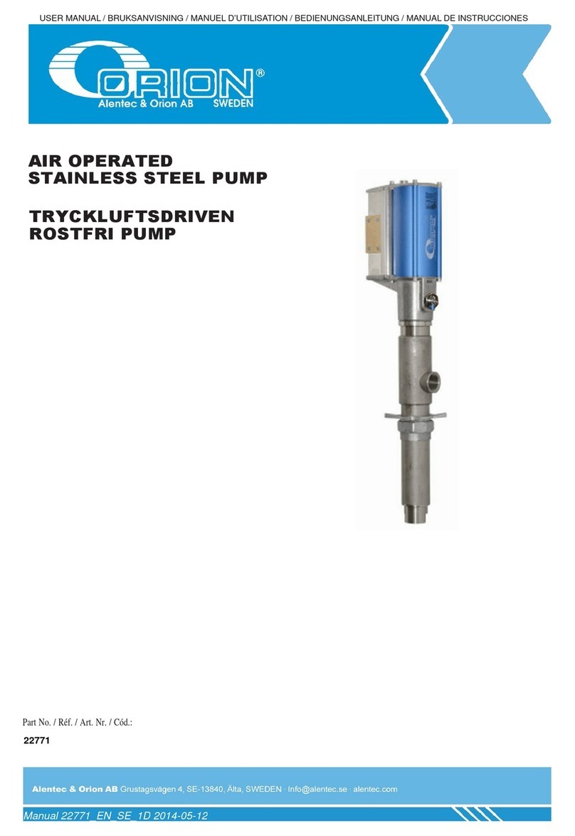
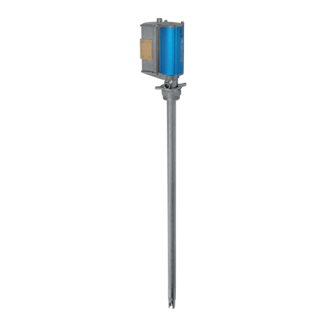
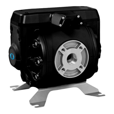
Orion 22802 User manual

USER MANUAL / BRUKSANVISNING / MANUEL D’UTILISATION / BEDIENUNGSANLEITUNG / MANUAL DE INSTRUCCIONES
Manual 22802_EN_SE1C 2013-11-19
Part No. / Réf. / Art. Nr. / Cód.:
22802
AIR OPERATED SUCTION PUMP 1:1
TRYCKLUFTSDRIVEN
SUGPUMP 1:1

Manual 22802_EN_SE_1C
2(8)
Technical data
228
02
Pressure ratio 1:1
Total length 470 mm
Pump tube length 180 mm
Pump tube diameter Ø52 mm
Gross Weight resp. Net
weight
3.2 kg / 7.05 lbs
2.8 kg / 6.2 lbs
Box dimension 520x100x100 mm
Max air pressure 1.0 Mpa/ 145 psi
Min air pressure 0.2 Mpa/ 29 psi
Max fluid pressure 1.0 Mpa/ 145 psi
Burst pressure Min. 7.0 Mpa/ 1000 psi
Free delivery (Motor Oil SAE
10-30 at 20°C and max air
pressure)
approx. 25 l/min
Air inlet thread BSP ¼” female/ G ¼”
Fluid outlet thread BSP ¾” female/ G ¾"
Fluid inlet BSP 1” female/ G 1”
Noice level at 0,7 MPa 78 dB
Drum adapter, G 2" (BSP) Included
T
ekniska data
228
02
Tryckförhållande 1:1
Totallängd 470 mm
Pumprörslängd 180 mm
Pumprörs diameter Ø52 mm
Bruttovikt i kartong resp. nettovikt
3.2 kg resp. 2.8 kg
Kartongdimension 520x100x100 mm
Max. lufttryck 1.0 Mpa/ 10 Bar
Min. lufttryck 0.2 Mpa/ 2 Bar
Max. vätsketryck 1.0 Mpa/ 10 Bar
Sprängtryck Min. 7.0 Mpa/ 70 Bar
Fritt avgivet flöde (Motorolja SAE
10-30 vid 20°C och max.lufttryck)
Ca 25 l/min
Luftanslutning G ¼” (inv)
Vätskeutlopp G ¾"(inv)
Vätskeinlopp G 1” (inv)
Buller vid 0.7 Mpa 78 dB
Fatadapter G 2” Ingår
General
The air operated pump has two main parts. One double acting air
motor driving a double acting liquid pump. The liquid is sucked into
the pump tube through the bottom valve when the piston is on the
upward stroke and is discharged in both up and down strokes.
The relationship between the area of the air piston and the area of the
pump piston decides the pressure ratio. The pressure ratio is 1:1 and
the theoretic pressure when the pump has stopped is the same for
both oil and air.
The air is exhausted through a sintered brass silencer. This pump is
equipped with a speed regulated mechanism which prevents the
pump from racing when the pump has finished its mission.
Safety precautions
The pump is to be used with non-corrosive fluids like oil, light grease
and may not be used for other purposes. It must not be used for
pumping petrol or other explosive liquids.
WARNING! The pump contains zinc and aluminium materials, which
can react with some solvents and create explosive gases.
Check that all accessories/components are suitable for the working
pressure of the system.
Do not exceed the maximum air pressure of the pump 1.0 MPa (10
Bar).
The system must be tested to 1.3 times the working pressure before
being put into operation.
All test results must be kept and filed together with this manual.
Close and disconnect the air supply and relieve the liquid pressure in
the system before any work to the pump or the system is carried out.
Only use genuine manufacturers spare parts. Never use any worn or
damaged spare parts.
Allmänt
Den tryckluftsdrivna vätskepumpen har två huvuddelar: En
dubbelverkande kolvmotor och en dubbelverkande vätskedel. Vätskan
sugs in i pumpröret genom bottenventilen vid uppåtgående rörelse på
kolven. Vätska trycks ut både vid uppåtgående och nedåtgående rörelse.
Förhållandet mellan luftkolvens area och pumpkolvens area anger
tryckförstärkningen. Om tryckförstärkningen är 1:1 blir det teoretiska
trycket, när pumpen stannat, lika med lufttrycket.
Returluften blåses ut och dämpas via en ljuddämpare som är tillverkad
av sintrad mässing. Den här pumpen är försedd med en fartreglerad
mekanism som gör att pumpen inte kan ”rusa” när vätskan tar slut.
Produktsäkerhetsanvisningar
Pumpen är avsedd för pumpning av icke korrosiva och
petroleumbaserade vätskor som oljor och löst fett. Pumpen får EJ
användas för andra ändamål eller för pumpning av bensin eller andra
explosiva vätskor.
VIKTIGT! Pumpen innehåller zink och aluminium som kan reagera med
vissa lösningsmedel och bilda explosiva gaser.
Kontrollera att alla anslutna komponenter är avsedda och lämpade för
systemets arbetstryck.
Använd inte högre lufttryck än nödvändigt för att uppnå lämplig
systemfunktion.
Provtryck alla rörledningar med 1.3 x systemets arbetstryck innan det tas
i drift.
Provtryckningen ska dokumenteras och sparas tillsammans med denna
bruksanvisning.
Stäng av eller koppla bort trycklufttillförseln och avlasta vätskeledningen
innan något arbete på pump eller system påbörjas.
Använd eller återmontera aldrig en sliten eller skadad detalj.
Do not direct outlet valves or any other dispensing valve against the
body or any other person as the liquid can penetrate the skin or damage
the eyes.
In the event of accidental penetration of the liquid into the skin or eyes
seek immediate medical advice

Manual 22802_EN_SE_1C
3(8)
Periodically inspect all system components for leakage or damage,
especially the hoses which can be worn out due to wear and age.
Rectify any defects immediately.
If there is a risk of the line pressure increasing due to direct heat on
the pipe work from example hot air blowers, heaters, radiators etc.
causing the fluid to expand in the pipe work, a pressure relief valve
must be fitted to prevent equipment failure, or burst hoses. The
pressure relief valve should be fitted into the pump housing or
between the pump outlet and the discharge hose.
Always turn off the air pressure to the pump when the premises are
unattended. An accident or hose break can occur
Installation
Remove the protective packing from the pump including plugs in the
air inlet and the fluid outlet.
Remove the drum adaptor from the pump tube. Mount the adapter
into the 2" hole in the floor stand or pump bracket.
Connect the liquid outlet hose into the outlet of the pump (G ¾" f).
Mount the air nipple into the air inlet (G ¼" f).
Warning! If the air pressure in the system is higher than the working
pressure of the pump it will be necessary to install an air regulator
and gauge into the air line prior to the pump.
A shut-off valve should always be installed into the air line before
fixing the air hose, filter, regulator and gauge.
The pump is pre-lubricated with silicon grease. It is not necessary to
use a lubricator under normal operating conditions.
Warning!
If a lubricator has been used with the pump it is
necessary to continue using it. This is because the oil from the
lubricator will have washed the silicon grease away. If the lubricator is
not continuously used this could result in the pump being damaged.
The pipe work must be installed according to local regulations for this
type of equipment.
Do not mount a pump directly onto a sheet metal wall or similar
construction, which can create noise resonance and augment the
normal noise level of the pump.
A hose must be mounted between the outlet of the pump and the
fixed pipe work.
A shut-off valve must always be installed at the beginning of the pipe
work to make service easier and to make it possible to cut off the flow
of liquid when necessary.
Always mount a suction filter BEFORE the intake thread at the pump,
to take care of dirt and foreign particles and avoid any damage to the
pump packing and sealing surface. Don’t forget to regularly clean and
inspect the filter to ensure optimum performance. We recommend
using strainer 29300 with a 36 mesh filter cartridge.
Start up
When starting up the system for the first time, all valves should be
opened to bleed air from the system. It may be necessary to bleed the
system at a high point to release any air pockets. These air pockets
can be difficult to remove but to avoid any foam it is essential to get
ride of them.
Rikta aldrig ventilens eller andra distributionsenheters utloppsmunstycke
mot någon kroppsdel eller någon annan person. En tunn stråle av
vätskan tränger lätt igenom huden och kan skada ögonen.
Skulle trots denna varning ändå, olja eller liknade medel tryckas in i
huden, kontakta omedelbart läkare för vidare undersökning.
Kontrollera regelbundet alla komponenter med avseende på läckage och
eventuella skador. Speciellt slangledningar är utsatta för nötning och
åldring.
Om det finns risk för tryckhöjning av vätskan genom uppvärmning av
rören eller genom att slangar blir överkörda måste en säkerhetsventil
monteras. Den ska monteras i därför avsett hål på utloppshuset eller
mellan pump och rörledning så nära pumpens utlopp som möjligt.
Stäng alltid av eller koppla bort tryckluften till pumpen över natten och
vid driftsuppehåll över helger och liknande. Det kan inträffa slangbrott,
läckage från ventiler eller mätverk etc. och då kan en större volym olja
läcka ut och t.ex. hamna i avloppet.
Installation
Tag bort skyddsemballage och skyddspluggar från pumpen Tag bort
fatadaptern från pumpröret. Montera den i därför avsett hål, ex.vis i
golvfästets eller väggfästets 2"-gänga.
Anslut utloppsslangen mot pumpens utlopp (G¾"inv.). Montera
luftsnabbkopplingen i pumpens luftanslut-ningshål (G¼" inv.)
Viktigt! Om tryckluftledningen har högre tryck än det som pumpen ska
användas för måste en tryckluftsregulator med manometer monteras före
pumpen
En avstängningsventil ska alltid monteras på uttagsstället för tryckluft.
Den monteras före ev. filter/regulator.
Pumpen är initialsmord med SILIKON-fett. Den behöver ej någon
tillsatssmörjning under normala driftsförhållanden.
Viktigt!
Om det finns en monterad luftsmörjare och denna är eller har
varit inkopplad mot pumpen måste man fortsätta med att alltid ha
luftsmörjare inkopplad. Detta för att oljan från luftsmörjaren tvättar bort
silikonfettet. Slutar man med tilläggssmörjningen får man slitageskador i
luftmotorn.
Rörledningssystemet ska utföras med iakttagande av de
rörledningsbestämmelser och normer som myndigheterna har beslutat
ska gälla för denna typ av utrustning.
Montera aldrig en pump direkt på en plåtvägg, eller annan liknande
konstruktion som kan ge resonansljud och förstärka pumpens normala
ljudnivå.
En slangledning ska monteras mellan pumpens utloppsanslutning och
rörledningen
En avstängningsventil ska alltid monteras i början av rörledningen för att
underlätta vid service och för möjlighet att stänga av flödet vid behov.
Montera alltid ett smutsfilter FÖRE pumpens inloppsgänga. Det ska ta
hand om smuts och föroreningar som annars kan förstöra pumpens
tätningsytor och packningar. Glöm inte att med jämna mellanrum
kontrollera och tömma filtret på smuts o. dyl. Vi rekommenderar att
använda filter 29300 med 36 mesh filterinsats.
Uppstart
Vid första uppstart ska alla avstängningsventiler öppnas för att låta den
annars innestängda luften komma ut. Ibland kan det bli nödvändigt att
lossa på någon högt belägen koppling eller skarv för att få bort luftfickor.
Dessa luftfickor kan vara svåra att bli av med och de måste avlägsnas
för annars kan skumbildning uppstå.

Manual 22802_EN_SE_1C
4(8)
Maintenance
For your personal safety disconnect the air motor from the air line and
relieve the system pressure before any service is undertaken.
Check the following regularly:
Empty and clean out the air filter.
If a lubricator is installed it should always be filled with air tool oil or
similar.
Mineral based motor oil, SAE 10, can also be used. Synthetic oil or
other oils must not be used.
Possible leakage in the connections and couplers.
All connected hoses for wear or possible damage.
Keep the lubricant and the equipment clean and free from dirt.
Have a spillage container available when unloading or uncoupling the
pipe work.
Re-check all the connections in the system for leakage after the first
6-8 hours of operation.
Pump tube connection at the pump housing.
Foot valve connection with the pump tube.
Air motor all hexagon screws.
All hose and pipework connections. Do not over tighten!
Service
For your personal safety, disconnect the air motor from the air supply
before any service is undertaken, except when testing and then with
great care.
All screws and threads are right handed unless otherwise indicated.
Avoid damage to packing and all moving surfaces. When servicing
the pump, all parts should be protected from dirt, especially the
cylinder and the central bar. Keep the working area and tools clean.
Be very careful when dismantling and assembling the O-rings and
seals. At the least suspicion that parts are damaged or worn out,
these parts must be replaced. O-rings which show signs of visible
damage or are mis-shaped from their groove must be replaced.
Clean and grease all surfaces with silicon grease or similar, especially
all O-rings and moving surfaces which must be lubricated before re-
assembling.
Use Kerosene or similar liquids for cleaning the parts. If a water-
based fluid is used, all parts must be dried, immediately and carefully,
directly after cleaning in order to avoid any corrosion.
Pump mechanism
Fasten the outlet housing of the pump into a vice with the pump tube
horizontal. Protect the surface by use of some kind of soft jaw.
Unscrew the pump tube with a strap wrench. Do not use a pipe
wrench as this will damage the pump tube.
Pull off the pump tube (Pos 25) and replace the X-ring (Pos 20) and
the O-ring (Pos 24), which are situated between the pump tube and
the outlet housing.
Be careful to avoid any dirt getting in and around the piston assembly.
Replace all parts that are worn or damaged.
If you suspect dirt in the bottom valve (Pos 26) unscrew it for
inspection. If the bottom valve is removed, the O-ring (Pos 27)
between the bottom valve and the pump tube must be replaced.
Underhåll
Vid allt arbete på utrustningen skall tryckluften alltid stängas av med
ventilen eller genom att snabbkopplingen kopplas bort. Därefter skall
rörledningen avlastas från allt vätsketryck.
Regelbundet skall följande kontrolleras:
Töm och gör rent i luftfilter med avseende på kondenserat vatten och
försmutsning.
Om luftsmörjare är monterad skall denna alltid vara fylld med
luftverktygsolja eller motsvarande
(Vanlig petroleumbaserad motorolja, SAE 10, går också bra). Syntetisk
motorolja eller andra oljor får EJ användas.
Kontrollera att det inte finns någon form av läckage i anslutningar eller
kopplingar.
Titta och känn på alla anslutna slangledningar och kontrollera dem med
avseende på slitage och eventuella skador.
Ha ett uppsamlingskärl till hands vid avlastning eller bortkoppling av
rörledning.
Efterdra följande detaljer efter de första 6 - 8 driftstimmarna:
Dra inte för hårt.
Pumprör mot luftmotor.
Bottenventil mot pumprör.
Luftmotorns alla fästskruvar (2 x 4 st).
Alla anslutningar mot slang- eller rörledning.
Service
För din personliga säkerhet skall luftmotorn vara frånkopplad från
tryckluftsnätet under allt servicearbete utom vid en ev. provkörning, då
stor försiktighet skall iakttas.
Alla skruvar och gängade detaljer är högergängade om inte annat tydligt
anges.
Undvik repor och skador på tätningar och glidytor. Under allt arbete skall
delarna skyddas från stoft och föroreningar. I synnerhet skall
cylinderlopp och centralstången skyddas. Håll arbetsbänken och
verktygen rena!
Var mycket försiktig vid demontering och montering av O-ringar och
manschetter. Vid minsta misstanke om förslitning eller skada i samband
med isärtagning resp. återmontering skall de bytas. O-ringar som ej är
elastiska, har slitskador eller formats efter sina spår skall alltid bytas.
Rengör och fetta in alla tätnings- och glidytor med Silikon-fett eller
motsvarande.
I synnerhet skall alla O-ringar och tätningar smörjas in före
återmontering.
Använd helst varnolen eller liknande vätska vid rengörning av delar. Om
vattenbaserad vätska används måste delarna torkas, omedelbart och
noggrant direkt efter tvätt, för att förhindra att korrosion uppkommer.
Pumprör
Fäst pumpens utloppshus i ett skruvstycke med pumpröret vågrätt.
Skydda ytorna genom att använda någon form av mjuka backar. Lossa
pumpröret med en "strap"-tång (bandtång). Används rörtång riskerar
man att skada pumpröret.
Drag av pumpröret (Pos 25). Byt X-ringen (Pos 20) och O-ringen (Pos
24) som sitter mellan pumprör och utloppshus.
Var uppmärksam på om det finns partiklar eller andra föroreningar i eller
på kolven och dess delar. Byt ut alla delar som kan anses slitna eller
skadade
Om man misstänker att det finns smuts eller föroreningar i bottenventilen
(pos 26) kan denna tas bort för inspektion och kontroll. Om
bottenventilen tas bort skall O-ringen (pos 27) mellan rör och bottenventil
bytas.

Manual 22802_EN_SE_1C
5(8)
Air motor
Fasten the outlet housing of the pump into a vice in a vertical position.
Protect the surface by use of some kind of soft jaw. Loosen the 4
lower screws (Pos 22), which are holding the air cylinder (Pos 7) to
the outlet housing. Pull of the air cylinder.
Inspect the air valve mechanism (Pos 5) for wear and damage. There
must be no damage to the seal or the spring parts.
Check that no oil has leaked above the packing (Pos 14) in the
packing sleeve (Pos 13).
If the packing or the mechanism is to be changed, the central bar
must be pulled out until you can see the exhaust hole in the central
bar through the hole perforations in the packing sleeve. At the same
time you must also line up the exhaust hole with one of these
perforations. This will enable a suitable tool to be put into the central
bar exhaust hole, to enable the air mechanism screw to be removed.
Use a 6 mm “Allen” key.
Be careful not to scratch or damage the surface of the central bar!
Pull off the packing sleeve. Once the packing sleeve has been
removed, the central bar can then be examined for wear or damage
and the packing easily removed for inspection. Any damaged or worn
parts should be replaced.
Important! Check carefully the central bar, for any mark or scratch on
the surface if the packing is worn.
It is impossible for the pump to work correctly and be seal proof if the
central bar is damaged or scratched.
When the damaged or worn parts are replaced, the pumps can then
be re-assembled in reverse order.
It is important to lubricate all parts and seals with Silicon grease
before re-assembling. No other grease should be used.
Luftmotor
Fäst pumpens utloppshus i ett skruvstycke med pumpröret nedåt.
Skydda ytorna genom att använda någon form av mjuka backar. Lossa
de fyra (22) undre skruvarna som håller luftcylinder vid utloppshuset.
Drag av cylindern.
Inspektera mekanismens tätningar och o-ring med avseende på slitage
och skador. Det får inte finnas några skador på tätningen eller
fjäderdelarna.
Kontrollera att det inte kommit upp någon olja ovanför packningen (Pos
14) i packningshylsan (Pos 13).
Om packningen eller mekanismen skall bytas dras hela centralstången
ut en aning tills man kan se utblåsningshålet i centralstången genom
avluftningshålen i packningshylsan. Sätt in en skruvmejsel eller liknande
i hålet. Håll emot när mekanismens skruv lossas med hjälp av en 6 mm’s
sexkantnyckel.
Var försiktig så inte centralstångens yta blir repad eller skadad.
Dra upp packningshylsan. Nu kan man lätt inspektera centralstångens
yta och lätt ta ur packningarna ur hylsan för undersökning.
Viktigt! Kontrollera noga centralstångens yta, för att eventuellt hitta repor
eller andra märken, om packningarna är slitna.
Det är omöjligt att få tätt om det finns repor, skador eller slagmärken på
centralstången
Byt de delar som är slitna och återmontera alla detaljer i omvänd ordning
mot isärtagningen.
Fetta alltid in alla glid- och tätningsytor med Silikon-fett före
återmonteringen. Inget annat fett får användas.
Trouble shooting
Symptom
Possible cause
Solution
Pump stationary No or low air pressure.
Faulty air motor.
Foreign object jamming the
movement of the central bar.
Check the air line valve, regulator and quick coupler.
Check air motor mechanism. Check seals as required and
replace any faulty parts.
As above. Check for free movement and for foreign objects in
piston valve etc.
Pump reciprocating
but not delivering
No oil
Float valve jammed (if fitted).
Foot valve inoperative.
Piston valve or seals worn out.
Check oil level in drum/tank in relation to riser tube/outlet
point.
Make sure the float valve is free to move as required.
Check spring and valve part for correct operation and seating.
Check for foreign objects jammed in foot valve.
Check for foreign objects in piston valve seat. Check seals for
wear and damage.
Pump runs
irregularly
Air resistance too high on the
suction side.
Lower the air pressure in order to reduce the speed.
Oil is coming out of
the exhaust silencer
Packing between air motor and
pump is worn out or damaged.
Change the damaged packing. See “Service to air motor”.
Pump is running
despite the outlet
being closed
Packing on the lower piston
assembly is worn out or damaged.
Dirt in the bottom valve or in the
lower piston assembly.
Change the damaged packing .See “Service to pump
mechanism”.
Clean the part. See “Service to pump mechanism”.

Manual 22802_EN_SE_1C
6(8)
Felsökning
Symtom
Trolig orsak
Åtgärd
Pumpen går ej. Ingen eller låg lufttillförsel.
Sliten eller skadad luftmotor.
Centralstång eller motormekanism
blockerad
Kontrollera luftledningens ventil, regulator och snabbkoppling.
Se ”service luftmotor”.
Pumpen går ojämnt
och hacker.
Is i luftmotormekanism.
För stort motstånd på sugsidan.
Töm luftledningens vattenavskiljare på kondensat och vänta
några minuter före återstart så isen smälter.
Minska lufttrycket så farten på pumpen minskar.
Pumpen rusar och
det kommer ingen
olja.
Behållaren tom.
Smuts i bottenventil eller i
vätskekolv.
Kontrollera att det finns olja i behållaren.
Rengör delarna. Se ”service pumprör”.
Olja kommer ut
genom
ljuddämparen.
Packningen mellanluftmotor och
pumprör skadad eller sliten.
Byt packning. Se “service luftmotor”
Pumpen går trots att
utloppet är stängt.
Packningen på vätskekolven sliten
eller skadad.
Smuts eller förorening i
bottenventil eller vätskekolv.
Byt packning. Se “service pumprör”
Rengör delarna. Se “service pumprör”
Conformity declaration
Alentec&Orion AB, located in Älta, Sweden, declares by the present
certificate that the mentioned machinery is in conformity with the
following standards or other normative documents:
TÜV S9211282),(DIN 24558 / 10.91,
DIN EN 292 / 2/11.91
and has been declared in conformity with the EC Directive
2006/42/EEC.
Konformitetsförklaring
Alentec&Orion AB, med hemvist i Älta, Sverige, deklarerar genom
detta certifikat att de omnämnda utrustningarna i denna manual är i
överensstämmelse med följande standarder eller normerande
dokument:
TÜV S9211282, DIN 24558 / 10.91,
DIN EN 292 / 2/11.91
och har blivit deklarerade i enlighet med EC Direktiv 2006/42/EEC.
Älta 2013-11-04
Krister Tynhage Michael Theorin
Managing Director Technical Director
Alentec & Orion AB,
138 40 Älta
Grustagsvägen 4
Telefon: +46 8 747 67 00
Fax: +46 8-715 20 74
E-mail:
Website: www.alentec.se

Manual 22802_EN_SE_1C
7(8)
Spare Part Kits / Reservdelssatser
Part No.
Consist of:
Består av:
Pos.
Quantity/
Antal
242
64 03
Packing
s
kit
O-Ring
U-packing, Black
U-packing Blue
X-Ring
O-Ring
O-Ring
O-Ring
Packningssats
O-ring
V-manschett, Svart
V-manschett, Blå
X-ring
O-ring
O-ring
O-ring
6
11
14
20
21
24
27
1
1
1
1
1
1
1
242 64 04
Major repair kit air motor
O-ring
Speed regulatur screw
Mechanism
O-Ring
Air filter kit
Silencer kit
U-Packing, Black
O-Ring
Renoveringssats luftmotor
O-ring
Fartregleringsskruv
Mekanism
O-ring
Luftfiltersats
Luddämparsats
V-manschett, Svart
O-ring
3
4
5
6
8
9
11
12
1
1
1
1
1
1
1
2
242 64 14
Major rep
air kit pump tube
U-Packing, Blue
Central bar
Piston rod
Lockin pin
Clamping pin
Piston
X-Ring
O-ring
Screw
O-Ring
Renoveringssats pumprör
V-manschett, Blå
Centralstång
Kolvstång
Låspinne
Låssprint
Kolv
X-ring
O-ring
Skruv
O-ring
14
15
16
17
18
19
20
21
22
24
1
1
1
1
1
1
2
1
2
1
242 6
4 10
Piston kit
Clamping pin
Piston
X-Ring
O-ring
Kolvsats
Låssprint
Kolv
X-ring
O-ring
18
19
20
24
1
1
1
1
28 592
Bung
adapter, ø52 mm
Fatadapter, ø52 mm
28 1
242 64 11
Foot valve complete
Foot valve
O-Ring
Botten
ventil komplett
Fotventil
O-ring
26
27
1
1

Manual 22802_EN_SE_1C
8(8)
Table of contents
Other Orion Water Pump manuals
Popular Water Pump manuals by other brands

Parker
Parker 47 Series Installation and start-up information

Oase
Oase ProMax Rain 4000 operating instructions

IWAKI PUMPS
IWAKI PUMPS APN-450 instruction manual

Ecosoft
Ecosoft KPOMPROECO Installation and Usage

Sunlight Supply
Sunlight Supply Eco Air Plus Series instructions

Toolland
Toolland TM76075N user manual

Elmo Rietschle
Elmo Rietschle S-VSI Series instructions

Grundfos
Grundfos seg autoadapt Service instruction

ITT
ITT WX 10 Series Installation and operating instructions

Zoeller
Zoeller Basement Sentry 507 Installation

JABSCO
JABSCO 30510-0 Series manual

Franklin Electric
Franklin Electric LittleGIANT 1 Series manual